
Subscribe to Our Youtube Channel
Related Manuals for Conductix-Wampfler SingleFlexLine Program 0815


Summary of Contents for Conductix-Wampfler SingleFlexLine Program 0815
- Page 1 Operating Instructions Single-pole Conductor Rail System SingleFlexLine Program 0815 Order Number: 0815xx-… BAL0815-0002g-US www.conductix.us translated document page 1 of 128...
-
Page 2: Table Of Contents
Operating Instructions Single-pole Conductor Rail System SingleFlexLine Program 0815 Contents General Information ..................................5 About this document ..............................5 Limitation of liability ..............................5 Copyright ..................................6 Replacement parts ..............................6 Material defects ................................6 Technical support ................................ 6 Safety Instructions ..................................7 Explanation of symbols .............................. - Page 3 Operating Instructions Single-pole Conductor Rail System SingleFlexLine Program 0815 3.2.3 Tolerances ................................. 19 Unsuitable environmental conditions ......................... 20 Product Description and Functional Principles ......................... 21 Brief description ................................. 21 Interfaces ................................... 24 Description of the components ..........................25 Accessories ................................30 4.4.1...
- Page 4 Operating Instructions Single-pole Conductor Rail System SingleFlexLine Program 0815 6.3.3.7 Mounting a section line feed ............................84 6.3.3.8 Mounting end caps and end line feeds ........................86 6.3.4 Mounting the current collector ........................... 89 Additional documents ..............................96 Commissioning ..................................97 Safety ..................................
-
Page 5: General Information
Operating Instructions Single-pole Conductor Rail System SingleFlexLine Program 0815 1 General Information 1.1 About this document The information provided in this manual is designed to enable the conductor rail system to be used safely and efficiently. This document is a component of the Conductor Rail System 0815 and must be kept accessible to personnel and in close proximity to the Conductor Rail System 0815 at all times. -
Page 6: Copyright
Operating Instructions Single-pole Conductor Rail System SingleFlexLine Program 0815 1.3 Copyright This document is subject to copyright and is exclusively intended for internal use by customers. Provision of the operating instructions to third parties, reproductions in any form – even in part – as well as the reuse and/or disclosure of their content are not permitted without the written approval of the manufacturer, except for the customer's internal use. -
Page 7: Safety Instructions
Operating Instructions Single-pole Conductor Rail System SingleFlexLine Program 0815 2 Safety Instructions 2.1 Explanation of symbols Safety and hazard information is identified in these operating instructions using symbols. Safety instructions are introduced by signal words that indicate the degree of the hazard. Always observe safety and hazard instructions, and work carefully to avoid accidents, bodily injury and damage to property! ... -
Page 8: Personnel Requirements
Operating Instructions Single-pole Conductor Rail System SingleFlexLine Program 0815 2.2 Personnel requirements 2.2.1 Qualifications Inadequately trained persons are at risk of injury! Unintended use can result in serious injury to persons and property. → All activities must only be performed by qualified personnel. -
Page 9: Unauthorized Personnel
Operating Instructions Single-pole Conductor Rail System SingleFlexLine Program 0815 2.2.2 Unauthorized personnel Danger due to unauthorized personnel! Unauthorized persons who do not meet the requirements described here are not ac- quainted with the dangers in the working area. WARNING! → Keep unauthorized personnel out of the working area →... -
Page 10: Intended Use
Operating Instructions Single-pole Conductor Rail System SingleFlexLine Program 0815 To be worn for spe- When carrying out special work, special protective equipment is recommended. Separate refer- cial tasks ence to this is made in the individual sections. Protective eyewear To protect the eyes against harmful influences, such as strong light, chemicals, dust, splinters or effects of the weather. -
Page 11: Unintended Use
Operating Instructions Single-pole Conductor Rail System SingleFlexLine Program 0815 Compliance with these technical conditions is mandatory for the installation: The maximum permissible travel speed of the consumer is up to 600 m/min depending on the system. The conductor rail must only be installed horizontally. -
Page 12: Protective Measures To Be Taken By The Operator/User
Work on electrical components of the system may only be conducted when in a de-energized state. The manufacturer/system engineer who installs the electrical equipment from Conductix-Wampfler must inform their self about the applicable occupational safety regulations and determine additional hazards in a risk assessment that result from the special working conditions at the place of use of the product. -
Page 13: Special Hazards
Operating Instructions Single-pole Conductor Rail System SingleFlexLine Program 0815 2.8 Special hazards The following section lists residual risks determined on the basis of a risk assessment. → Follow the safety instructions and the warnings in these operating instructions in order to reduce health hazards and avoid dan- gerous situations. -
Page 14: Mechanical Hazards And Sources Of Danger
Operating Instructions Single-pole Conductor Rail System SingleFlexLine Program 0815 Fire hazard due to overload or sparking! Fire hazards occur due to overloaded cables, electrical arcs, short circuits or sparking. Spark- ing can occur with poorly serviced, contaminated conductor rails or if the installation does not DANGER! comply with the required tolerances. -
Page 15: Danger Due To Dust And Vapors
Operating Instructions Single-pole Conductor Rail System SingleFlexLine Program 0815 2.8.3 Danger due to dust and vapors Danger of sensitization, irritation of the mucous membranes and respiratory diseases due to dust and vapors! Abrasions from the sliding contact carbon brushes collect in the conductor rails WARNING! and the guideway. -
Page 16: Dangers Relating To The Operating Environment
→ Use in chemical works, galvanizing plants, electroplating plants, composting plants or in warehouses or installations where chemical substances (e.g., aromatics, benzene) are stored or processed must be checked in advance by Conductix-Wampfler. The chemical resistance of plastic parts is critical in contact with oils, greases or various clean- ing agents. -
Page 17: Conduct In The Event Of Accidents And Malfunctions
Operating Instructions Single-pole Conductor Rail System SingleFlexLine Program 0815 Risk of injury due to energy storage! If consumers with energy storage are supplied by the conductor rail, these must be disconnected from the conductor rail or the energy storage system must be discharged according to the manu- DANGER! facturer’s specifications before starting work and system checked for the absence of a voltage. -
Page 18: Technical Data
Operating Instructions Single-pole Conductor Rail System SingleFlexLine Program 0815 3 Technical Data 3.1 Electrical Rated current for the overall system 10–54 A as an overall system with expansion units; (conductor rails: 10–100 A) Rated current for current Single current collector Pure carbon: max. -
Page 19: Lengths
The conductor rail must be installed within the following tolerances. Conductix-Wampfler does not accept any responsibility for the conductor rail's correct functioning if these tolerances are not observed. In such a case, Conductix-Wampfler does not accept any liability for problems that arise if the conductor rail system is not functioning correctly. -
Page 20: Unsuitable Environmental Conditions
Operating Instructions Single-pole Conductor Rail System SingleFlexLine Program 0815 3.3 Unsuitable environmental conditions The conductor rail must not be installed and not be operated under these environmental conditions (see also Section 2.5, Section 2.8.4 and Section 3): Direct UV radiation (direct sunlight). -
Page 21: Product Description And Functional Principles
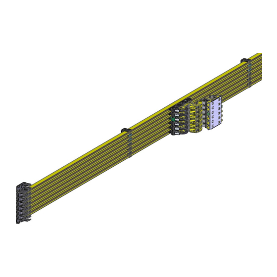
Operating Instructions Single-pole Conductor Rail System SingleFlexLine Program 0815 4 Product Description and Functional Principles 4.1 Brief description Single-pole insulated conductor rails consist of individual conductor rails firmly fixed on a guideway. One or more current collectors fastened to one or more mobile consumers engage with the conductor rails with their current collector heads. The mobile consumers move along the guideway in a linear, track-guided manner. - Page 22 Operating Instructions Single-pole Conductor Rail System SingleFlexLine Program 0815 Fig. 2: System overview *The installation spacing depends on the current collector type (65 mm, 80 mm, 92 mm) Pos. Name End cap Connector Hanger clamp Line feed Expansion unit Transfer caps/ “long” end caps...
- Page 23 Operating Instructions Single-pole Conductor Rail System SingleFlexLine Program 0815 Use of bends in horizontal and vertical curves Insertion direction of the current collector Vertical (from below) Horizontal (from the side) Horizontal bend Inner/outer bend suspension distance: 400 mm suspension distance: 250 mm Horizontal curve bend radius: 1000 mm to ∞...
-
Page 24: Interfaces
Operating Instructions Single-pole Conductor Rail System SingleFlexLine Program 0815 4.2 Interfaces All details are in the catalog, the installation instructions and possibly in the system-specific lay- out. Mechanical interfaces: The current collector must be fastened to the mobile consumer of the machine. The manufacturer/operator of the machine/system ... -
Page 25: Description Of The Components
Operating Instructions Single-pole Conductor Rail System SingleFlexLine Program 0815 4.3 Description of the components Hanger clamp 0815 Hanger clamps for supporting the conductor rail. The hanger clamps listed in the catalog are screwable. In many cases, customer-specific hanger clamps that are inserted in the sup- port profile or are screwed into it are used. - Page 26 Operating Instructions Single-pole Conductor Rail System SingleFlexLine Program 0815 Fixed point cap For mechanical fixing of the conductor rail to the installation structure. Use of mechanical fixing on expanding sections with long systems. 1 = Insertion cam 2 = Fixed point cap...
- Page 27 Operating Instructions Single-pole Conductor Rail System SingleFlexLine Program 0815 End caps/end cap units/line feed These are used as insulating termination of rails and as guides for the sliding contact at a transfer. At a transfer, the current collector is guided from one rail section to the follow- ing section.
- Page 28 Operating Instructions Single-pole Conductor Rail System SingleFlexLine Program 0815 Fig. 14: Expansion module with 20 mm expansion gap Expansion units reduce the system load capacity of the overall system! See Section 3.1 NOTE! Air gap insulation section The air gap insulation sections are used for the electrical isola- tion of the conductor rail.
- Page 29 Operating Instructions Single-pole Conductor Rail System SingleFlexLine Program 0815 Fig. 17: Current collector and current collector unit (for ProEMS type) BAL0815-0002g-US www.conductix.us translated document page 29 of 128...
-
Page 30: Accessories
Operating Instructions Single-pole Conductor Rail System SingleFlexLine Program 0815 4.4 Accessories The following accessory parts are specific, special components and can be additionally ordered from the manufacturer (see manu- facturer catalog): Sliding contact sensor unit A sliding contact sensor unit is available for checking for the pres-... -
Page 31: Transport, Packaging And Storage
Operating Instructions Single-pole Conductor Rail System SingleFlexLine Program 0815 5 Transport, Packaging and Storage 5.1 Safety Required protective equipment: Risk of death due to suspended loads! Falling parts or uncontrolled swinging loads can lead to severe injury or even death. -
Page 32: Transport
Operating Instructions Single-pole Conductor Rail System SingleFlexLine Program 0815 Risk of injury due to cutting and amputation! Cuts and amputations can occur: On packaging material (such as cartons, bands, etc.). DANGER! On sharp edges of the conductor rail. ... -
Page 33: Packaging
Operating Instructions Single-pole Conductor Rail System SingleFlexLine Program 0815 File a complaint on every defect as soon as it is detected. Damage compensation claims may only be made within the applicable claim periods. NOTE! 5.3 Packaging The individually packaged parts have been packed in accordance with the anticipated transport conditions. Only environmentally friendly materials have been used for packaging. -
Page 34: Installation
Operating Instructions Single-pole Conductor Rail System SingleFlexLine Program 0815 6 Installation 6.1 Safety Installation and initial commissioning may only be carried out by specially trained technicians. Required protective equipment: Risk of death due to suspended loads! Falling loads can lead to severe injuries or even death. - Page 35 Operating Instructions Single-pole Conductor Rail System SingleFlexLine Program 0815 Risk of injury due to crushing skin and limbs! There is a risk of crushing of skin and limbs due to: Spring force/gravity (stored energy). DANGER! Current collector (spring force) during installation, disassembly and maintenance.
- Page 36 Operating Instructions Single-pole Conductor Rail System SingleFlexLine Program 0815 Risk of puncture wounds and cuts! The packaging material can contain sharp objects such as nails, struts, steel bands and wood splinters that can cause injury to limbs. CAUTION! → Wear personal protective equipment! →...
-
Page 37: Provide Additional Protection Against Accidental Contact At The Conductor Rail End
Operating Instructions Single-pole Conductor Rail System SingleFlexLine Program 0815 A clearance to the side of the conductor rail of at least 4 mm from metal components must be maintained (see Fig. 20) to prevent mechanical collisions and guarantee suffi- cient electrical insulation distances! NOTE! Fig. -
Page 38: Procedure
Operating Instructions Single-pole Conductor Rail System SingleFlexLine Program 0815 6.3 Procedure 6.3.1 Required tools Standard tools: Measuring tape Calipers Scribe Hexagonal screwdriver (3 mm) Open-end wrench SW7 Screwdriver set Cutting tool (e.g., cordless angle grinder) for producing short lengths ... -
Page 39: Trimming Conductor Rails
Operating Instructions Single-pole Conductor Rail System SingleFlexLine Program 0815 6.3.2.1 Trimming conductor rails The conductor rails have a standard length of 4000 mm. Shorter lengths can be supplied but are generally produced on site. Required tools: Cutting tool, preferably a battery angle grinder with 1 mm cutting disc for the finishing of short lengths. -
Page 40: Making A Notch For The Pe
Operating Instructions Single-pole Conductor Rail System SingleFlexLine Program 0815 6.3.2.2 Making a notch for the PE rail plus Required tools: Notching tool (Order No.: 081094) or side cutter for finishing the ends of the PE rail plus Drill Ø 5 mm ... - Page 41 Operating Instructions Single-pole Conductor Rail System SingleFlexLine Program 0815 → Make a notch with a side cutter: → Slide the conductor bar out of the insulating profile. → Drill the insulating profile (Ø 5 mm) (see Fig. 24). → Cut a 19.5 mm long slot with the side cutter on both sides up to the drill hole (see Fig. 26).
-
Page 42: Making A Bend In The Conductor Rail
Operating Instructions Single-pole Conductor Rail System SingleFlexLine Program 0815 6.3.2.3 Making a bend in the conductor rail Read and observe the additional operating instructions! You can find additional information on the making a bend in a conductor rail in BAL0800-0004. - Page 43 Operating Instructions Single-pole Conductor Rail System SingleFlexLine Program 0815 To avoid undesired deformations of the conductor rail, the plastic insert supplied must be inserted in the slit in the contact surface before forming the bend and the removed once the bending process is complete.
- Page 44 Operating Instructions Single-pole Conductor Rail System SingleFlexLine Program 0815 Required tools: Bending device 081091 Work steps: → Scribe the required bend on a flat surface (e.g., the floor). → When making horizontal bends: Insert the plastic insert in the slot on the conductor rail contact surface with the insulating profile slid open.
-
Page 45: Installing The Conductor Rail System
Operating Instructions Single-pole Conductor Rail System SingleFlexLine Program 0815 6.3.3 Installing the conductor rail system A clearance to the side of the conductor rail of at least 4 mm from metal components must be main- tained (see Fig. 33) to prevent mechanical collisions and guarantee sufficient electrical insulation dis-... -
Page 46: Mounting The Hanger Clamps
Operating Instructions Single-pole Conductor Rail System SingleFlexLine Program 0815 6.3.3.1 Mounting the hanger clamps The following must be observed when mounting the hanger clamps: → Set the hanger clamps at distances of approx. 500 mm and at distances of 400 mm and 250 mm respectively for inner and outer horizontal bends. - Page 47 Operating Instructions Single-pole Conductor Rail System SingleFlexLine Program 0815 Pos. Name Guideway rail Hanger clamp Fig. 36: Comparison of correctly and incorrectly engaged rail Fig. 37: Clip the hanger clamp into the conductor rail Standard hanger clamp for screwing on: To fasten the standard hanger clamps, drill holes must be drilled in the EMS rail.
- Page 48 Operating Instructions Single-pole Conductor Rail System SingleFlexLine Program 0815 Fig. 38: Drilling jig for hanger clamp Fig. 40: Drill hole distance of the female connectors (detail C) Fig. 39: Drill hole distance of the female connectors → Screw the hanger clamp (6) onto the EMS track rail (7) with the cylinder screw and hexagon nut M4 (5) using a 7 mm open-end wrench.
-
Page 49: Mounting The Fixed Point
Operating Instructions Single-pole Conductor Rail System SingleFlexLine Program 0815 Fig. 41: Standard hanger clamps for screwing on code (“click” “scan”), watch animation Mounting Hanger Clamps (clip-in, screwable and turnable). 6.3.3.2 Mounting the fixed point A fixed point consists of a hanger clamp and 2 fixed point clamps per pole. The positions of the fixed points are determined when planning the system. - Page 50 Operating Instructions Single-pole Conductor Rail System SingleFlexLine Program 0815 Fig. 42: Drill the hole for the insertion cam, insulating profile and copper Fig. 43: Rotate the fixed point cap through 180°. element Fig. 44: Insert the insertion cam into the hole BAL0815-0002g-US www.conductix.us...
- Page 51 Operating Instructions Single-pole Conductor Rail System SingleFlexLine Program 0815 Fig. 45: Fully assembled fixed point Pos. Name Insertion cam Fixed point cap Hanger clamp (to screw on) Guideway profile Hanger clamp screw connection with cylin- der screw and hexagon nut M4...
-
Page 52: Mounting Conductor Rail And Connectors (On Straight Routes)
Operating Instructions Single-pole Conductor Rail System SingleFlexLine Program 0815 6.3.3.3 Mounting conductor rail and connectors (on straight routes) The connector (Order No.: 081526-6) may only be used for closed slip ring applications. The mounting of the connector is described in Section 6.3.3.4! NOTE! →... - Page 53 Operating Instructions Single-pole Conductor Rail System SingleFlexLine Program 0815 Fig. 47: Slide the rails onto the connector Fig. 48: Correct position of the clamp Fig. 49: Incorrect position of the clamp Tighten the connector with a 3-mm Hexagonal screw- driver to 2 Nm Fig.
- Page 54 Operating Instructions Single-pole Conductor Rail System SingleFlexLine Program 0815 After mounting the connector cap, check the connection for solidity by gently pulling. If the conductor rails can be pulled apart, the connector clamp is most likely incorrectly mounted (see Fig. 49).
- Page 55 Operating Instructions Single-pole Conductor Rail System SingleFlexLine Program 0815 code (“click” “scan”), watch animation Connecting Rails. During installation, a conductor rail may need to be taken out of a hanger clamp again. There is a disas- sembly tool for this (Order No.: 081092). This is used to disassemble the conductor rail fixed in the hanger clamp and end cap bars (see Fig.
-
Page 56: Mounting Conductor Rail And Connector (In Closed Slip Ring Applications)
Operating Instructions Single-pole Conductor Rail System SingleFlexLine Program 0815 6.3.3.4 Mounting conductor rail and connector (in closed slip ring applications) The connector must not be used in straight routes, but rather only in closed slip ring applica- tions! The mounting of the connector on a straight route is described in Section 6.3.3.2. - Page 57 Operating Instructions Single-pole Conductor Rail System SingleFlexLine Program 0815 → Tap the connector (Pos. 2) into the end of the first conductor rail bend (Pos. 1) with a plastic hammer (see Fig. 59). Fig. 59: Tap the connector (Pos. 2) into conductor rail bend (Pos. 1) →...
- Page 58 Operating Instructions Single-pole Conductor Rail System SingleFlexLine Program 0815 → Slide the connector cap (Pos. 5) over the insulating profile from behind (see Fig. 62) in order to mount the connector cap (Pos. 5) in the insulating profile (see Fig. 62 and Fig. 63). The connector cap (Pos. 5) must completely enclose the insulating profile (see Fig.
- Page 59 Operating Instructions Single-pole Conductor Rail System SingleFlexLine Program 0815 → Mount or connect the further conductor rail bends in the same way in the customer's support structure (substructure) The conductor rail must not be bent further when the connector is mounted! NOTE! →...
- Page 60 Operating Instructions Single-pole Conductor Rail System SingleFlexLine Program 0815 → Slide the last conductor rail bend with the connector into the rail opening of the first conductor rail bend (see Fig. 66). Fig. 66: Connect the last connection point → Slide the connector cap over the connection point from behind and mount it in the insulating profile (see Fig. 62 - Fig. 64).
-
Page 61: Expansion Unit And Expansion Module
Operating Instructions Single-pole Conductor Rail System SingleFlexLine Program 0815 6.3.3.5 Expansion unit and expansion module An expansion unit is a component used to compensate for changes in length of a conductor rail pole and is supplied without conductor rails. It is installed the same as an air gap insulation section (see Section 6.3.3.6). An expansion module consists of expansion units and conductor rails for a specified route length. - Page 62 Operating Instructions Single-pole Conductor Rail System SingleFlexLine Program 0815 The expansion module is available in 2-pole, 3-pole and 4-pole versions. The 2-pole and 3-pole versions have no PE pole, while the 4-pole expansion module is available with a PE/PE pole and without a PE/PE pole (see Table 1).
- Page 63 Operating Instructions Single-pole Conductor Rail System SingleFlexLine Program 0815 Fig. 68: 4-pole and 4-pole expansion modules result in an 8-pole expansion module A rear cable protrudes from the 3-pole expansion module version. This means that a distance of 14 mm from the customer-specific support profile must be...
-
Page 64: Determine The Number Of Expansion Modules
Operating Instructions Single-pole Conductor Rail System SingleFlexLine Program 0815 6.3.3.5.1 Determine the number of expansion modules The number and position of the expansion modules depends on the system layout, the operating temperature range and existing building expansion joints or customer-specific support profiles. - Page 65 Operating Instructions Single-pole Conductor Rail System SingleFlexLine Program 0815 Fig. 69: System layout example Building expansion point Expansion module Fixed point Curves equate to fixed points Switch End cap BAL0815-0002g-US www.conductix.us translated document page 65 of 128...
- Page 66 Operating Instructions Single-pole Conductor Rail System SingleFlexLine Program 0815 Number of Route Route characteristics expansion Note modules - Straight segment Curve radii < 30 m. In case - Length ≤ 100 m of doubt, curves must be - Freely expanding end handled like fixed points - Length >...
- Page 67 Operating Instructions Single-pole Conductor Rail System SingleFlexLine Program 0815 Number of Route Route characteristics expansion Note modules - Short segment - Length: < 8 m When determining the num- ber of expansion modules, it must be taken into account that the expansion gap of the...
-
Page 68: Mounting The Expansion Module With A Setting Aid
Operating Instructions Single-pole Conductor Rail System SingleFlexLine Program 0815 6.3.3.5.2 Mounting the expansion module with a setting aid Requirements: The conductor rail system is fully mounted up to the position of the expansion module. The distance from the system edge to the last hanger clamp must be 125 mm. Move a hanger clamp if necessary (see Fig. 70). - Page 69 Operating Instructions Single-pole Conductor Rail System SingleFlexLine Program 0815 Fig. 72: Setting aid (Pos. 1) is incorrectly mounted Fig. 73: Setting aid (Pos. 1) is correctly mounted Required tools: Optional: Setting aid for setting the expansion gap (Order No.: 08-S902-0002P)
- Page 70 Operating Instructions Single-pole Conductor Rail System SingleFlexLine Program 0815 Work steps: → Push the clamping unit of the connector (Pos. 3) completely into the conductor bar of each conductor rail pole (see Fig. 74). Ensure that the clamping unit is fully seated in the conductor bar. The clamping unit must not slip over the insulating profile (see Fig.
- Page 71 Operating Instructions Single-pole Conductor Rail System SingleFlexLine Program 0815 → Slide the connector cap (Pos. 4) over the clamping unit (see Fig. 79). Ensure that the connector cap (Pos. 4) only fits over the clamping unit from one side, e.g., the higher side (Pos. A) of the connector cap (Pos. 4) must point in the direction in which the expansion module is to be mounted (see Fig.
- Page 72 Operating Instructions Single-pole Conductor Rail System SingleFlexLine Program 0815 → Hang the expansion module (Pos. 2) in the hanger clamps (see Fig. 82). Fig. 82: Hang the expansion module in the hanger clamps → Carefully tap the expansion module into the clamping unit of the connector (see Fig. 83) with light taps (tool: plastic hammer) and tighten the socket head screw (Pos.
- Page 73 Operating Instructions Single-pole Conductor Rail System SingleFlexLine Program 0815 The insulating profile of the expansion module (Pos. 2) has a recess at each conductor rail pole end (see Fig. 85) so that the clamping unit (Pos. 3) does not slide out of the con- ductor bar and over the insulating profile (Pos.
- Page 74 Operating Instructions Single-pole Conductor Rail System SingleFlexLine Program 0815 → Slide the connector cap (Pos. 4) over the clamping unit (see Fig. 87). Ensure that the connector cap (Pos. 4) only fits over the clamping unit from one side, e.g., the higher side (Pos. A) of the connector cap (Pos. 4) must point in the direction in which the expansion module is to be mounted (see Fig.
- Page 75 Operating Instructions Single-pole Conductor Rail System SingleFlexLine Program 0815 → Do not remove the setting aids from the expansion module until the following fixed point (see also BAL0815-0002) has been mounted. Check whether the dimension of every expansion gap is 20 mm (see Fig. 90).
-
Page 76: Mounting The Expansion Module Without A Setting Aid
Operating Instructions Single-pole Conductor Rail System SingleFlexLine Program 0815 6.3.3.5.3 Mounting the expansion module without a setting aid If no setting aids (Order No.: 08-S902-0002P) are available, the individual expansion gaps in the expansion unit or in the expansion module per conductor rail pole must be set according to the mounting temperature following the mounting and can be read from the following diagram (see Fig. - Page 77 Operating Instructions Single-pole Conductor Rail System SingleFlexLine Program 0815 The setting dimension measures from plastic cap to plastic cap (Pos. 2) e.g., the setting dimension always includes the plastic bar (Pos. 1) (see Fig. 92). 10 mm 20 mm Fig. 92: Setting dimension including bar width (Pos. 1) BAL0815-0002g-US www.conductix.us...
-
Page 78: Mounting Air Gap Insulation Section
Operating Instructions Single-pole Conductor Rail System SingleFlexLine Program 0815 6.3.3.6 Mounting air gap insulation section Air gap insulation sections are used for electrical separation, e.g., for electrical segmentation or block separation. These are used on all or single poles depending on the required function. - Page 79 Operating Instructions Single-pole Conductor Rail System SingleFlexLine Program 0815 → Mark the 46 mm dimension on the conductor rail at the desired point (see project-specific documents) and cut it out with a cutting tool (see Section 6.3.2.1) (see Fig. 94).
- Page 80 Operating Instructions Single-pole Conductor Rail System SingleFlexLine Program 0815 → Slide the line feed clamp with the crimped connection cable into both conductor rail ends (see Fig. 97). Fig. 97: Slide the line feed clamp into the conductor rail ends →...
- Page 81 Operating Instructions Single-pole Conductor Rail System SingleFlexLine Program 0815 Fig. 99: End cap (Pos. 4) encloses the insulating profile (Pos. 5) Fig. 100: Tighten cylinder screws (Pos. 6) After mounting the end cap, check the connection for solidity by gently pulling.
- Page 82 Operating Instructions Single-pole Conductor Rail System SingleFlexLine Program 0815 Fig. 101: Line feed clamp correctly mounted Fig. 102: Line feed clamp incorrectly mounted → Clip the connecting bar (Pos. 7) over the mounted end caps (see Fig. 103). Fig. 103: Mount connecting bar (Pos. 7) BAL0815-0002g-US www.conductix.us...
- Page 83 Operating Instructions Single-pole Conductor Rail System SingleFlexLine Program 0815 → Re-mount the conductor rail with the installed air gap insulation section in the hanger clamp. The distance from the rear edge of the end cap to the hanger clamp is 30 mm (see Fig. 104). Ensure that the air gap insulation section is in contact with the support structure and not with a recess (see Fig.
-
Page 84: Mounting A Section Line Feed
Operating Instructions Single-pole Conductor Rail System SingleFlexLine Program 0815 6.3.3.7 Mounting a section line feed → The section line feed is installed instead of a connector. Here, a different clamping part and a line feed cap with room for a connecting cable to run out of it are used. - Page 85 Operating Instructions Single-pole Conductor Rail System SingleFlexLine Program 0815 After installing the end cap, check the connection for solidity by gently pulling. If the conductor rails can be pulled apart, the connector clamping unit is likely mounted incorrectly (see Fig. 107).
-
Page 86: Mounting End Caps And End Line Feeds
Operating Instructions Single-pole Conductor Rail System SingleFlexLine Program 0815 6.3.3.8 Mounting end caps and end line feeds To allow the mounting of the end caps, a clearance of 110 mm from the beginning of the guideway (see profile must be maintained at the full height! Fig. - Page 87 Operating Instructions Single-pole Conductor Rail System SingleFlexLine Program 0815 Fig. 118: Incorrect position of the clamping unit Fig. 117: Correct position of the clamping unit For end line feeds, the power can be supplied at the end of the route. An end line feed consists of an end cap with a line feed clamping unit.
- Page 88 Operating Instructions Single-pole Conductor Rail System SingleFlexLine Program 0815 It is recommended that the conductor rail is not yet engaged in the adjacent hanger clamp! NOTE! Fig. 120: Clip the conductor rail into place → Engage the end cap/end line feed into the retaining plate (see Fig. 120).
-
Page 89: Mounting The Current Collector
NOTE! not be sharply kinked. Conductix-Wampfler recommends using the PE current collectors in assembly types 081506…, 081507…, 081508…, 081509…without cams, and the assembly types equipped with interchanging pro- tection 081506…, 081507…, 081508…, 081509…with cams. Special towing plates with a slot at the PE position are also provided for the assembly. - Page 90 Operating Instructions Single-pole Conductor Rail System SingleFlexLine Program 0815 The location of the PE slot position (see A in Fig. 123) on the towing plate can be read from the order number: For example: 081055-14X08X006X000 In this example the last digit of the second to last block of digits is ≠ 0, but rather a “6”. This means that the location of the PE slot is in the 6th position: Fig.
- Page 91 Operating Instructions Single-pole Conductor Rail System SingleFlexLine Program 0815 Tolerances in the X-axis and Y-axis: ± 15 mm 1 = Integrated cable 2 = Hexagon screw M5 DIN EN 4017 (DIN 933)* Number of Poles Fig. 126: EMS current collector (08150A / B…) *The screw is not part of the scope of delivery.
- Page 92 The current collector is mounted onto the towing plate: Fig. 127: Mount the PH current collector (Order No.: 081506…, 081507…, 081508…, 081509…) onto towing plate Conductix-Wampfler recommends using the PE current collectors in assembly types 081506…, 081507…, 081508…, 081509…without cams, and the assembly types equipped with interchanging pro- tection 081506…, 081507…, 081508…, 081509…with cams.
- Page 93 → For types without an integrated cable guide, take care with the selection of the connecting cable and ensure the connecting cables are installed without tensile or directional forces: → Use only highly flexible Conductix-Wampfler cables! Basically, only use connecting cables with copper conductors. → Use a blade receptable with protective cap for the flexible connecting cables.
- Page 94 Operating Instructions Single-pole Conductor Rail System SingleFlexLine Program 0815 Risk of wear and damage! The distance from the securing base surface of the current collector to the running surface of the con- ductor rail is an important functional dimension. This dimension changes in curves if the current col- WARNING! lector is not installed directly under the wheel contact point of the EMS hanger.
- Page 95 Operating Instructions Single-pole Conductor Rail System SingleFlexLine Program 0815 Bending up of the socket sleeve! If the socket sleeve is placed incorrectly on the collector brush, the socket sleeve bends up, the socket sleeve is damaged and the contact with the brush is minimized.
-
Page 96: Additional Documents
Operating Instructions Single-pole Conductor Rail System SingleFlexLine Program 0815 6.4 Additional documents Read and respect the additional operating instructions! You can find further information on the installation of conductor rail systems in the following instructions: MV0815-0006 Transfers BAL0815-0001 Sliding contact sensor unit ... -
Page 97: Commissioning
Operating Instructions Single-pole Conductor Rail System SingleFlexLine Program 0815 7 Commissioning 7.1 Safety Personnel: The conductor rail system must only be commissioned and operated for the first time after a repair by qualified electricians! The qualified electricians must meet the requirements described in Section 2.2.1. - Page 98 Operating Instructions Single-pole Conductor Rail System SingleFlexLine Program 0815 Risk of injury due to crushing skin and limbs! There is a risk of crushing of skin and limbs due to: Spring force/gravity (stored energy). DANGER! Current collectors (spring force) during preassembly, installation, operation, maintenance and dis- ...
- Page 99 Operating Instructions Single-pole Conductor Rail System SingleFlexLine Program 0815 Risk of injury due to sensitizing material and dust! Dust from the sliding contacts collects in the conductor rails and the guide profile. This dust is very fine and is categorized as a health risk. Working regularly with the conductor rail system and/or not DANGER! applying the requisite level of care when handling accumulated dust (e.g., cleaning the system with...
-
Page 100: Testing And Initial Commissioning
Operating Instructions Single-pole Conductor Rail System SingleFlexLine Program 0815 7.2 Testing and initial commissioning 7.2.1 Inspection list Risk of death due to electrical shock! WARNING! Check Checked Installation height as per specifications (see Section 3) All installed components are clean, dry and undamaged. -
Page 101: Initial Commissioning Of The Conductor Rail System
Operating Instructions Single-pole Conductor Rail System SingleFlexLine Program 0815 7.2.2 Initial commissioning of the conductor rail system Each time before the machine/system is started, measure the insulation resistance of the conductor rail system according to locally applicable technical standards, directives and legal regulations. -
Page 102: Operation
Operating Instructions Single-pole Conductor Rail System SingleFlexLine Program 0815 8 Operation The only operations required to operate the conductor rail system are switching the power supply on and off to stop/activate the system, see Section 8.2. The safety information in Section 8.1 must be observed to guarantee safety during operation. - Page 103 Operating Instructions Single-pole Conductor Rail System SingleFlexLine Program 0815 Risk of injury due to falling conductor rails! The mountings of the conductor rail can fail and the conductor rail can fall down. Components can be damaged if the following or similar materials are stored in the vicinity of the conductor rail:...
-
Page 104: Normal Operation
Operating Instructions Single-pole Conductor Rail System SingleFlexLine Program 0815 Fire hazard due to overload or sparking! Fire hazards occur due to overloaded cables, electrical arcs, short circuits or sparking. Sparking can occur with poorly serviced, contaminated conductor rails or if the installation does not comply with the DANGER! required tolerances. -
Page 105: Stopping The System
Operating Instructions Single-pole Conductor Rail System SingleFlexLine Program 0815 8.3 Stopping the system Requirement: Risk of injury due to electric shock! → Disconnect the conductor rail system from the power supply according to the 5 Safety Rules and secure it against being switched back on. For the 5 Safety Rules, see Section 2.5. -
Page 106: Maintenance And Service
Operating Instructions Single-pole Conductor Rail System SingleFlexLine Program 0815 9 Maintenance and Service 9.1 Safety The system must only be serviced and maintained by specialist personnel! Requirement: Disconnect the system from power and secure against being switched on again. Required protective equipment:... - Page 107 Operating Instructions Single-pole Conductor Rail System SingleFlexLine Program 0815 Risk of injury due to materials and substances! Respiratory complaints and eye irritation may occur due to airborne dust. There is a health hazard due to airborne respirable dust. One result may be cancer.
- Page 108 Operating Instructions Single-pole Conductor Rail System SingleFlexLine Program 0815 Risk of injury due to crushing skin and limbs! Skin and limbs can be crushed: When packing components and handling long loads DANGER! If transport crates are dropped With incorrect suspension points for transport crates ...
- Page 109 Operating Instructions Single-pole Conductor Rail System SingleFlexLine Program 0815 Risk of injury due to hot components! Components can get hot during operation. → Operation is only permitted in areas inaccessible to the public and out of manual reach. WARNING! → The danger zone must be enclosed by the customer or protection ensured by distance.
-
Page 110: Tools And Materials
Operating Instructions Single-pole Conductor Rail System SingleFlexLine Program 0815 Performing maintenance work on current collectors Risk of injury due to crushing skin and limbs! There is a risk of crushing of skin and limbs due to: Spring force/gravity (stored energy). -
Page 111: Maintenance Plan
Operating Instructions Single-pole Conductor Rail System SingleFlexLine Program 0815 9.3 Maintenance plan The following tasks fall under the category “Servicing”: SERVICING Inspection Maintenance Repair Checks Cleaning Repair Measurements Washing Replacing Testing Resetting Readjusting The following sections describe the maintenance tasks required for optimal and trouble-free operation. The tasks specified and performed as per the maintenance plan must be logged. - Page 112 Operating Instructions Single-pole Conductor Rail System SingleFlexLine Program 0815 Required protective equipment: Danger of sensitization, irritation of the mucous membranes and respiratory diseases due to dust! Dust from the sliding contacts collects in the conductor rails and the guide profile. This dust is very DANGER! fine and is categorized as a health risk.
- Page 113 Operating Instructions Single-pole Conductor Rail System SingleFlexLine Program 0815 The following table covers the most usual test steps. You can find details for cleaning and maintenance in WV0800-0001 and WV0800-0002. The cleaning distance is individual and depends on the degree of contamination and the intensity of the use of the system.
- Page 114 Operating Instructions Single-pole Conductor Rail System SingleFlexLine Program 0815 To be per- Interval Servicing task formed by Check the sliding contact insulation for cracks and abrasion. → replace the current collector if the sliding contact insulation is damaged or cracked.
-
Page 115: Troubleshooting
→ Only allow troubleshooting to be conducted by personnel from or authorized by the manu- facturer. The faults that, to Conductix-Wampfler's best knowledge, tend to arise are listed in the following table (see Section 10.1) together with their corresponding remedial measures. - Page 116 Operating Instructions Single-pole Conductor Rail System SingleFlexLine Program 0815 Only operate the conductor rail system in areas inaccessible to the public! Operation is only permitted in areas inaccessible to the public and out of manual reach. → The danger zone must be enclosed by the customer or protection ensured by distance!
- Page 117 Operating Instructions Single-pole Conductor Rail System SingleFlexLine Program 0815 Risk of injury due to cutting and amputation! Cuts and amputations can occur on: Sharp edges of the general components DANGER! Sharp edges of the conductor rails Cut edges when trimming the conductor rails ...
- Page 118 Operating Instructions Single-pole Conductor Rail System SingleFlexLine Program 0815 Before working on these components! → Disconnect the conductor rail system from the power supply according to the 5 Safety Rules and secure it against being switched back on. For the 5 Safety Rules, see Section 2.5.
-
Page 119: Fault Correction Table
Operating Instructions Single-pole Conductor Rail System SingleFlexLine Program 0815 10.1 Fault correction table Fault Cause Corrective measures The sliding contacts are un- The current collector heads' range of movement is restricted. Only use original Conductix- evenly worn. Wampfler current collector heads,... - Page 120 Operating Instructions Single-pole Conductor Rail System SingleFlexLine Program 0815 Fault Cause Corrective measures cable, replace if necessary. Check the installation position at various points in the system. Collision with system components Check the system's layout, fasten the affected components in such a...
-
Page 121: Disassembly And Disposal
Operating Instructions Single-pole Conductor Rail System SingleFlexLine Program 0815 11 Disassembly and Disposal 11.1 Safety Personnel: Must only be conducted by trained technicians. At least 2 people Requirement: Disconnect the system from power and secure against being switched on again. - Page 122 Operating Instructions Single-pole Conductor Rail System SingleFlexLine Program 0815 Risk of injury due to cutting and amputation! Cuts and amputations can occur on: Sharp edges of the conductor rails. DANGER! Cut edges when trimming rails. → Wear personal protective equipment! →...
- Page 123 Operating Instructions Single-pole Conductor Rail System SingleFlexLine Program 0815 Risk of injury due to dust! Dust due to abrasion (sliding contacts, copper rails, plastic) can cause respiratory com- plaints, choking and eye irritation. DANGER! → Clean the system before starting work.
-
Page 124: Disassembly
Operating Instructions Single-pole Conductor Rail System SingleFlexLine Program 0815 11.2 Disassembly After the system is no longer in use, the device must be disassembled and environmentally friendly disposal carried out. Before starting disassembly: Risk of injury due to impacts and punctures/stabs from conductor rails sliding out! -
Page 125: Disposal
Operating Instructions Single-pole Conductor Rail System SingleFlexLine Program 0815 Risk of injury when removing the connector! The connector is very large compared to the insulation profile and the conductor bar and e.g., a saw blade could easily become trapped in it. The saw could also jump and injure the installer. -
Page 126: Further Documents
Operating Instructions Single-pole Conductor Rail System SingleFlexLine Program 0815 12 Further Documents 12.1 Applicable documents Seq. no. Document number Document name WV0800-0001 Cleaning conductor rails WV0800-0002 Conductor rail maintenance plan MV0815-0006 Transfers MV0815-0008 Code band profile for product range 0815... -
Page 127: Index
Operating Instructions Single-pole Conductor Rail System SingleFlexLine Program 0815 13 Index Accessories ................ 30 Material defects ..............6 Accidents ................17 Operation ................. 102 Additional documents ............96 Operator ................12 Commissioning ..............97 Packaging ................33 Copyright ................6 Personnel ................ - Page 128 Operating Instructions Single-pole Conductor Rail System SingleFlexLine Program 0815 USA / Latin America Canada México Brazil 10102 F Street 1435 Norjohn Court Calle Treviño 983-C Rua Luiz Pionti, 110 Omaha, NE 68 127 Unit 5 Zona Centro Vila Progresso Burlington, ON L7L 0E6 Apodaca, NL México 66600...
Need help?
Do you have a question about the SingleFlexLine Program 0815 and is the answer not in the manual?
Questions and answers