
Related Manuals for Conductix-Wampfler Safe-Lec 2


Summary of Contents for Conductix-Wampfler Safe-Lec 2
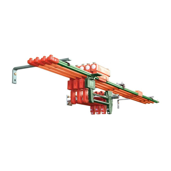
- Page 1 Safe-Lec 2 “V” Contact Bar Installation, Operation & Maintenance Manual XA-964200.17 - 03.15.24 SAFE-LEC 2 CONDUCTOR BAR MANUAL...
- Page 2 Buyer’s name - provided that Seller shall have the right to elect to defend any such suit or action for the account of Buyer. The foregoing shall be the exclusive remedies of the Buyer and all persons and entitles claiming through the Buyer. SAFE-LEC 2 CONDUCTOR BAR MANUAL...
- Page 3 Ask us for a quote on expert system installations,inspections, preventative maintenance, and repairs/retrofits. As the world’s largest single source manufacturer of mobile electrification products, Conductix-Wampfler has the unique ability to offer a degree of service not found anywhere else. Conductix-Wampfler’s team of highly qualified service technicians and engineers have years of experience servicing our complete line of products.
-
Page 4: Table Of Contents
8.0 Tools Needed 8.1 Bolted Steel/Copper Joint Installation SECTION 9 - BOLTED ALUMINUM JOINT ASSEMBLY 9.0 Tools Needed 9.1 Bolted Aluminum Joint Installation SECTION 10 - JOINT COVER ASSEMBLY 10.0 Install Joint Cover onto Bolted Assemblies SAFE-LEC 2 CONDUCTOR BAR MANUAL... - Page 5 20.1 Transfer Cap Installation 20.2 Transfer Cap Mounting Details SECTION 21 - ASSEMBLY OF ISOLATION SPLICE ASSEMBLIES 21.0 Tools Needed 21.1 Installation SECTION 22 - SYSTEM MAINTENANCE AND INSTALLATION NOTES 22.0 Maintenance Notes 22.1 Installation Notes SAFE-LEC 2 CONDUCTOR BAR MANUAL...
- Page 6 24.2 Collector Spacing for Installations with Pickup Guides 24.3 Hanger Clamp Spacing for Installations with Pickup Guide 23.4 Assembly for 1,2,3 & 4-way Pickup Guide SECTION 25 - HANGER CENTERS DIAGRAM SECTION 26 - CONDUCTOR BAR DE-RATING CHART CONTACT INFORMATION SAFE-LEC 2 CONDUCTOR BAR MANUAL...
-
Page 7: Section 1 - Safety
1.2.3 The obligations agreed upon in the delivery agreement and our General Terms and Conditions of business apply, as do the delivery conditions of the manufacturer and the legal regulations applicable at the time the contract was concluded. 1.2.4 All products are subject to technical modifications in the context of improvement of function and further development. SAFE-LEC 2 CONDUCTOR BAR MANUAL... -
Page 8: Personnel Requirements-Qualifications
Unauthorized persons who do not meet the requirements described here are not acquainted with the dangers in the working area. Keep unauthorized personnel away from the working area. In case of doubt, address the person and direct them away from the working area. Stop working, as long as unauthorized persons are in the working area. SAFE-LEC 2 CONDUCTOR BAR MANUAL... -
Page 9: Personnel Requirements-Training
Breathing mask (FFP-3 - according to country-specific requirements): For protection against materials, particles, and organisms. In this case, for protection against the dust produced by the abrasion of carbon brushes and the PVC insulation of the conductor rail. SAFE-LEC 2 CONDUCTOR BAR MANUAL... -
Page 10: Section 2 - Product Disposal
All other components are to be disposed of in accordance with their material composition. Take care with items identified as Substances of Concern. 2.0.3 Local authorities or special disposal companies can provide information about environmentally appropriate disposal. SAFE-LEC 2 CONDUCTOR BAR MANUAL... -
Page 11: Section 3 - Overview
230’ (70M) Max. Steel Bars Conductor Bar For curves and lateral entry, 160’ (49M) Max. Copper Bars Section 14’-9” (4.5M) 44.3 (1.125M) NOTE: Maximum length without expansions is 492’ (150M), use anchor clamp at center Figure: 3-2 SAFE-LEC 2 CONDUCTOR BAR MANUAL... -
Page 12: Environmental Considerations
Hydrochloric Acid Hydrofluoric Acid • • Sodium Hydrochloride • Ammonium Chloride Chlorine Bleach • • Chloride Ions • Fluoride Ions WARNING • Do not use standard (black) or medium heat (red) hangers in the above environment SAFE-LEC 2 CONDUCTOR BAR MANUAL... -
Page 13: Installation Tools
Open/box end wrenches (use ratcheting box-end wrenches if you have them) > 8mm > 10mm > 13mm • Hacksaw • Flat file and/or rat tail file to remove burrs on field cut conductors • Pliers • #1 Phillips Head Screwdriver SAFE-LEC 2 CONDUCTOR BAR MANUAL... -
Page 14: Section 4 - General Assembly Instructions
1. Ensure the power is locked out-tagged out. 2. Install the hangers per instructions (See Table of Contents). 3. Roll adjacent conductors in the hangers as shown in Section 6.2. Conductix-Wampfler recommends the first accessible conductor being the ground conductor. -
Page 15: Phase 5 - Collector Positioning
Keep accessories at least 6” from hanger brackets. • Follow all torque specifications. • Allow for movement of accessories due to expansion. Connect only flexible power cables to powerfeed assemblies. • • Keep collectors straight, level, and aligned with conductors. SAFE-LEC 2 CONDUCTOR BAR MANUAL... -
Page 16: Section 5 - Support Brackets
> Maximum allowable deviation from datum height + 5.0 mm (+3/16”). 5.1 Advantage of Factory Made Brackets 5.1.1 Safe-Lec 2 Hanger Brackets come complete with all necessary mounting holes for easy installation of hangers via slide in slots or holes. -
Page 17: Section 6 - Conductor Hangers
2. Assemble as shown in the diagram, ensuring the correct alignment is observed. (See Figure 6-1). 3. Finger tighten M8 nut. 4. Snap conductor bars into hangers. 5. Tighten M8 nut to Conductix-Wampfler recommended torque of 8 Nm (5-6 ft-lbs.) NOTE: •... -
Page 18: Installing Conductors Into Hanger
SECTION 6 - CONDUCTOR HANGERS 6.3 Installing Conductors Into Hanger “SNAP” INSTALLED Recommended Location for Step 1 Step 2 Ground Rail Figure: 6-2 SAFE-LEC 2 CONDUCTOR BAR MANUAL... -
Page 19: Section 7 - Anchor Hanger Support Assembly
4. Tighten M8 Bolt to a torque of 8 Nm (5-6 ft. lbs). M8 Lock Washer M8 Screw M8 Nut M8 Flat Washer M5 Screw M5 Flat Washer M5 Nut Clamp Anchor Half Figure: 7-1 SAFE-LEC 2 CONDUCTOR BAR MANUAL... -
Page 20: Section 8 - Bolted Steel/Copper Joint Assembly
6. Check that both faces of the conductor bar are touching each other and there is no gap exceeding 0.5mm (0.02”) at the faces. NOTE: • If the conductor was field cut, file off all burrs on conductor ends before assembling splices. Washer Joint Bolt Alignment Mark Joint Plate Conductor Bar Figure: 8-1 SAFE-LEC 2 CONDUCTOR BAR MANUAL... -
Page 21: Section 9 - Bolted Aluminum Joint Assembly
If the conductor was field cut, file off all burrs on conductor ends before assembling splices. Exposed length of bar should be 33mm (1.3”) per end. Washer Joint Plate Bolt Conductor Bar Conductor Bar Apply Electrical Joint Compound part no: XA-15629 to mating surfaces 33 mm (1.3”) Figure: 9-1 SAFE-LEC 2 CONDUCTOR BAR MANUAL... -
Page 22: Section 10 - Joint Cover Assembly
2. Fit the joint cover over the bolted joint. Joint cover MUST NOT be opened up more than 45° on either side during the assembly over the joint. Ensure the “Location Section” sits between the two bolts. 3. Close the flaps in the direction “B”. Ensure the flaps “click” home on both sides. Figure: 10-1 SAFE-LEC 2 CONDUCTOR BAR MANUAL... -
Page 23: Section 11 - End Cap Onto Conductor Bar Assembly
End Cap Top Lock Washer Square Bolt Flush with Joint Plate Top bar end Joint Plate Bottom End Cap End Plug (11.9) Conductor Bar & Cover 1.10-1.70 for Reference Only (27.9-43.2) End Cap Bottom Figure: 11-1 SAFE-LEC 2 CONDUCTOR BAR MANUAL... -
Page 24: Aluminum/Stainless Steel Conductor Bar Installation
7. Align Bottom Cover with Top Cover and End Plug. Apply slow but firm pressure to both Top and Bottom Covers, until all four tabs have snapped securely into place. End Cap Top Lock Washer Flat Washer Square Bolt End Cap (11.9) Condcutor Bar & Cover End Plug 1.10-1.70 for Reference Only (27.9-43.2) End Cap Bottom Figure: 11-2 SAFE-LEC 2 CONDUCTOR BAR MANUAL... -
Page 25: Section 12 - Expansion Section Assembly
1446 985 1159 238 1092 802 1292 906 1051 200 1009 759 1181 848 1097 805 1031 771 Table: 12-0 NOTE: • For systems longer than those in the table above, use: (L-492)/X=number of expansion units. SAFE-LEC 2 CONDUCTOR BAR MANUAL... -
Page 26: Expansion Section Installation
(1.77) (1.69) (1.57) (1.50) (1.38) (1.30) (1.18) (1.10) (0.98) (0.91) (0.79) (0.71) (0.59) (0.51) -25° (-13) (1.97) (1.89) (1.77) (1.69) (1.57) (1.50) (1.42) (1.30) (1.22) (1.14) (1.02) (0.94) (0.83) (0.75) (0.67) (0.55) (0.47) Table: 12-1 SAFE-LEC 2 CONDUCTOR BAR MANUAL... -
Page 27: Section 13 - End Powerfeed Assembly
Maximum cable size is 25 sq mm PVC 600/1000V stranded copper conductor (#4 AWG Extra Flexible) Lock Washer Powerfeed End Cap Half Nut Clamp End Bolt These faces Joint Plate to be flush Figure: 13-1 SAFE-LEC 2 CONDUCTOR BAR MANUAL... -
Page 28: Section 14 - Low Amp Joint Powerfeed Assembly
7. Once in position close flaps and ensure flaps click home. NOTE: • Joint must not support cable. • Max. cable size 10sq. mm pvc 600/1000V stranded copper conductor (#8 AWG Extra Flexible). Powerfeed Cap Lock Washer Figure: 14-1 SAFE-LEC 2 CONDUCTOR BAR MANUAL... -
Page 29: Installation Up To And Including 250 Amps
“X” Powerfeed Cover “X” Powerfeed Case Clip Assembly Bolt Washer Grommet Washer Legs clip under support ears on Powerfeed Joint Cover conductor cover. Conductor Cover Support Ears Powerfeed Top Hat Assembly Splice Bolt Figure: 14-2 SAFE-LEC 2 CONDUCTOR BAR MANUAL... -
Page 30: Section 15 - Powerfeed And Cover Assembly
Powerfeed Case Clip Assembly Bolt Grommet Lock Washer Legs to clip under support ears Washer on conductor cover Powerfeed Shunt Link Screw Powerfeed Joint Cover Conductor Cover Support Ears Powerfeed Top Hat Assembly Splice Bolt Figure: 15-1 SAFE-LEC 2 CONDUCTOR BAR MANUAL... -
Page 31: Section 16 - Terminal Guidelines Chart
1.59 5/16 XA-310601 J972 1.94 5/16 1/OAN-2/0 XA-310401 L973 2.25 1.04 3/OAN-4/0 XA-310701 M972 2.28 1.12 5/16 4/OAN - 250 kcmil XA-310912B XA-310501 54178 2.33 1.25 5/16 300 kcmil XA-310911 XA-310101 1.13 XA-310034B XA-310101 1.13 SAFE-LEC 2 CONDUCTOR BAR MANUAL... -
Page 32: Section 17 - 100 Amp Collector Mounting Details
18" for 100 (31.8) Amp Collectors and 19.5" 200 Amp Collectors to ensure proper head movement on the collectors. Figure: 17-1 Working Range 2.75 (69.9) Contact Surface 1.25 (31.8) 4.0 (102.0) Figure: 17-2 SAFE-LEC 2 CONDUCTOR BAR MANUAL... -
Page 33: Section 18 - 200 Amp Collector Mounting Details
4. Insert the two M3 x 30 screws through the collector head and into the flag and flag nuts. 5. Tighten the M3 screws on 0.9 Nm (8 in.-lb). Figure: 18-3 SAFE-LEC 2 CONDUCTOR BAR MANUAL... -
Page 34: Section 19 - Customer Supplied Cable Installation
Page 31. 6. We highly recommended the use of flexible, finely stranded cables to wire collectors. The use of cables with solid conductors is not recommended. Cable Entry Hole Figure: 19-1 SAFE-LEC 2 CONDUCTOR BAR MANUAL... -
Page 35: Section 20 - Transfer Cap Assembly
5. Fit nut and washers in order shown. 6. Tighten nut to a recommended torque of 28.4 Nm (20-21 ft.-lbs). Lock Washer Flat Washer Support Stud Transfer Cap 22mm (0.87”) 33mm (1.3”) 43mm (1.69”) Figure: 20-1 SAFE-LEC 2 CONDUCTOR BAR MANUAL... -
Page 36: Transfer Cap Mounting Details
10 mm (0.4”) 5 mm (0.19”) Figure: 20-2 20.2.2 Plan view of transfer caps showing maximum alignment tolerance. 2mm (.08”) Figure: 20-3 NOTE: • Where transfer caps are used in a system, tandem collectors must be used. SAFE-LEC 2 CONDUCTOR BAR MANUAL... -
Page 37: Section 21 - Assembly Of Isolation Splice Assemblies
3. Place cap over bolt. 4. Fit washers and nuts in the order shown. 5. Tighten nuts to a recommended value of 8 Nm (5-6 ft-lbs). Washer Bolt Conductor Bar Joint Plate Conductor Bar Figure: 21-1 SAFE-LEC 2 CONDUCTOR BAR MANUAL... -
Page 38: Section 22 - System Maintenance And Installation Notes
7. Ensure all armored cables are terminated into a suitable junction box and only flexible cables are installed into the powerfeed assemblies. 8. Ensure conductor bars DO NOT support the weight of the feed cables. 9. Conductix-Wampfler recommends that the first accessible conductor bar should be the ground bar. SAFE-LEC 2 CONDUCTOR BAR MANUAL... -
Page 39: Section 23 - Collector Contact Shoe And Shoe Holder
3. Replace shoe with new shoe. Place shim in pocket between setscrew and shoe, and install new shoe into collector head. See Figure: 23-2. 4. Tighten set screw to 1.69 Nm (15 in.-lb). Shoe Wear Line Figure: 23-0 Shoe Shoe Shim Shim Shim Pocket Shim Pocket Figure: 23-1 Figure: 23-2 SAFE-LEC 2 CONDUCTOR BAR MANUAL... -
Page 40: Section 24 - Pickup Guides
24.0.2 Installation tolerances must be taken into consideration. Simultaneous alignment gaps with maximum tolerances in the X and Y directions are not permitted. 10.28 (261) 5/16-18 4.23 (107) 6.62 (168) 1.30 1.30 1.30 (33) (33) (33) Figure: 24-1 6.62 (168) 14.17 (360) 17.05 (433) Figure: 24-2 SAFE-LEC 2 CONDUCTOR BAR MANUAL... -
Page 41: Dimensions
DANGER The user must ensure that the current collector between the pickup guides are disconnected from power or are protected against accidental contact! SAFE-LEC 2 CONDUCTOR BAR MANUAL... -
Page 42: Hanger Clamp Spacing For Installations With Pickup Guide
The middle distance (phase distance) between two conductors is 43 mm. This is reduced to 33 mm at the pickup guide in order to ensure that the collectors enter the pickup guide precisely. 24.3 Hanger Clamp Spacing For Installations With Pickup Guide 39.37 59.06 MAX TYP (1000) (1500 MAX) Figure: 24-5 1.30 1.69 (33) (43) Figure: 24-6 SAFE-LEC 2 CONDUCTOR BAR MANUAL... -
Page 43: Assembly For 1,2,3 & 4-Way Pickup Guide
Lock Washer Supplied Flat Washer Brackets * Bolt 78.0 mm Supoort Stud (3.07”) Lock Washer Flat Washer Figure: 24-7 NOTE: When using pickup guides, collector part XA-SL2C-100SX-1M-PG must be used. Please contact the factory when ordering. SAFE-LEC 2 CONDUCTOR BAR MANUAL... -
Page 44: Section 25 - Hanger Centers Diagram
XA-310918 XA-310824 XA-310834 XA-310829 43mm MIN (1.69”) 43mm MIN 43mm MIN (1.69”) (1.69”) XA-310882 XA-310861 XA-310899 XA-310871 43 mm 43mm (1.69”) (1.69”) XA-310821 43 mm (1.69”) XA-310857 XA-310835 XA-310859 43 mm (1.69”) 43 mm (1.69”) SAFE-LEC 2 CONDUCTOR BAR MANUAL... -
Page 45: Section 26 - Conductor Bar De-Rating Chart
SECTION 26 - CONDUCTOR BAR DE-RATING CHART SAFE-LEC 2 CONDUCTOR BAR MANUAL... - Page 46 (+52 81) 1090 9025 (+52 81) 1090 9013 Phone +1-402-339-9300 Phone +1-450-565-9900 +1-402-339-9627 +1-450-951-8591 (+52 81) 1090 9014 Fax (+55 11) 4813 7330 info.us@conductix.com info.ca@conductix.com info.mx@conductix.com info.br@conductix.com latinamerica@conductix.com Contact us for our Global Sales Offices SAFE-LEC 2 CONDUCTOR BAR MANUAL XA-964200.17 - 03.15.24...
Need help?
Do you have a question about the Safe-Lec 2 and is the answer not in the manual?
Questions and answers