Sign In
Upload
Download
Add to my manuals
Delete from my manuals
Share
URL of this page:
HTML Link:
Bookmark this page
Add
Manual will be automatically added to "My Manuals"
Print this page
×
Bookmark added
×
Added to my manuals
Manuals
Brands
Intel Manuals
Server
R2000WT
System integration and serive manual
Intel R2000WT Series System Integration And Serive Manual
Hide thumbs
Also See for R2000WT Series
:
Configuration manual
(104 pages)
1
2
3
4
5
6
7
8
9
10
11
12
13
14
15
16
17
18
19
20
21
22
23
24
25
26
27
28
29
30
31
32
33
34
35
36
37
38
39
40
41
42
43
44
45
46
47
48
49
50
51
52
53
54
55
56
57
58
59
60
61
62
63
64
65
66
67
68
69
70
71
72
73
74
75
76
77
78
79
80
81
82
83
84
85
86
87
88
89
90
91
92
93
94
95
96
97
98
99
100
101
102
103
104
105
106
107
108
109
110
111
112
113
114
115
116
117
118
119
120
121
122
123
124
125
126
127
128
129
130
131
132
133
134
135
136
137
138
139
140
page
of
140
Go
/
140
Bookmarks
Advertisement
Quick Links
Download this manual
®
Intel
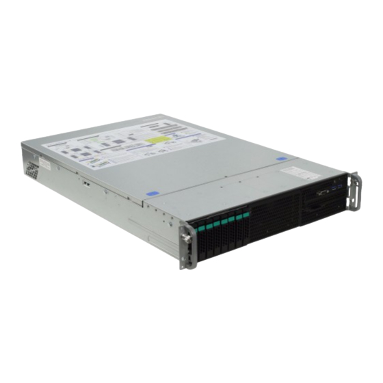
Server System R2000WT Product Family
System Integration and Service Guide
A Guide for Technically Qualified Assemblers of Intel identified Subassemblies/Products
Rev 1.6
September 2017
Intel
®
Server Boards and Systems
Previous
Page
Next
Page
1
2
3
4
5
Advertisement
Need help?
Do you have a question about the R2000WT Series and is the answer not in the manual?
Ask a question
Questions and answers
Related Manuals for Intel R2000WT Series
Server Board Intel R2000WT Configuration Manual
(104 pages)
Server Intel R2000SC Series Service Manual
Server system (71 pages)
Server Intel R2000SC Series Quick Installation User's Manual
Server system r2000sc famil (20 pages)
Server Intel R2000LH2 Service Manual
Server system (86 pages)
Server Intel R2000LH2 Quick Installation User's Manual
Server system (20 pages)
Server Intel R200LH2 Service Manual
Servier system (83 pages)
Server Intel R2000LT2 Technical Product Specification
Product family server system r2000lh2/t2 (126 pages)
Server Intel R2000GZ series Installation Manual
(22 pages)
Server Intel R2000GL Service Manual
(83 pages)
Server Intel R2000WF Configuration Manual
(104 pages)
Server Intel R2000WF series Service Manual
(140 pages)
Server Intel R2000WF Technical Product Specification
Product family (167 pages)
Server Intel R2000WF Configuration Manual
Server board/chassis/system (127 pages)
Server Intel R1000WF Series Configuration Manual
Server board/chassis/server system (142 pages)
Server Intel R2000BB series Quick Installation User's Manual
(22 pages)
Server Intel R2000BB Series Service Manual
(88 pages)
This manual is also suitable for:
R2312wt series
R2208wt series
R2216wt series
R2224wt series
R2308wt series
Print
Rename the bookmark
Delete bookmark?
Delete from my manuals?
Login
Sign In
OR
Sign in with Facebook
Sign in with Google
Upload manual
Upload from disk
Upload from URL


Need help?
Do you have a question about the R2000WT Series and is the answer not in the manual?
Questions and answers