
Related Manuals for HySecurity StrongArm 14F


Summary of Contents for HySecurity StrongArm 14F
- Page 1 Programming and Operations Manual StrongArm ™ 14F, 20, 28, 36, DOT 28 Vehicular barrier gate operator with Smart Touch Controller...
- Page 2 (This page intentionally blank) StrongArm Programming and Operations hysecurity.com | 800-321-9947 MX3657-01 Rev. D ©2020...
-
Page 3: Table Of Contents
StrongArmDOT 28 Break-Away Arm Installation ......................42 Valve Adjustments ................................44 Adjust Pressure Relief Valve ............................44 Adjusting Brake Valve ..............................44 Limit Switch Adjustments ...............................45 Emergency Override ..............................46 Manual Bypass Valve ..............................46 Cycle Test the Arm ..............................46 Emergency Fast Close ..............................47 MX3657-01 Rev. D ©2020 hysecurity.com | 800-321-9947... - Page 4 Installing a Push Button Device for Emergency Fast Operate (EFO) ................47 ..................49 ntrApment roteCtIon Table 4: HySecurity Gate Operators maintaining Object Detection ................50 Supply Power to the Sensors ............................51 External Entrapment Protection .............................52 PHOTO EYE FUNCTION: ...............................53 ..................55 ontrol...
- Page 5 Smart Touch Analyze and Retrieve Tool (S.T.A.R.T.) .....................115 What You Need .................................115 Installing S.T.A.R.T. Software .............................115 Software Maintenance ..............................116 Electrical Controls ................................116 Clock Battery Replacement ............................116 Mechnical Controls...............................117 Stopping the Gate ..............................117 Starting the Gate ..............................117 Mechanical Maintenance .............................117 MX3657-01 Rev. D ©2020 hysecurity.com | 800-321-9947...
- Page 6 Smart Touch: WireLess Edge Gate Link & Photo Eye ....................130 StrongArm Installer Checklist ............................131 ......................131 ArrAnty ......................132 peCIfICAtIons NOTICE Visit https://hysecurity.com/technical-support/ for installation manuals, replacement part instructions, part dia- grams and more. StrongArm Programming and Operations hysecurity.com | 800-321-9947 MX3657-01 Rev. D ©2020...
-
Page 7: S Trong A Rm I Nstallation O Verview
16 ft (4.9 m) Inside Obstruction Loop Barrier Arm StrongArm Front panel Base plate: Create a template StrongArm chassis to mount four anchor bolts on the concrete pad. MX3657-01 Rev. D ©2020 hysecurity.com | 800-321-9947... -
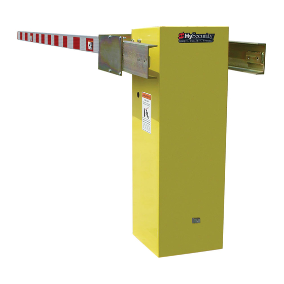
Page 8: Strongarm Components
Switch, Disconnect Limit Cam Keypad Switch, Hold Open Cylinder Switch, Disconnect Pin, Cylinder Eyebolt, Nut and NordLock, Cylinder Anchor Motor, Electric Hose Kit Pump Pack Chassis Front panel not shown StrongArm Programming and Operations hysecurity.com | 800-321-9947 MX3657-01 Rev. D ©2020... -
Page 9: Strongarm Pump Pack Components
Replace with Breather Cap Valve Check, Endhead Valve Coil, Directional Braking Kit Valve, Braking Valve, 2 Position Directional Valve, Manual Bypass Flow Control Reservoir Valve, Check, Back-to-Back Quick Disconnect, Socket Valve, Manual Bypass MX3657-01 Rev. D ©2020 hysecurity.com | 800-321-9947... - Page 10 (This page intentionally blank) StrongArm Programming and Operations hysecurity.com | 800-321-9947 MX3657-01 Rev. D ©2020...
-
Page 11: Important Safety Instructions
Indicates a hazardous situation which, if not avoided, COULD similar equipment. COULD result in DEATH or SERIOUS INJURY. result in DEATH or SERIOUS INJURY. Proof of attending a HySecurity Technical Training CAUTION CAUTION seminar within the past three years. Indicates a hazardous situation which, if not avoided, Indicates a hazardous situation which, if not avoided, COULD Signifi... -
Page 12: Important Safety Information
Class IV personnel or via closed circuitry. StrongArm Programming and Operations hysecurity.com | 800-321-9947 MX3657-01 Rev. D ©2020... - Page 13 A minimum of two (2) WARNING SIGNS shall be installed, in the area of the gate. Each placard is to be visible by persons located on the side of the gate on which the placard is installed. HySecurity provides two warning signs already applied to barrier arms and two signs for attachment to both sides of the operator chassis.
- Page 14 Locate photo sensors accordingly. Be certain that a suffi cient number of sensors are used so that pedestrians are protected from entrapment in arm travel and all hazard areas are fully protected. Most HySecurity gate operators require external entrapment sensors that utilize Normally Closed (NC) contact means of monitoring. HySecurity gate operators utilizing the SmartCNX Controller require external entrapment sensors that have a 10k Ohm or 4-wire pulsed monitoring scheme.
- Page 15 IMPORTANT SAFETY INFORMATION HySecurity Vertical Barrier Arm Safety and Traffi c Control ARM INSTALLATION Do not install the operator where arm moves within 16 inches of a rigid object or within 10 feet of high power wires when the barrier arm is raised.
- Page 16 IMPORTANT SAFETY INFORMATION HySecurity Vertical Barrier Arm Safety and Traffi c Control High levels of force are generated by moving traffi c barrier arms. Ensure arm installation, warning signs and safety devices are properly installed and operated to address the following hazards: •...
- Page 17 IMPORTANT SAFETY INFORMATION HySecurity Vertical Barrier Arm Safety and Traffi c Control Traffi c Light Separate Pedestrian Non-Contact Loop Walkway Sensor Beam (Optional) Sensor Photo Secure Side Gate Barrier Operator Bollards LED Lights Speed Pedestrian Bump Warning & (4 Each) Hazard Stripes Traffi...
- Page 18 HySecurity Vertical Barrier Arm Safety and Traffi c Control The following photo eye sensors have been shown in testing to provide the best performance when installed with HySecurity operators. HySecurity supports installers who install recommended sensors. “Compatible Sensors” are still certifi ed to meet UL 325 6th edition installation with HySecurity operators.
- Page 19 BATTERY SAFETY disposal of any electrical components, waste or oil associated with this equipment. HySecurity operators use sealed Absorbed Glass Mat (AGM) When the life cycle of this equipment is over, remove battery batteries and HySecurity highly recommends replacing used ...
- Page 20 Wind load is not as much of a factor when considering using a barrier gate for a particular site instead of a slide or swing gate. However, when installing a barrier arm gate in a high wind area, Hysecurity suggests the following: •...
-
Page 21: Proper Grounding And Breather Cap Installation
2. Replace the vent plug with the breather cap. StrongArm Remove Vent Plug Replace with Breather Cap Grade level Cut-away view Consult local codes for proper depth Concrete pad Ground rod Important Safety Instructions MX3657-01 Rev. D ©2020 hysecurity.com | 800-321-9947... -
Page 22: Manual Release: Manual Bypass Valve
6. Twist the black Manual Bypass knob so it re-seats itself in the closed position. Other types of release mechanisms exist. For example, the Fire and Emergency Access Lock Box is available through HySecurity distributors. Contact your distributor for more information. StrongArm Programming and Operations hysecurity.com | 800-321-9947... -
Page 23: Installation
Keep in mind that a space of 7 X 11” just inside of the operator door is where the conduits must enter into the operator. HySecurity recommends a slab reaches below the local frost line. See the footprint plan and elevation view. - Page 24 1. Be sure to install all of the warning signs or labels that were supplied with this operator. If these labels have been misplaced or lost, call your local distributor or the factory for replacements. StrongArm Programming and Operations hysecurity.com | 800-321-9947 MX3657-01 Rev. D ©2020...
- Page 25 Installation MX3657-01 Rev. D ©2020 hysecurity.com | 800-321-9947...
- Page 26 46 ¾ StrongArm Programming and Operations hysecurity.com | 800-321-9947 MX3657-01 Rev. D ©2020...
- Page 27 Installation MX3657-01 Rev. D ©2020 hysecurity.com | 800-321-9947...
- Page 28 (This page intentionally blank) StrongArm Programming and Operations hysecurity.com | 800-321-9947 MX3657-01 Rev. D ©2020...
-
Page 29: Power
Code (NEC) - Article 250 requires a separate earth ground in addition to the required equipment ground. HySecurity recommends grounding the operator with a separate earth ground rod (or a similar device in the case of crash products) to shield the operator against electromagnetism and other electrical signals that may cause, erratic operation with, or damage to, the Smart Touch Controller and other electrical parts. -
Page 30: Site Considerations
Site Considerations HySecurity gate operators are intended for permanent installation. Make sure you prepare the site with the following considerations: • Make sure all electrical wiring is properly routed via conduits. • Check the distance of the wiring run from the main panel to the gate operator. Make sure the wire size of the branch circuit supplying power to the gate operator is large enough to avoid excess voltage drop. -
Page 31: Turning The Power Switch On
HySecurity information, refer to Smart Touch Controller Inputs on page 78. SPARE INPUT MX000585 VERSION EMERG CLOSE FIRE DEPT OPEN Smart Touch Controller LIMIT DUAL GATE RADIO OPTIONS OPEN +24V +24V EDGE Power MX3657-01 Rev. D ©2020 hysecurity.com | 800-321-9947... -
Page 32: Wire Sizing And Runs
20 ga 3.5 miles (5.6 km) 22 ga 2.7 miles (4.3 km) 24 ga 2.0 miles (3.2 km) 26 ga 1.0 mile (1.6 km) 28 ga 3700 feet (1.1 km) StrongArm Programming and Operations hysecurity.com | 800-321-9947 MX3657-01 Rev. D ©2020... -
Page 33: Strongarm Wiring Charts (Incoming Power)
975 (297m) 515 (157m) 475 (145m) 260 (79m) 2220 (670m) 1915 (584m) 1550 (472m) 815 (248m) 750 (229m) 410 (125m) 3550 (1082m) 3080 (939m) 2465 (751m) 1305 (398m) 1200 (366m) 650 (198m) Power MX3657-01 Rev. D ©2020 hysecurity.com | 800-321-9947... - Page 34 2840 (866m) 2750 (838m) 1150 (350m) 11700 (3566m) 9350 (2850m) 7400 (2255m) 4550 (1387m) 4400 (1341m) 1800 (549m) 18500 (5639m) 14800 (4511m) 11700 (3566m) 7200 (2194m) 7000 (2134m) 2900 (884m) StrongArm Programming and Operations hysecurity.com | 800-321-9947 MX3657-01 Rev. D ©2020...
-
Page 35: Control Transformer Connections (Non-Ups)
You need a 2-inch (5 cm) diameter conduit for hydraulic hoses and a ¾-inch (19 mm) conduit for electrical wiring. AC input power is connected to the hydraulic pump and electrical components enclosure (HydraSupply). A supplemental manual, provided with the product, describes the installation overview, wiring and conduit considerations. Power MX3657-01 Rev. D ©2020 hysecurity.com | 800-321-9947... -
Page 36: Dc Power Supply (Ups) Connections
When the local AC power fails, the UPS back up system continues to move the gate. System features are covered in the HyInverterAC Installation and Reference Manual shipped with the product and available online at www.hysecurity.com. NOTICE: The AC Power Supply with HyInverter AC option is intended for single phase (1 hp) gate operators and single phase (2 hp) gate operators that use Variable Speed Drives (VFD). -
Page 37: Initial Setup
If you are unsure of the usage classification, refer to Identifying Gate Operator Category and Usage Class on page 5. It explains the different usage site classifications for UL 325. Initial Setup MX3657-01 Rev. D ©2020 hysecurity.com | 800-321-9947... -
Page 38: Replace The Red Vent Plug With The Breather Cap
Manual Bypass Quick Disconnects knob • Premature battery drain on DC operators Brake valves are factory-set to midpoint, two turns. This should be sufficient for most applications. StrongArm Programming and Operations hysecurity.com | 800-321-9947 MX3657-01 Rev. D ©2020... -
Page 39: Leveling And Balancing Arm
4. The only remedy for an arm that is too heavy is to reduce the length of the arm, or add additional counterweight which is described in the next section. Initial Setup MX3657-01 Rev. D ©2020 hysecurity.com | 800-321-9947... -
Page 40: Strongarm Counterweights Installation
Stud Length (inches) (feet) per side (inches) side 2.5” 2.5” 2.5” 2.5” 2.5” 2.5” 2.5” 2.5” 2.5” 2.5” 2.5” 2.5” 3.5” 3.5” 3.5” 5.0” 5.0” 6.0” 6.0” 7.5” 7.5” 7.5” StrongArm Programming and Operations hysecurity.com | 800-321-9947 MX3657-01 Rev. D ©2020... - Page 41 BARRIER ARM FLAT WASHER SHEAR BRASS BOLT LOCATIONS NYLON LOCKNUT BREAKAWAY SLEEVE ARM KING PIN CAST FLAT ADAPTER WASHER SERVICE BOLT BRASS SHEAR BOLTS LOCK WASHERS HEX NUT StrongArm CounterWeight Installation Initial Setup MX3657-01 Rev. D ©2020 hysecurity.com | 800-321-9947...
-
Page 42: Strongarmdot 28 Break-Away Arm Installation
8. Using a socket and ratchet, secure the gate saver sleeve arm to cast adapter, and gate saver barrier arm to gate saver sleeve arm using six bolts, flat washers, and nylon locknuts. See “E” in drawing on next page. StrongArm Programming and Operations hysecurity.com | 800-321-9947 MX3657-01 Rev. D ©2020... - Page 43 WASHERS CAST HEX NUT ADAPTER SERVICE Figure 1. StrongArmDOT 28 Breakaway Arm Installation Instructions StrongArm Break-Away Arm CounterWeight Installation | www.hysecurity.com STRONGARMDOT 28 BREAKAWAY ARM ADDENDUM MX4436 REV. B © 2018 Initial Setup MX3657-01 Rev. D ©2020 hysecurity.com | 800-321-9947...
-
Page 44: Valve Adjustments
As the arm lowers and trips the limit switch, it should smootly drift to StrongArm Programming and Operations hysecurity.com | 800-321-9947 MX3657-01 Rev. D ©2020... -
Page 45: Limit Switch Adjustments
2. Press Open. Position the arm so it stops within 10° Limit switches of vertical. • To raise arm, adjust Open Limit Cam outward. • To lower the arm, adjust Open Limit Cam inward. Initial Setup MX3657-01 Rev. D ©2020 hysecurity.com | 800-321-9947... -
Page 46: Emergency Override
Cycle Test the Arm 1. Tighten all lock nuts on the adjustor valves. 2. Cycle the arm Open and Close a few times. If adjustments are needed, follow the steps above. StrongArm Programming and Operations hysecurity.com | 800-321-9947 MX3657-01 Rev. D ©2020... -
Page 47: Emergency Fast Close
SENSOR 3 DO NOT USE CHARGER AC LOSS HySecurity Power Supply Board LOCK INTERLOCK MX000585 VERSION EMERG CLOSE FIRE DEPT OPEN Smart Touch Controller LIMIT DUAL GATE RADIO OPTIONS OPEN +24V +24V Initial Setup MX3657-01 Rev. D ©2020 hysecurity.com | 800-321-9947... - Page 48 (This page intentionally blank) StrongArm Programming and Operations hysecurity.com | 800-321-9947 MX3657-01 Rev. D ©2020...
-
Page 49: Entrapment Protection
Install non-contact sensors (photo eyes) beneath the barrier arm to help prevent the barrier arm from lowering on a person if standing under the raised arm. HySecurity gates monitor normally closed (NC) sensors. Wire your NC sensors to SENSOR input terminals (SENSOR 1, SENSOR 2, or SENSOR 3) on the Smart Touch Controllers. -
Page 50: Table 4: Hysecurity Gate Operators Maintaining Object Detection
Table 4: HySecurity Gate Operators maintaining Object Detection Table 4 indicates those HySecurity gate operators that may be within the exception parameters of UL 325 or comply with standards other than UL 325, but continue to maintain object detection capabilities. HySecurity strongly recommends that you assess every site for entrapment zones and provide the necessary protection to guard against entrapment. -
Page 51: Supply Power To The Sensors
All external entrapment protection sensors must be wired to the SENSOR COM terminal for monitoring purposes. Review sensor wiring diagrams found in Wiring HySecurity Sensors: Smart Touch on page 121. Until the gate operator receives a command to run (open or close command), the sensors are not receiving power. -
Page 52: External Entrapment Protection
Some manufacturers label an output as NO, when it is actually an NC contact. If the photo eye has a solid-state output you must choose a sinking type connection. StrongArm Programming and Operations hysecurity.com | 800-321-9947 MX3657-01 Rev. D ©2020... -
Page 53: Photo Eye Function
Photo eyes usually provide alignment aid LEDs for this setup, but they can be hard to see. HySecurity provides a unique feature that turns power on to photo eyes and causes buzzer to chirp when the photo eyes enter and exit alignment. - Page 54 (This page intentionally blank) StrongArm Programming and Operations hysecurity.com | 800-321-9947 MX3657-01 Rev. D ©2020...
-
Page 55: Control Panel Overview
Provides inputs for peripherals and accessories, 2 electromechanical user relays (250VAC, 10A), one solid state user relay (30VDC, 3A). For Power ON/OFF more information, refer to STC Terminal Inputs on page 78. Switch Control Panel Overview MX3657-01 Rev. D ©2020 hysecurity.com | 800-321-9947... -
Page 56: Strongarm Wiring Diagram
EMERG CLOSE Not Shown FIRE DEPT OPEN Smart Touch Controller LIMIT DUAL GATE RADIO OPTIONS MX002440 OPEN +24V +24V EDGE HySecurity Class 2 Control Circuit* Limit Switches Directional Valve StrongArm Programming and Operations hysecurity.com | 800-321-9947 MX3657-01 Rev. D ©2020... -
Page 57: Stc Board, Power Supply Board And Display
PHOTO EYE SENSOR 3 LOCK INTERLOCK MX000585 CLOSE DIRECTION VERSION EMERG CLOSE FIRE DEPT OPEN Smart Touch Controller LIMIT DUAL GATE RADIO OPTIONS OPEN +24V +24V Smart Touch Controller Ribbon cable Control Panel Overview MX3657-01 Rev. D ©2020 hysecurity.com | 800-321-9947... - Page 58 (This page intentionally blank) StrongArm Programming and Operations hysecurity.com | 800-321-9947 MX3657-01 Rev. D ©2020...
-
Page 59: Display & Menu Options
NOTE: Use a laptop computer at your place of business to conveniently download the free START software and most current software version from www.hysecurity.com before heading out into the field. This makes it easy to adjust settings using a laptop. -
Page 60: Menu Mode And The Stc Keypad
Press Next or Previous. Press Select. Continue pressing Next to view Blinking characters Advance - press Next Two left characters blink. all selections. become static. Previous - press Previous StrongArm Programming and Operations hysecurity.com | 800-321-9947 MX3657-01 Rev. D ©2020... -
Page 61: Run Mode And The Stc Keypad
The type of information that may scroll across the display includes: interlocked or sequenced gate (if applicable), operator type (OT), gate handing, Usage Class (UC), buss voltage, and life cycle counter. OT 1 OPERATOR UC 2 SLIDEDRIVER USAGE CLASS Example of Operator Status Displays Display & Menu Options MX3657-01 Rev. D ©2020 hysecurity.com | 800-321-9947... -
Page 62: Stop The Status Display Scrolling
To conserve energy, the display dims after a period of time if no keypress, run command or fault occurs. When an event (keypress, run command, or error/alert/fault notification) occurs, the display returns to full brightness. StrongArm Programming and Operations hysecurity.com | 800-321-9947 MX3657-01 Rev. D ©2020... -
Page 63: Check The Software Version
Refer to the chart, Smart Touch Controller: Menu Mode Navigation Buttons on page 60. Table 5 describes the User Menu items and supplies the factory defaults. (Factory default settings shown in bold.) Display & Menu Options MX3657-01 Rev. D ©2020 hysecurity.com | 800-321-9947... -
Page 64: User Menu: Table 5
Set to 3: Available on barrier operators only and UC 4 if sensor inputs set to 1 “NOT USED”. Buzzer beeps when gate starts to move and continues throughout gate travel. StrongArm Programming and Operations hysecurity.com | 800-321-9947 MX3657-01 Rev. D ©2020... - Page 65 PC laptop loaded 1 to record all operator open and close events, in with HySecurity free addition to the normal alert, fault and error logs. This S.T.A.R.T. software is parameter automatically resets to the default 0 (off) required.
-
Page 66: Installer Menu
NOTE: Installer Menu options can also be configured through the use of a laptop computer and S.T.A.R.T. software. See Smart Touch Analyze and Retrieve Tool information found on the HySecurity website: www.hysecurity.com Table 6 describes the Installer Menu items and supplies the factory defaults. (Factory settings shown in bold.) - Page 67 (Security Gate) NOTE: After selecting SG settings, consider A to A accessing the User Menu in each gate B to B operator to address the Close Timer (CT) setting. Display & Menu Options MX3657-01 Rev. D ©2020 hysecurity.com | 800-321-9947...
- Page 68 7 to 99 seconds PARTIAL OPEN an adjustable distance by setting the open duration. The available time settings are 7 to 99 seconds. The default setting [PO 0] leaves this input inactive. StrongArm Programming and Operations hysecurity.com | 800-321-9947 MX3657-01 Rev. D ©2020...
- Page 69 Same as Sensor 1 SENSOR 2 SENSOR #2 TYPE +24V SENSOR COM S3 0 Same as Sensor 1 Same as Sensor 1 SENSOR 3 SENSOR #3 TYPE +24V SENSOR COM Display & Menu Options MX3657-01 Rev. D ©2020 hysecurity.com | 800-321-9947...
- Page 70 NOTE: The shaded Installer Menu items do not appear when Build Year is set to 2 (BY 2). Exceptions exist for barrier arms, CRASH products, operators set to pre-2016 and Usage Class IV provisions. StrongArm Programming and Operations hysecurity.com | 800-321-9947 MX3657-01 Rev. D ©2020...
- Page 71 4 = 105s time. With updated software versions, TL 5 = 135s appears in the Installer Menu even without the User Relay option 8 being utilized. Display & Menu Options MX3657-01 Rev. D ©2020 hysecurity.com | 800-321-9947...
- Page 72 RLD0 RUN MODE Controls the HY-5B Shadow/Reset Loop HY-5B RESET LOOP SET 1 = Show frequency detector. (Shadow Loop Set) 2 = Show call level 0-7 3 = Set Frequency StrongArm Programming and Operations hysecurity.com | 800-321-9947 MX3657-01 Rev. D ©2020...
-
Page 73: Setting The Close Timer
Refer to Menu Mode Navigation on page 60. 3. To exit the User Menu, press the Menu button. The gate status appears in the display indicating you have returned to Run Mode. Display & Menu Options MX3657-01 Rev. D ©2020 hysecurity.com | 800-321-9947... -
Page 74: Test The Operator
NOTE: If additional accessories are to be added, read about STC Inputs & Wiring on page 75. Access control device Warning signs Outside Photo eye Obstruction Loop Reset Loop Inside Obstruction Loop StrongArm Programming and Operations hysecurity.com | 800-321-9947 MX3657-01 Rev. D ©2020... -
Page 75: Stc Inputs & Wiring
Make Connections on the Smart Touch Controller • Integrate with Security Systems • Adapt User Relays for your Gate Site LED lights when energized Hy5B Refer to the HySecurity website for more information about Hy5B installation and use. Hy5A Hy5B Power Connector RS-485... -
Page 76: Overview Of The Stc And Power Supply Board
3 terminals. Any combination of the 5 Smart Touch Controller available terminals can be used to draw LIMIT DUAL GATE RADIO OPTIONS the 3A maximum. OPEN +24V +24V Smart Touch Controller Tact button StrongArm Programming and Operations hysecurity.com | 800-321-9947 MX3657-01 Rev. D ©2020... -
Page 77: Integrating With Security Systems And Hynet™ Gateway
The RS-485 interface is also used to communicate with the HyNet Gateway, a web-enabled interface. To view the user guide and quick start information regarding HyNet Gateway SFP 4/1, go to the HySecurity website, Technical_Support_Installation_Manuals. -
Page 78: Smart Touch Controller Inputs
(multi-function) Open Partial Open Partial NOTE: NOT USED on Monitored access StrongArm. Terminal is only controls used in slide gates. Adjustable through the Installer Menu from 7 to 99. StrongArm Programming and Operations hysecurity.com | 800-321-9947 MX3657-01 Rev. D ©2020... -
Page 79: Connecting Accessory Devices
VEHICLE DETECTOR - 24 Volts Protection Sensors on page gate operator receives a SHADOW/RESET VEHICLE DETECTOR Common 37 and Wiring HySecurity run command. SENSOR 1 Sensors: Smart Touch on page Use these terminals to 121. preserve battery power. SENSOR... - Page 80 Smart Touch Controller RADIO OPTIONS LIMIT DUAL GATE OPEN +24V +24V NOTE: See Wiring HySecurity Sensors: Smart Touch on page 121, for photo eye and gate edge connections. LOOP Not to Scale StrongArm Programming and Operations hysecurity.com | 800-321-9947 MX3657-01 Rev. D ©2020...
-
Page 81: User Relays - Programming Procedure
7/10ths of a second before the operator starts moving the gate and remains active while moving. Output remains active, for a few seconds, after stopping. STC Inputs & Wiring MX3657-01 Rev. D ©2020 hysecurity.com | 800-321-9947... - Page 82 Relay 1, 2 or 3 power is very low, but the output ceases when the battery is dead. The relay is triggered when the battery is less than 20 volts. StrongArm Programming and Operations hysecurity.com | 800-321-9947 MX3657-01 Rev. D ©2020...
- Page 83 Inbound Transient/Lot Output N.O. Input. The relay outputs a 250ms pulse used to R1 and R2, R4 increment the transient and total vehicle counts. Refer through R11 to the HySecurity Parking supplement for more detailed TRANSIENT information. USER Outbound Transient/Lot Output N.O.
-
Page 84: Hy8Relay Module Option
IALD, then CLD, are tripped and released. This SPECIAL USER activity signals a customer has exited the facility. Set aside for Factory Use HySecurity Testing Only Do not use Test Open Pulse Output pulses five seconds after close limit is activated. -
Page 85: Bi-Parting & Dual Gate Systems
NOTE: Both StrongArm gate systems need to have compatible software versions installed on their Smart Touch Controllers. Dual StrongArms Bi-Parting & Dual Gate Systems MX3657-01 Rev. D ©2020 hysecurity.com | 800-321-9947... -
Page 86: Dual Gate Wiring Connections
Smart Touch Controller LIMIT DUAL GATE RADIO OPTIONS LIMIT DUAL GATE RADIO OPTIONS OPEN +24V +24V OPEN +24V +24V Wire Diagram: Interlocked Pair of Operators wired to DUAL GATE Inputs StrongArm Programming and Operations hysecurity.com | 800-321-9947 MX3657-01 Rev. D ©2020... -
Page 87: Dual Or Sequenced Gates: Power, Software & Accessory Requirements
RESET button. • For up-to-date features, keep the most current software loaded on both gate operators. Software downloads are available at www.hysecurity.com. Make it part of your maintenance routine to check for and install software updates on a regular basis. •... -
Page 88: Connecting Sequenced Gates
Use a 2-pair, twisted, shielded cable with one pair of wires used to connect A-A and B-B terminals between the two boards. The other pair will connect the Common terminals. The shield should then be grounded on one end to one of the operators. StrongArm Programming and Operations hysecurity.com | 800-321-9947 MX3657-01 Rev. D ©2020... - Page 89 SG 4 = Sequenced Gate #4 configuration (only used with HydraSupply XL) NOTE : Set gate operators on the site to the uniquely paired number. Refer to the site designs on the following pages. Bi-Parting & Dual Gate Systems MX3657-01 Rev. D ©2020 hysecurity.com | 800-321-9947...
-
Page 90: Sequenced Gate: Configuration #1
C/L gate 1 to 5 ft (31 to 152 cm). Center to center between gates: Dimension “F” = 10 to 15 ft (3 to 3.6 m) 4 ft minimum (122 cm) 9 ft maximum (274 cm) StrongArm Programming and Operations hysecurity.com | 800-321-9947 MX3657-01 Rev. D ©2020... -
Page 91: Sequenced Gate: Configuration #2
(or the Security Gate is manually closed). **NOTICE Center to center between gates: 4 ft minimum (122 cm) 9 ft maximum (274 cm) Drawings not to scale. Bi-Parting & Dual Gate Systems MX3657-01 Rev. D ©2020 hysecurity.com | 800-321-9947... - Page 92 Page intentionally left blank StrongArm Programming and Operations hysecurity.com | 800-321-9947 MX3657-01 Rev. D ©2020...
-
Page 93: Ehicle D Etector I Nstallation
Vehicle Detector Installation HySecurity recommends that vehicle detectors be used for free exit and obstruction sensing logic only. The exception is in parking or barrier arm applications where detectors may also be used to close the gate. In applications employing our swing, vertical lift, or sliding gate operators, closing logic cannot be used except when the anti-tailgate logic is employed. -
Page 94: Vehicle Detector Installation: Hy5A And Hy5B
The Smart Touch Controller provides an interface for up to four different vehicle detector functions. NOTE: Standard box type 11 pin (24 VDC or 24 VAC) vehicle detectors may be connected in the traditional manner, but HySecurity Hy5A mini-detector modules plug directly into the Smart Touch Controller, making field installation much faster and enhancing performance. -
Page 95: Connecting Hy5A Vehicle Detectors
NOTE: If there is any detector fault, the gate operator functions as if the detector is triggered. Pressing the RESET button: • Clears any errors • Tunes the detectors on connected loops • Un-installs any detectors that have been removed Vehicle Detector Installation MX3657-01 Rev. D ©2020 hysecurity.com | 800-321-9947... -
Page 96: View Call Level In Real Time
If the test outcome is good and all the loops are operating properly, you may need to adjust the Hy5A sensitivity dial, so the call level reads in the 5 to 6 range. StrongArm Programming and Operations hysecurity.com | 800-321-9947 MX3657-01 Rev. D ©2020... -
Page 97: Installing Standard 11-Pin Box Type Vehicle Detectors
LOCK INTERLOCK VEHICLE LOOP MX000585 VERSION EMERG CLOSE FIRE DEPT OPEN Common Smart Touch Controller To LOOP terminal on Smart Touch Controller LIMIT DUAL GATE RADIO OPTIONS OPEN +24V +24V Vehicle Detector Installation MX3657-01 Rev. D ©2020 hysecurity.com | 800-321-9947... -
Page 98: Strongarm Htg Loop Layout
StrongArm Programming and Operations hysecurity.com | 800-321-9947 MX3657-01 Rev. D ©2020... -
Page 99: Photo Eye Installation
NOTE: To enable fully automatic operation, this gate operator requires a MINIMUM of one external entrapment protection sensor to monitor potential entrapment zones in either the open or close direction of travel. Visit www.hysecurity.com/gatesafety for more information on UL 325 standards and gate safety. -
Page 100: Photo Eyes (Non-Contact) Installation
Compatibility The UL 325 standard requires that a photoelectric sensor be laboratory tested and “recognized” under UL 325. In order to be compatible with all HySecurity operators, a photo eye must be rated to function from 24 VDC source power. -
Page 101: Configuration
HySecurity Sensors: Smart Touch on page 121. NOTE: HySecurity gate operators, manufactured with 2016 (or later) in the serial number, require Normally Closed output sensors. Some manufacturers label an output as N.O. (normally open), when it is actually an N.C. (normally closed) contact. Review External Entrapment Protection Sensors monitored by HySecurity Gate Operators on page iii. -
Page 102: Retro-Reflective Photo Eye Systems
Realign the eye for the position of the reflector. NOTE: If the photo eye is realigned, be sure to perform the centering test again to verify that the reflector is truly in the center. StrongArm Programming and Operations hysecurity.com | 800-321-9947 MX3657-01 Rev. D ©2020... -
Page 103: Using Photo Eye Sensors Instead Of Vehicle Loops
UL 325 Standard of Safety for “monitored” external entrapment protection. To understand external SENSOR 1 entrapment protection and how HySecurity equipment monitors sensors, refer to the section titled Entrapment Photo Eye sensor terminal connections when PE sensors used in place of vehicle loops Protection. -
Page 104: Photo Eye Alignment Feature
Press Next or Previous. Press Select. Continue pressing Next to view Blinking characters Advance - press Next Two left characters blink. all selections. become static. Previous - press Previous StrongArm Programming and Operations hysecurity.com | 800-321-9947 MX3657-01 Rev. D ©2020... -
Page 105: Troubleshooting
These diagnostic messages can be retrieved for analysis purposes via optional S.T.A.R.T. software and a PC laptop. NOTE: S.T.A.R.T. configuration and diagnostic software is available at no charge from www.hysecurity.com. Troubleshooting MX3657-01 Rev. D ©2020... -
Page 106: Typical Problems And Troubleshooting Procedures
Eye Alignment Feature on page 104 and Eye Close Logic (EC) in Troubleshooting on page 105. If you have a battery-powered photo eye, check that the batteries are viable and the batteries are fresh. StrongArm Programming and Operations hysecurity.com | 800-321-9947 MX3657-01 Rev. D ©2020... -
Page 107: Troubleshooting Codes: Table 8
• Review wiring diagrams. Especially path to SENSOR COM • Make sure SENSOR settings S1, S2, and S3 are correctly assigned. Refer to External Entrapment Protection Sensors: What the Installer Needs to Do on page 27. Troubleshooting MX3657-01 Rev. D ©2020 hysecurity.com | 800-321-9947... - Page 108 2 chirps per second every 15 Communication issue between the HY-5A and the Smart Touch I2C BUS ERROR seconds Controller; reset and try again. Replace the HY-5A if the problem continues. StrongArm Programming and Operations hysecurity.com | 800-321-9947 MX3657-01 Rev. D ©2020...
- Page 109 VFD is experiencing a fatal error. If you cannot clear the error alert by pressing the open or close button, contact HySecurity. ALERT ALERT 22 2 chirps per second every 3...
- Page 110 Check the wiring. Refer to the wiring diagram associated with the attached sensor. See Wiring HySecurity Sensors: Smart Touch on page 121. Be sure the eye “common” wire is properly connected to the SENSOR COM terminal.
- Page 111 Check wiring from the hydraulic cylinder to the STC. RPM SENSOR minute ERROR ERROR 9 3 chirps per second once per Only applies to DC Power Supply connection. Contact HySecurity. BATT DISCONNECT minute Troubleshooting MX3657-01 Rev. D ©2020 hysecurity.com | 800-321-9947...
-
Page 112: Access The Event Log Through The User Menu
Time (HH:MM) Event Type 03/17 15:27 ALE5 Description: ALERT 5: BOTH LIMITS TRIPPED NOTE: Over 300 events can be recorded before the software begins overwriting the existing log history. StrongArm Programming and Operations hysecurity.com | 800-321-9947 MX3657-01 Rev. D ©2020... -
Page 113: Electrical Issues
A general set of troubleshooting procedures are provided in the following paragraphs. Use a voltmeter to take the measurements described in the steps. If at any point in the process, a result different than what’s expected occurs, stop and identify the problem. Refer to Wiring HySecurity Sensors: Smart Touch on page 121. AC-Powered Gate Operators PROBLEM 1: Pushed the OPEN and CLOSE button, but the motor is not running. -
Page 114: Mechanical Issues
NOTE: If the gate speed must be changed, contact your HySecurity distributor or HySecurity Tech Support. Extremely cold weather is unlikely to seriously affect the gate speed because HySecurity employs a special grade of hydraulic fluid (Uniflow), which maintains a linear viscosity over a broad temperature range. -
Page 115: General Maintenance
With S.T.A.R.T. software loaded on your laptop computer, you have an invaluable management tool for all HySecurity operators. The RS-232 serial port (found on the Smart Touch Controller), allows you to download system diagnostics and upload system configurations using the S.T.A.R.T. software. The free S.T.A.R.T. software is conveniently located at www.hysecurity.com. -
Page 116: Software Maintenance
The software on the STC board is periodically being enhanced with new features that create an easier install and improve the on-board diagnostic tools. Be sure to check the HySecurity website for the latest version of software and operator code before heading out for field maintenance. -
Page 117: Mechnical Controls
Soft Stop system. Additionally, brake valves are used to control the stopping of heavy or fast moving gates. These valves are exclusive to HySecurity operators. They are independently adjustable to allow the gate to stop predictably and without banging. Starting the Gate... -
Page 118: Hydraulic System Maintenance
Brake NOTICE: Never use brake fluid. It will severely damage the hydraulic Valves system. Use of any fluid other than fluid recommended by HySecurity may void the operator warranty. Solenoid Look for leaks: Occasionally there may be slight seeping at the Filler fittings after some usage. -
Page 119: Brake Valve Adjustments
The open valve is solenoid operated and, when energized, directs the hydraulic flow to open the gate. No adjustment of this valve is possible or necessary. The black solenoid coil mounts on its valve stem. General Maintenance MX3657-01 Rev. D ©2020 hysecurity.com | 800-321-9947... -
Page 120: Strongarm Operator Maintenance Schedule
Special Notes: *1. Your gate and gate hardware will require more maintenance than your HySecurity operator. A damaged gate or worn hardware may cause slow or erratic operation and will result in excess drive wheel wear. Lubricate gate hardware more frequently and check for smooth operation by opening the toggle clamping mechanism and then pushing the gate manually. -
Page 121: Iring H Y S Ecurity S Ensors : S Mart T Ouch
Wiring diagrams are provided on the following pages. The diagrams illustrate how to connect sensors and program the gate operator. HySecurity Smart Touch gate operators can monitor entrapment protection sensors per UL 325 - 2015 Standard of Safety using software version h4.50 (or higher). -
Page 122: Wiring Tips For Sensor Com Terminal: Smart Touch
Press Next or Previous. Press Select. Continue pressing Next to view Blinking characters Advance - press Next Two left characters blink. all selections. become static. Previous - press Previous StrongArm Programming and Operations hysecurity.com | 800-321-9947 MX3657-01 Rev. D ©2020... -
Page 123: Smart Touch: Wired Edge Sensor With Gem (-104)
6. Turn ON power and access the Installer Menu. Configure SENSOR setting accordingly (i.e. Edge Open, Edge Close, or Edge Both). Refer to Table 4: HySecurity Gate S2 5 (EDGE OPEN) SENSOR #2 TYPE Operators maintaining Object Detection on page 29. -
Page 124: Smart Touch: Photo Eye Thru Beam (Emx Irb Mon)
DIP switches must be set as shown otherwise the photo eye will not operate correctly. If you receive an Alert, "!ACTION BLOCKED" "Photo Eye Open" PEO or "Photo Eye Close" PEC, take steps to align the photo eye. Refer to Photo Eye Alignment Feature on page 104. StrongArm Programming and Operations hysecurity.com | 800-321-9947 MX3657-01 Rev. D ©2020... -
Page 125: Smart Touch: Photo Eye / Reflective (E3K R10K4)
BLOCKED" "Photo Eye Open" PEO or "Photo Relay NO (Terminal 5, NO2) Eye Close" PEC, take steps to align the photo eye. Refer to Photo Eye Alignment Feature on page 104. Wiring HySecurity Sensors: Smart Touch MX3657-01 Rev. D ©2020 hysecurity.com | 800-321-9947... -
Page 126: Smart Touch: The Solution, Mim-62 (Multi-Input Module)
All external entrapment protection sensors must be NC sensor outputs and wired to the SENSOR COM terminal for monitoring and powering purposes. The sensor becomes actively powered when the gate operator's motor runs. StrongArm Programming and Operations hysecurity.com | 800-321-9947 MX3657-01 Rev. D ©2020... -
Page 127: Smart Touch: Photo Eye / Reflecti-Guard (Rg-R)
NOTE: If you receive an Alert, "!ACTION BLOCKED" "Photo Eye Open" PEO or "Photo Eye Close" PEC, take steps to align the photo eye. Refer to Photo Eye Alignment Feature on page 104. Wiring HySecurity Sensors: Smart Touch MX3657-01 Rev. D ©2020 hysecurity.com | 800-321-9947... -
Page 128: Smart Touch: Wireless Edge, Wireless Gate Link
Test button on the Transmitter Wireless Edge Link (Receiver) MGL - RX20 to complete the LEARN mode process and sync the receiver and transmitter. Signal received from battery-powered StrongArm Programming and Operations hysecurity.com | 800-321-9947 MX3657-01 Rev. D ©2020... -
Page 129: Smart Touch: Wired Edge With Gem-104 & Photo Eye
Green Wires* terminal for monitoring and powering purposes. The sensor becomes actively powered when the *Green output wire can attach to gate operator's motor runs. any SENSOR input. Wiring HySecurity Sensors: Smart Touch MX3657-01 Rev. D ©2020 hysecurity.com | 800-321-9947... -
Page 130: Smart Touch: Wireless Edge Gate Link & Photo Eye
Use receivers & transmitters Version 1.02 or higher. OUTPUT DIP switches for CH1 and CH2. Verify dip switch is set to “R” for each channel used. HySecurity uses NC SELECT "Relay" sensors. Do NOT select "P" as the output. P = "Pulse" device. -
Page 131: Strongarm Installer Checklist
This check list is provided by HySecurity and is to be used after installing a StrongArm barrier gate operator. 1. Before checking the items in this list, make sure power is turned OFF at the main power disconnect and the operator’s control box power switch is also in the OFF position. - Page 132 7. If installed, arm lights working properly. Date: Operator Serial Number: ____________________________________________________________________ Installer Name (please print): _________________________________________________________________ End user’s name (please print): ________________________________________________________________ Site address: _______________________________________________________________________________ ___________________________________________________________________________________________ ___________________________________________________________________________________________ ___________________________________________________________________________________________ Notes: ____________________________________________________________________________________ ___________________________________________________________________________________________ StrongArm Programming and Operations hysecurity.com | 800-321-9947 MX3657-01 Rev. D ©2020...
-
Page 133: Arranty
HySecurity, and the Two Year warranty period in (b), (d), (e), and (f) will not extend force majeure. This warranty does not cover any incidental expenses, including fines beyond four years from the date that the product was shipped from HySecurity. -
Page 134: Specifications
Qualified HySecurity distributors are experienced and trained to assist in resolving installation problems. For the name of a qualified distributor near you, call HySecurity at 800-321-9947. *Before contacting your distributor or HySecurity Technical Support, obtain the serial number of your operator.
Need help?
Do you have a question about the StrongArm 14F and is the answer not in the manual?
Questions and answers