
Related Manuals for HySecurity SlideDriver 50VF2


Summary of Contents for HySecurity SlideDriver 50VF2
- Page 1 Installation and Reference Manual SlideDriver ™ (X3) Hydraulic slide gate operator with Smart Touch Controller • www.hysecurity.com 800-321-9947...
- Page 3 Be sure to securely fasten all six limit ramps to the underside of the drive rail when installing a 50VF-series operator. Scan QR code for Smart Phone access to HySecurity website information. Slow Down Limit Ramp Kit MX3043* Tech Support: 800-321-9947 www.hysecurity.com...
- Page 4 The non-grooved, flanged drive rail is only available when using the Solenoid Lock option. The Sole- noid Lock option requires an outer edge flange and therefore must be installed with the non-grooved, flanged drive rail. Scan QR code for Smart Phone access to HySecurity website information. Tech Support: 800-321-9947 www.hysecurity.com ©...
- Page 5 ModBus: constantly monitor the Variable Frequency Drive (VFD) and record events in the STC history log. The history log is easily accessible using the HySecurity S.T.A.R.T. program and a PC laptop computer. The new communication protocol reduces intermittent operator issues caused by site power quality issues and the STC resets VFD faults or error codes upon receiving a new command which eliminates unnecessary field calls.
- Page 6 For more information, refer to the Technical Bulletin on the HySecurity website. Installation Instructions are shipped with the replacement wheels. Plans are in place for 8-inch wheel availability by year end.
- Page 7 HYDRAULIC SLIDE GATE Operators With Smart Touch Controller Installation and Reference Manual Models SlideDriver 50VF2/3 Modular and Correctional Facility versions available...
- Page 8 Be certain the labeled voltage and phase of the operator matches the available supply. For assistance, contact HySecurity Technical Support at 800-321-9947. Refer to the Technical Drawings on pages 14 - 17 when proceeding through the following steps: Mount the operator with at least four mounting bolts.
- Page 9 0=Run, 1=show freq, 2=show call level 0-7, 3= set Freq 1-4 [oLd0] Test factory OOLD 0=Run, 1=show freq, 2=show call level 0-7, 3= set Freq 1-4 [SLd0] Test factory SLD 0=Run, 1=show freq, 2=show call level 0-7, 3= set Freq 1-4 800-321-9947 www.hysecurity.com...
- Page 10 Ultra Reliable, Heavy Duty, Commercial, Industrial, High Security Slide Gate Operators 800-321-9947 www.hysecurity.com...
-
Page 11: Product & Warranty Registration
HySecurity provides product installation, maintenance and troubleshooting training. View opportunities online at the HySecurity website: www.hysecurity.com/support. For Technical Support, call 800-321-9947. HySecurity does not share this warranty registration information with third parties unless the requested services, transactions, or legal requirements necessitate it. 800-321-9947... -
Page 12: Table Of Contents
Table of Contents Quick Start: SlideDriver 50VF2/3 ....................i Smart Touch Controller Menu Guide for Sliding Gates ..............ii Product & Warranty Registration ....................vi Introduction ..........................iix SlideDriver Models ........................1 Features ............................2 Section 1 READ FIRST! — Important Safety Information ............... 3 - 6 Section 2 Required Tools .......................... - Page 13 Table of Contents Section 5, continued HySecurity HY-5A Vehicle Detector Installation ................. 42 Standard 11 Pin Box Type Vehicle Detector Installation ............43 Detector & Loop Fault Diagnostics ..................... 44 Vehicle Detector Configuration & Anti-Tailgate Modes ............... 45 Section 6 24-Hour, 7 Day Time Option ......................
-
Page 14: Introduction
Do not hesitate to give your HySecurity distributor a call if you experience any installation difficulties. Authorized HySecurity distributors are experienced and trained to assist in resolving any problems. -
Page 15: Slidedriver Models
SlideDriver Models HySecurity manufactures many hydraulic slide gate operator models to suit the desired gate panel size, weight and speed. This manual should be used for the SlideDriver VF operators only. Identify your operator model and note the changes in instructions and final adjustments. -
Page 16: Features
VF operators use a variable frequency drive, larger wheels and a higher flow rate pump to reach 2 to 3 inches per second. These operators use the same powerful HySecurity Smart Touch controller and simple and reliable hydraulics of all SlideDriver models. -
Page 17: Read First! - Important Safety Information
Section 1 — READ FIRST! — Important Safety Information Important Safety Information – Review before Installation Automatic gate operators provide user convenience and security. However, because these machines can produce high levels of force, it is important that all automated gate system designers, installers and end users be aware of the potential hazards associated with improperly designed, installed or maintained systems. - Page 18 Section 1 — READ FIRST! — Important Safety Information Sliding Gate Entrapment Protection Attention Guard posts Photo Eyes for both directions Keep this small as possible Gate edge sensors Physical travel stop, both ends Warning signs must be on both sides Stop and reset button 2 ¼”...
-
Page 19: Section 1
The automatic operator is labeled as appropriate for both the type and UL usage class of the gate. NOTE: SlideDriver 50VF2, 50VF2-EFO and 50VF3 sliding gate operators must be installed only for Class III & IV applications. Class I: Intended to serve single to four family residential uses... -
Page 20: Read First! — Important Safety Information
Section 1 — READ FIRST! — Important Safety Information WARNING: To reduce the risk of serious injury or death, read and follow all instructions found in this manual and on warning labels. Save These Important Owner and User Instructions: (Installers – be certain to instruct the owners and users about the following items.) Automatic gates are for vehicular use only! Provide walkways and ... -
Page 21: Required Tools
Section 2 — Required Tools 1. Chalkline or other 3. Concrete anchor 4. Allen wrench set 5. Hammer 2. Carpenters builders’ string ″ ″ ½ bolts, four pencil or crayon 6. Screwdriver sets, 7. Wrench set, open 8. Electric drill and bits, ⅛... -
Page 22: Getting Started
Contact your local distributor with questions about entrapment protection. Accessory Compatibility HySecurity hydraulic slide gate operators are fully compatible with all standard access control devices and entrapment protection devices, some of which are listed below. Basic Access Control... -
Page 23: Installation Preparation Checklist
2. Make sure the concrete pad is the recommended size and ready for operator attachment. Also, check that electrical conduits are correctly located and in proper alignment 1¾″between with the chassis. HySecurity recommends that fence and the concrete pad reaches below the local frost Drive rail operator. -
Page 24: Installation
Section 2 — Installation 1. Drill four holes for concrete anchors slab When you have removed the operator from its shipping container, cut out the template found on the box. Use it to trace the outside edges and anchor slots. Place the template on the concrete pad;... - Page 25 Section 2 — Installation Drill 2 holes to 4. Install Limit Ramps on Underside of Drive Rail secure limit SlideDriver 50VF2/3 operators have two sets of limit ramps. Drive rail ramps. The ramps mounted farthest from the operator and closest to the gate are deceleration ramps (these are the longest ramps).
- Page 26 Section 2 — Installation 6. Electrical Power Connection CAUTION: Variable frequency (VF) operators: This operator is intended for permanent installation. Make sure the connecting wires match the voltage All electrical conduits must be properly connected to found on the operator’s nameplate. NEVER connect to the control box.
-
Page 27: Mechanical And Hydraulic Adjustments
Section 2 — Mechanical and Hydraulic Adjustments 1. Drive Wheel Spring Tension When the drive wheels are fully clamped on the rail, the red spring should be compressed to 2-inch in height. Turn the nut at the bottom of the threaded rod assembly to adjust the spring’s tension. Slightly less compression is okay for lighter gates. -
Page 28: Technical Drawings
Section 2 — Technical Drawings © 2012 Installation and Reference Manual D0125 Rev. H... -
Page 29: Technical Drawings
Section 2 — Technical Drawings © 2012 Installation and Reference Manual D0125 Rev. H... -
Page 30: Vfd Slidedriver Limit Switch Placement
Section 2 — VFD SlideDriver Limit Switch Placement 30″ limit ramp placed in the outside channel with the tapered end toward the wheels and the flat end out. An additional 10.5″ double- tapered limit ramp is placed in the outside channel on the 50VF3 and 50VF2-EFO models. -
Page 31: Limit Ramp Configuration
Section 2 — Limit Ramp Configuration SlideDriver 50VF2/3 30″ limit ramp placed in the outside channel with the tapered end toward the wheels and the flat end out. 11.5″ limit ramp placed along the inside channel with the tapered end toward the wheels and the flat end out. -
Page 32: Smart Touch Basics
Section 3 — Smart Touch Basics You must learn to navigate and change menu settings with the Smart Touch Controller before an installation can be completed or any control settings or function changes can be made. This page describes how to use the Smart Touch Controller keypad and access the User and Installer Menus. -
Page 33: Setting Operator Usage Class And Handing
Section 3 — Setting Operator Usage Class and Handing NOTE: Make sure the hydraulic hoses are connected To change handing connect hoses properly to the quick disconnect fittings on the manifold. A according to the label near the connection point describes this procedure. If label on the pump the hoses are connected incorrectly, the gate will run pack. -
Page 34: 50Vf2/3-Efo: Setting The Emergency Fast Operate
Section 3 — 50VF2/3 EFO: Setting the Emergency Fast Operate NOTE: For a wiring schematic of the 50VF2-EFO, refer to the Appendix, page To enable the Emergency Fast Operate option on the SlideDriver 50VF2-EFO, you need to program the Smart Touch Controller by taking the following steps: NOTE: Since you are in programming mode the buttons on the keypad change from OPEN, CLOSE, and STOP to PREVIOUS, NEXT, and SELECT. -
Page 35: Wiring Control Inputs
Section 3 — Wiring Control Inputs 1. Test the open and close function of the gate before wiring to accessory devices (external control inputs). This makes it easier to troubleshoot if an unexpected functionality arises. The Smart Touch Controller has a tact button you can push which lights an LED next to the active inputs. - Page 36 Section 3 — Wiring Control Inputs © 2012 Installation and Reference Manual D0125 Rev. H...
-
Page 37: Connecting A Master / Slave Pair
Section 3 — Connecting a Master / Slave Pair Configuring two operators to be a Master and Slave pair is easy with the Smart Touch Controller. There is no need to order a special model or any adapters. The area of the board marked Dual Gate employs a 3-wire RS485 serial port for communication between Master and Slave operators. -
Page 38: User Menu Functions
Section 3 —User Menu Functions Initial Power Up – When power is turned ON, the display will disclose the software revision: Displays software version Number, ex. [h2.17] Display Revision Number 2s delay Operator Status Displays (system data) and accessing the User Menu Settings: If the gate is stopped in Run Mode, pressing the PROGRAM button accesses the User Menu. - Page 39 Section 3 —User Menu Functions The User Menu functions shown in the chart on previous page are described in more detail on this page. User 1 [Ct _] Close timer setting: Assign how many seconds before the open gate initiates closure. Keep the setting at 0 if a hard-wired, push-button control device is being used.
-
Page 40: Installer Menu Functions
Section 3 —Installer Menu Functions The Installer Menu is accessed by entering the User Menu first [], and then pressing the RESET button and the OPEN button simultaneously. The display reverts to the usage class [ ] which is the first menu item in the Installer ... - Page 41 Section 3 —Installer Menu Functions The Installer Menu functions shown in the chart on previous page are described in more detail on the next few pages. [] Set UL Usage Class: Assign the operator’s Usage Class designation per UL 325 standards. The Installer 1 installer must designate a usage class before the operator will function.
- Page 42 Section 3 —Installer Menu Functions – continued Installer 17 [] PEO (photo eye open) reverse to close: The default setting is non-reversal if the open photo eye is triggered. The optional setting of [] will cause the gate to reverse to close for two seconds if triggered while opening. Installer 18 [gr 0] Edge reverse to open: The default setting is to reopen fully.
-
Page 43: Correctional Facility - User Optional Wiring
Section 3 —Correctional Facility – User Optional Wiring A special terminal strip has been pre-wired to the three user relay outputs in Correctional Facility (CF) models for easy field wiring of the common interconnect options. If alternate output functions are required, see page 30. NOTE: User 3 Relay on STC boards is rated for DC only up to 48V and does not have an N.C. -
Page 44: Options For User Programmable Output Relays 1-3
Section 3 —Options for User Programmable Output Relays 1-3 The Smart Touch Controller is able to interface with many types of external devices through the use of three user- programmable output relays. All of the output functions described below are accessible in the Installer Menu under the selection [r1__], [r2__] and [r3__]. -
Page 45: Clock Functions
Alerts, Faults and Errors. The log can be accessed via the RS232 port. Optional software and a serial communication cable are required in order to read this log. Contact your HySecurity distributor or HySecurity to purchase software and download cable*. -
Page 46: Entrapment Protection Devices For Sliding Gates
Section 4 —Entrapment Protection Devices for Sliding Gates Entrapment Protection Device Schematic for Sliding Gates Attention Guard posts Photo Eyes for both directions Keep this small as possible Gate edge sensors Physical travel stop, both ends Warning signs must be on both sides Stop and reset button... - Page 47 Section 4 —UL 325 Standard Requirements for Entrapment Protection Devices Gate Operator Category & Usage Class Horizontal Slide, Vertical Lift, Vertical Pivot Swing and Vertical Barrier (arm) Primary type a Secondary type a Primary type a Secondary type a Usage class Class III A, B1, or B2 A, B1, B2, D, or E...
-
Page 48: Installing Gate Edge (Contact Type) Reversing Sensor
Section 4 —Installing Gate Edge (Contact Type) Reversing Sensor WARNING: To reduce the risk of serious injury or death, read and follow all instructions in the gate operator handbook and on the warning labels. Automatic gate operators are intended for vehicular use and pedestrians must be routed to a separate main gate. However, to provide a degree of protection should anyone happen to stray into the area of an automatic gate, sensors are required. - Page 49 Section 4 —Installing Gate Edge (Contact Type) Reversing Sensor, cont. 1. Follow the guidelines in the Entrapment Protection Device illustration to plan the most appropriate mounting positions for the edge sensors to be installed. For sliding gates, one or more sensors shall be located at the leading edge, trailing edge and post mounted both inside and outside of a sliding gate.
-
Page 50: Installing Photoelectric (Non-Contact) Sensors
A requirement of the UL 325 standard is that a photoelectric sensor be laboratory tested and “recognized” under UL 325. In order to be compatible with a HySecurity operator, a photo eye must be rated to function from 24 Volts DC source power. -
Page 51: Installing Photoelectric (Non-Contact) Sensors
Photo eyes usually provide alignment aid LED’s for this setup, but they can be hard to see. HySecurity has provided a unique feature that turns power on to the photo eyes and causes our buzzer to chirp when the photo eye enters and exits alignment. -
Page 52: Detector Loop Installation
3. In applications with multiple loops, keep each loop at least 6ft (1.8m) apart. This avoids “cross talk”. It is possible to have loops closer together by selecting different frequencies. An advantage of using HySecurity model HY-5A detectors is that problematic “cross talk” is not possible. - Page 53 Megohms or less but will not be reliable (e.g. when the ground is wet from rainfall). Low resistance indicates broken or moisture saturated insulation. This is common if inappropriate wire insulation has been used. See also Detector and Loop Fault Diagnostics on page 44 for additional tests that may be performed with HySecurity HY-5A detector modules.
- Page 54 Section 5 —Detector Loop Installation, continued © 2012 Installation and Reference Manual D0125 Rev. H...
-
Page 55: Vehicle Detector Installation Options
The Smart Touch Controller provides a feature rich interface to four different vehicle detector inputs. Standard box type 11 pin (24 Volt DC or 24 Volt AC) vehicle detectors may be connected in the traditional manner, see page 43. HySecurity also offers a custom mini detector module that plugs directly into the Smart Touch control board. -
Page 56: Hysecurity Hy-5A Vehicle Detector Installation
Section 5 —HySecurity HY-5A Vehicle Detector Installation 1. Insert the locking end of each of two white plastic standoffs into the mounting holes on the detector. 2. Plug the detector into the appropriate socket along the right edge of the Smart Touch Controller board for the detector function that is desired. -
Page 57: Standard 11 Pin Box Type Vehicle Detector Installation
Section 5 —Standard 11 Pin Box Type Vehicle Detector Installation 1. If standard 11 pin vehicle detectors are to be used, install the sockets into the control box (if there is room) or in a separate external housing. The diagram below is for connection reference only. Other items may already be installed in the physical area where the sockets are shown. -
Page 58: Detector & Loop Fault Diagnostics
Section 5 —Detector & Loop Fault Diagnostics If HySecurity HY-5A mini detector modules are used, the Smart Touch Controller has ability to store and report detector and loop fault information for performance diagnostics. If The Smart Touch Controller senses a loop or detector problem, the LCD display will flash the abbreviation for the affected detector (ELd –... -
Page 59: Vehicle Detector Configuration & Anti-Tailgate Modes
Section 5 — Vehicle Detector Configuration & Anti-Tailgate Modes Standard and Anti-tailgate modes are selectable under item [dL__] in the Installer Menu (See Installer Menu #23 described on page 28.) The detector function modes that result in Anti-Tailgating logic (modes 3 & 4 below) require the use of a separate inner and outer obstruction detectors. -
Page 60: 24-Hour, 7 Day Time Option
Section 6 — 24-Hour, 7 Day Time Option This is an option you can order from HySecurity. The timer generates an open command which will hold the gate open until it is released. Instructions on how to use and program it accompany the timer. -
Page 61: Remote Release Option
Section 6 — Remote Release Option Instructions for Releasing Drive Wheel Clamp Mechanism for Manual Operation This remote release device consists of an air cylinder inside the operator, which pushes the wheel clamping device open, a length of flexible air tubing, and a remote box containing a hand pump. The hand pump is similar to the type used to inflate sports equipment or bicycle tires. -
Page 62: Internal Solenoid Lock Instructions
Internal Solenoid Lock Description: HySecurity offers an optional internal solenoid deadbolt lock that employs a ¾ inch stainless steel lock pin that fits into a notch cut into the drive rail. The lock solenoid is voltage specific for 120V, 208V, 230V, or 480V, therefore be certain that the operator voltage matches the solenoid voltage requirements. -
Page 63: Internal Solenoid Lock Drawing
Section 6 — Internal Solenoid Lock Drawing © 2012 Installation and Reference Manual D0125 Rev. H... -
Page 64: Internal Solenoid Lock Drawing
Section 6 — Internal Solenoid Lock Drawing © 2012 Installation and Reference Manual D0125 Rev. H... -
Page 65: Troubleshooting
Section 7 — STC Troubleshooting Section 2 – Mechanical and Hydraulic Adjustments* and Electrical Issues Trouble with Gate Movement in General: 1. Disengage the operator from the gate and move the gate manually. If the gate does not roll well or is warped, fix the gate before working on the gate operator. - Page 66 HySecurity distributor. Extremes in temperature usually does not affect the speed of the gate. HySecurity hydraulic gate operators use a special fluid called Uniflow, which maintains a linear viscosity over a broad range of temperatures. HySecurity operators are rated for service in ambient temperatures of -40°F to 158°F. If the speed of your operator is affected by temperature, verify that the gate hardware is not impaired and check that the reservoir is filled with Uniflow.
-
Page 67: Understanding Vfd Motor Controller Trip Codes
4. Compare the trip code to Table 7.1. Follow the procedures discussed in the Solution column. If you need further assistance, call HySecurity Technical Support at 800-321-9947. NOTE: To clear a fault code on the VFD, press the RESET key. -
Page 68: Vfd Fault Code Diagnostics (Table 7.1)
Table 7.1— VFD Fault Code Diagnostics Fault Code Meaning Possible Cause Solution VFD DC bus voltage too The operator’s AC input Measure AC input voltage. If high voltage is too high or too it is too high, lower the much noise exists on the incoming voltage. -
Page 69: General Maintenance
Oil Change: A hydraulic system does not foul its oil, unlike a gas engine. Oil changes do not need to be frequent. HySecurity recommends draining the reservoir and replacing the oil at five-year intervals. Oil breakdown caused by heat is the main concern. If the unit is subjected to high use, especially in a warm climate, change the oil more frequently. -
Page 70: Maintenance Schedule
Special Notes: *1. Your gate and gate hardware will require more maintenance than your HySecurity operator. A damaged gate or worn hardware may cause slow or erratic operation and will result in excess drive wheel wear. Lubricate gate hardware more frequently and check for smooth operation by opening the toggle clamping mechanism and then pushing the gate manually. -
Page 71: Use And Adjustment Of The Manual Release Mechanism
Section 8 — Use and Adjustment of the Manual Release Mechanism All SlideDriver operators come equipped with a toggle handle manual release mechanism to disengage the drive wheels from the drive rail. The manual release is located under the electric control panel and to the right of the hydraulic motors. During shipment, a piece of Styrofoam is placed between the coupling nut and the chassis. -
Page 72: Appendix
3.5 miles (5.6km) 22 ga 2.7 miles (4.3km) 24 ga 2.0 miles (3.2km) 26 ga 1.0 mile (1.6km) 28 ga 3700 feet (1.1km) SlideDriver 50VF2, 50VF2-EFO, & 50VF3: Wire Size Chart Ø Voltage Horsepower Amps 17.4 17.4 Drop Wire Distance... -
Page 73: Performance Of 50Vf Operators On 1Ø/3Ø, 50/60Hz Power
Appendix — Performance of 50VF Operators on 1Ø/3Ø, 50/60Hz Power A HySecurity 50VF2, 50VF-EFO, or 50VF3 operator can operate on a wide variety of incoming power. 50Hz/60Hz operation with no changes or reconnection 1Ø or 3Ø operation by field reconnection. -
Page 74: Exploded Parts Diagrams
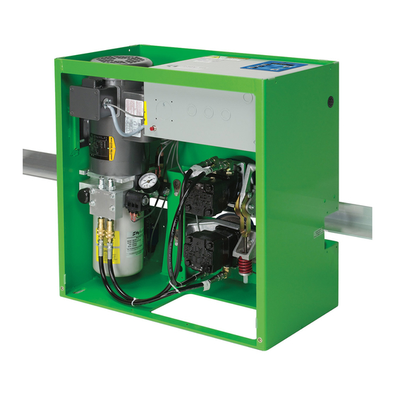
Appendix —Exploded Parts Diagram, Angle View MX001638 See Control Box on page 65. See Pump Pack on page 63. MX000672 MX000387 MX001149 MX000386 MX000690 MX000848 MX001103 Exploded Parts Part Number Part Description MX000387 TOP MOTOR MOUNT MX000690 8" WHEEL AND HARDWARE MX000386 BOTTOM MOTOR MOUNT MX001103... - Page 75 Appendix — Pump Pack MX000989 MX000189 Part Number Part Description Part Number Part Description MX000149 2000 PSI GAUGE MX000686 BREATHER CAP, 0.375" MX000171 VALVE, 8GPM MX000163 RESEVOIR RETURN TUBE, 7" MX000165 ADAPTER FITTING W/ O-RING, -4-2 MX000161 RESEVOIR, 4 QT MX000164 ADAPTER FITTING W/ O-RING, -6-4 MX000160...
-
Page 76: Manual Release Toggle Assembly
Appendix — Manual Release Toggle Assembly MX000801 MX000805 Part Number Part Description MX001103 COMPLETE TOGGLE ASSEMBLY MX000436 TOGGLE YOKE MX000249 TOGGLE HANDLE MOUNT MX000805 MX000434 NUT COUPLER, 3/8-16 MX000433 DRIVE TOGGLE SPRING SEAT MX000432 DRIVE TOGGLE SPRING MX000248 TOGGLE SPRING MOUNT MX000801 MX000435 TENSION SCREW 3.8-16 X 5.5"... -
Page 77: Control Box Electric Enclosure
Appendix — Control Box Electric Enclosure MX000343 MX001036 MX000678 MX000486 MX000487 MX000722 – VFD CONTROLER, 200-240V, 2ft/s MX000723 – VFD CONTROLER, 200-240V, 3ft/s MX000724 – VFD CONTROLER, 380-460V, 2ft/s MX000725 – VFD CONTROLER, 380-460V, 3ft/s MX000638 – VFD CONTROLER, 200-240V, EFO MX000639 –... -
Page 78: Vfd Control Box Layout
Appendix — VFD Control Box Layout CAUTION: DO NOT connect the operator to 110/120V power. The variable frequency drive is not setup to handle the lower, single phase power supply and damage to the unit may occur which is not covered by the Limited Warranty. ©... - Page 79 Appendix — 50VF2-EFO Control Box Layout CAUTION: DO NOT connect the operator to 110/120V power. The variable frequency drive is not setup to handle the lower, single phase power supply and damage to the unit may occur which is not covered by the Limited Warranty. ©...
-
Page 80: 50Vf2/3 Control Box - Stc And Component Wiring
Appendix — 50VF2/3 Control Box – STC and Component Wiring © 2012 Installation and Reference Manual D0125 Rev. H... - Page 81 © 2012 Installation and Reference Manual D0125 Rev. H...
-
Page 82: Slidedriver Wheel Change
Appendix — SlideDriver Wheel Change NOTE: Instructions written for installing wheels with retaining collars. For wheels without collars skip steps 2, 6, 7 and 12. 1. Remove drive wheel assembly from SlideDriver. 2. If the old wheel is equipped with a locking collar, loosen the two 3/16-inch Allen head bolts holding the clamp. - Page 83 Appendix — SlideDriver Wheel Change 5. Locate the new wheel and locking collar. Remove the Cap Screws from the collar. Put blue “thread locker” on the Cap Screws and reinstall them. 6. Place the locking collar on the machined inside hub on the replacement wheel (collar splits between hub splits) and lightly tighten.
- Page 84 Appendix — SlideDriver Wheel Change 9. TIGHTEN BOLT TO APPROXIMATELY 35 – 50*lb. 10. Use a 3/16-inch Allen wrench to tighten the two bolts securely. Be sure the collar is seated against the back of the wheel hub, with the collar splits between the wheel hub splits.
-
Page 85: Limited Warranty
HySecurity gate operator is completely filled If a HySecurity product fails to conform to the warranties in Section 1, Buyer must notify and out and returned to HySecurity within the same 60-day period, the following... - Page 86 All rights reserved. No part of this manual may be reproduced by any means: photocopier, electronic or mechanical, without the express written permission of HySecurity Gate Inc. Additionally, HySecurity Inc. makes no representations or warranty with respect to this manual.
Need help?
Do you have a question about the SlideDriver 50VF2 and is the answer not in the manual?
Questions and answers