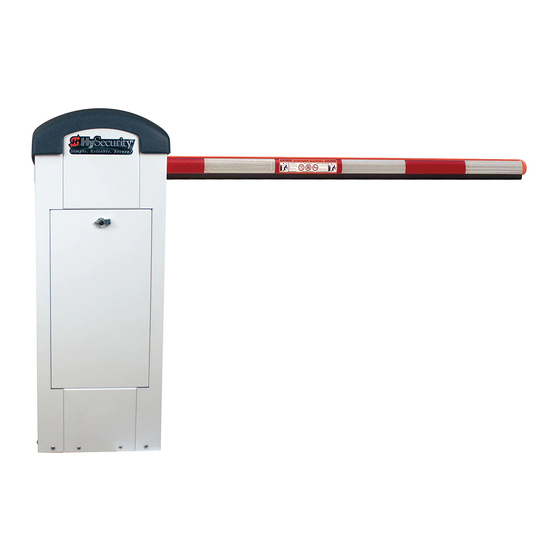
HySecurity StrongArmPark DC 10 Programming And Operations Manual
Pad-mounted electromechanical barrier arm operator with smart dc controller
Hide thumbs
Also See for StrongArmPark DC 10:
- Programming and operations manual (96 pages) ,
- Programming and operations manual (92 pages)


Need help?
Do you have a question about the StrongArmPark DC 10 and is the answer not in the manual?
Questions and answers