HySecurity swingsmart dc 20 Installation And Maintenance Manual
Hide thumbs
Also See for swingsmart dc 20:
- Installation and reference manual (122 pages) ,
- Programming and operations manual (140 pages) ,
- Installation manual (8 pages)
Table of Contents

Related Manuals for HySecurity swingsmart dc 20


Summary of Contents for HySecurity swingsmart dc 20
- Page 1 HySecurity SwingSmart DC 20 Gate Operator SwingSmart DCS 20 Gate Operator Installation and Maintenance Manual D0149 - Revision C Installation and Maintenance Manual (19 October 2010) HySecurity Corporate Headquarters 6623 S 228th Street Kent, WA 98032...
-
Page 2: Swingsmart Components
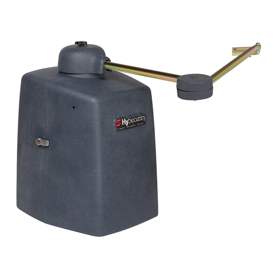
SwingSmart Components WING MART OMPONENTS Stub Arm Swivel Eye Knob, Top Cap Bolt Arm Assembly Cover, Top Cap Handle, Clamp Taper Clamp Assembly Cover, Pinch Limit Plate with Limit Cams Limit Switch Bracket, Limit Switch Transformer Front Cover Gearbox Pulley, Gearbox Brush Belt Control Box... - Page 3 HySecurity provides product installation, maintenance and troubleshooting training. View opportunities online at the HySecurity website: www.hysecurity.com/support. For Technical Support, call 800-321-9947. HySecurity does not share this warranty registration information with third parties unless the requested services, transactions, or legal requirements necessitate it. © 2010...
-
Page 5: Table Of Contents
Contents SwingSmart Components Introducing SwingSmart DC DC C ................I NTELLIGENT EATURES MART ONTROLLER NTRO ..........................I ECHNICAL UPPORT NTRO ........................I NSTALLER HECK NTRO Safety Requirements ....................... S-1 MPORTANT AFETY NSTRUCTIONS Safety Standards - Installer's Responsibility ....................S-1 Safety Standards - Owner/User Responsibility ................... S-3 Hazardous Materials and Proper Disposal .................... - Page 6 Contents Chapter 2: Power ........................2-1 NSTALLING THE ARTH ROUND AC P ............................2-3 IRING OWER Wiring 115VAC Power ..........................2-4 Wiring 230VAC Power ..........................2-4 DC P ..........................2-6 ONNECTING OWER ......................2-6 SING OLAR OWERED PERATOR Design Requirements & Considerations ....................2-7 Connecting the SwingSmart DCS 20 to Solar Power Panels ..............
- Page 7 Contents ....................... 4-9 ONNECTING CCESSORY EVICES Manual Push-button Station ........................4-10 User Relays - Programming Procedure ....................4-11 Chapter 5: Bi-parting Gate Systems ......................5-2 ONNECTING A ASTER LAVE ....................5-2 ASTER AND LAVE IRING ONNECTIONS ........................5-4 ASTER AND LAVE ETUP Chapter 6: Reference...
-
Page 8: Revision C
Contents This page intentionally blank. Contents - 4 SwingSmart Installation and Reference Manual Revision C... -
Page 9: Introducing Swingsmart Dc
Intelligent Features: Smart DC ControllerTM Introducing SwingSmart DC Thank you for purchasing our premium SwingSmart DC™ 20 swing gate operator. At HySecurity® Gate, Inc., we pride ourselves on quality and a number of unparalleled user benefits: Robust - An especially strong twin channel steel chassis and adjustable taper clutch greatly improves the ability for SwingSmart to resist damage from vehicle hits on the gate. -
Page 10: Technical Support
Technical Support ECHNICAL UPPORT For technical support, call your installer or authorized HySecurity distributor. Obtain the serial number of your operator before calling. Refer to SwingSmart Components on the front page. For the name of a distributor near to your locale, call HySecurity at 800-321-9947. -
Page 11: Installer ' S Check List
Set the Close Timer (in the User Menu), if necessary. Check the Smart DC Controller software version. If needed, upload the latest version from www.hysecurity.com. See Smart Touch Analyze and Retrieve Tool (S.T.A.R.T.). Remove the vent plug from the gear box. -
Page 13: Safety Requirements
• A minimum of three years experience installing similar equipment. • Proof of attending a HySecurity Technical Training seminar within the past three years. • Significant manufacturer endorsements of technical aptitude in gate operator installation and operation. Underwriter Laboratories (UL) and the American Society for Testing and Materials (ASTM) are responsible for current safety standards and regulations regarding gate operators and automated gates. - Page 14 Important Safety Instructions • Before attaching the operator to the gate, move the gate in both directions. Make sure it is level and moves freely. A gate that swings easily reduces strain on operator components. Gravity should play no part in the opening or closing of the gate.
-
Page 15: Safety Standards - Owner/User Responsibility
Important Safety Instructions Safety Standards - Owner/User Responsibility WARNING A moving gate can cause serious injury or death. Automatic gate operators move gates with high force. Make sure gates and gate operators are installed to reduce the risks of entrapment. Verify your gate and gate operator comply with UL 325 Safety Standards and ASTM F2200 Gate and Fence Standards. -
Page 16: Hazardous Materials And Proper Disposal
• Observe the polarity between the batteries and charging circuit. • Never mix battery sizes, types, or brands. HySecurity strongly recommends that only sealed AGM style batteries be used. • Exercise care in handling batteries. Be aware that the metal found in rings, bracelets, and keys can conduct electricity, short the batteries, and cause potential injury. -
Page 17: Secondary Entrapment Protection Sensors
Secondary Entrapment Protection Sensors ECONDARY NTRAPMENT ROTECTION ENSORS SwingSmart is equipped with a primary, Type A, inherent entrapment sensor (IES). UL 325 Safety Standard compliance requires installation of secondary entrapment protection sensors, the number of which, depends on the entrapment hazards that exist at each particular installation. To comply with UL 325, the following external sensors may be used: •... -
Page 18: Identifying Gate Operator Category And Usage Class
Secondary Entrapment Protection Sensors Identifying Gate Operator Category and Usage Class The SwingSmart operator, according to UL 325 Safety Standards, falls in the Swing Gate and Vertical Barrier Arm category for gate operators. It’s usage class is determined by the area that the vehicular gate services. Four different vehicular usage classes are defined by UL 325: Class I Class I: Intended for use in a location of one to four single family dwellings or a... -
Page 19: Choosing Secondary Entrapment Protection
E device is permitted as a means of secondary entrapment protection by UL 325 in Class IV applications, but it is not recommended by HySecurity because a buzzer warns, but cannot protect against possible entrapment. HySecurity highly recommends, even for Class IV use, that secondary entrapment protection (edge or photo-eye sensor) devices be installed to detect possible entrapment. -
Page 20: Emergency Stop Button
Emergency Stop Button MERGENCY UTTON An emergency stop button that is accessible from the outside of the operator is a requirement for compliance with UL325 Safety Standards. The red emergency stop button on the SwingSmart operator is located inside a hole cutout on the cover. -
Page 21: Safety Notices
Safety Notices AFETY OTICES The following four levels of safety notices are used where applicable within this manual; each notice contains information specific to the situation. DANGER Indicates death or serious injury will occur if the hazardous situation is not avoided. WARNING Indicates death or serious injury could occur if the hazardous situation is not avoided. -
Page 22: Common Industrial Symbols
Common Industrial Symbols S-10 SwingSmart Installation and Reference Manual Revision C... -
Page 23: Chapter 1: Installation
For your records, take a photograph of the completed installa on site. Secure Side Attach WARNING Signs Figure 1-1. SwingSmart DC 20 SwingSmart DCS 20 Solar Duty cycle: continuous Duty cycle: continuous Power, single phase: Switch selectable... -
Page 24: Pad Condition
Pouring the Concrete 1. Follow the local building codes to identify the frost line and determine the required depth of the concrete pad. HySecurity recommends a minimum Stub out conduit 16-inch (40.6cm) depth with a 4-inches (102mm) minimum 2-inch (51cm) extension above ground above ground level. - Page 25 Pad Condition 21" (53.3cm) minimum 10.5" 26.7cm Output Shaft Center 5.3" (13.4cm) Drill 4 holes for ½" x 3 ½" concrete anchors 10.5" (26.7cm) 5.7" (14.5cm) 14" (35.6cm) 23" (58.4cm) minimum 6" x 7" conduit area 12" (30.5cm) 20" Cover (50.8cm) minimum 2.5"...
-
Page 26: Using An Existing Pad
Pad Condition Using an Existing Pad In many applications, SwingSmart may be a replacement operator for an existing gate system. Make sure the pad is level and inspect the pad for: • Compliance with local building codes. • Appropriate distance from the gate. Refer to Figure 1-3. •... -
Page 27: Unpacking The Operator
Unpacking the Operator NPACKING THE PERATOR Rear cover Front cover Figure 1-4. Prepare the gate operator for installation. See Figure 1-4. 1. Remove the top cap by unscrewing the knob. 2. Unfasten the side cover latches. 3. Remove the front cover. 4. -
Page 28: Mounting The Operator
Mounting the Operator OUNTING THE PERATOR Hinge Center For short gates up to 10 feet (3m): If X = 10.5", Set Y dimension at 14, 18, or 20". (35.6, 45.7, or 50.8cm) For medium gates up to 13 feet (3.9m): Output Shaft Center If X = 12", Set Y dimension at 22, 24, or 28". -
Page 29: Gate Bracket And Linkage Arms
Gate Bracket and Linkage Arms RACKET AND INKAGE Installing the Gate Bracket Short Gate Installation: Photo eye For gates up to 10 feet (3 meters) 14" 23.5" 10.5" 36cm 60cm 27cm 18" 27.5" 46cm 70cm 20" 29.5" 51cm 75cm Medium Gate Installation: For gates up to 13 feet (4 meters) 22"... -
Page 30: Attaching The Stub Arms
Gate Bracket and Linkage Arms Attaching the Stub Arms Taper handle Stub arm Figure 1-8. 1. Attach the swivel eye bolt to the gate bracket using the fasteners provided. 2. Remove the fasteners from the taper clamp assembly. 3. Align the stub arm and secure it to the taper clamp assembly using the fasteners removed in step 2. 4. -
Page 31: Installing The Linkage Arms
Gate Bracket and Linkage Arms Installing the Linkage Arms NOTE SwingSmart operators ship with a standard left-hand linkage arm. The left-hand linkage arm can be used on a right-hand operator (and vice versa) by flipping the arm. This causes the gate attachment point to be approximately 2-inches (51cm) higher which means the gate bracket needs to be positioned accordingly. - Page 32 Gate Bracket and Linkage Arms Tapped hole used for linkage arm adjustments. Elbow Set screw Use the set screw to fine- tune the vertical orientation of the pivot bolt and prevent the arm from locking. Pivot bolt must run Note: The elbow pivot bolt must be parallel with the vertical axis of the operator. If the pivot parallel with the vertical bolt is not vertical, binding of the arm assembly may occur during operation.
-
Page 33: Adjusting The Limit Switches
Gate Bracket and Linkage Arms Adjusting the Limit Switches PUBLIC SIDE Left hand OPEN Right hand OPEN SECURE SIDE Figure 1-12. 1. Determine whether the gate operator is a right-hand operator or left-hand operator. See Figure 1-12. Stand on the secure side of the gate. If the gate opens to the right, it is a right-hand operator. NOTE For a right-hand operator, the OPEN switch is the left limit switch as shown in Figure 1-13 The opposite occurs in a left-hand operator;... -
Page 34: Completing Gate Arm Installation
2. Paint exposed areas to prevent rusting. CAUTION For sites where incident of gate strikes are high, HySecurity recommends setting the elbow with a slight offset at the full close position. Use the supplied set screw to prevent the arm from lock- ing. - Page 35 Gate Bracket and Linkage Arms Top and bottom covers need to be evenly aligned. Gap should be less than ¼-inch. Cover fastener Top cover Elbow joint Bottom cover Cover fastener Figure 1-15. NOTE The two elbow joint cover fasteners are shipped with the covers. 3.
-
Page 36: Articulating Arm Option
• The over-extension stop on the standard HySecurity gate arm does not exist on the articulating arm. To avoid hyperextension, mount the arm so a slight bend at the elbow joint is maintained in the gate closed position. -
Page 37: Setting The Taper Clamp
Gate Bracket and Linkage Arms Setting the Taper Clamp Loosen 45° angle Tighten Taper handle Simulate a gate strike with ~ 100 lbs. of force. Retract Figure 1-16. NOTE Setting the taper clamp with the gate closed impedes traffic flow. If vehicles need to pass through the gate area, delay setting the taper clamp until after the operator has been configured to run. -
Page 38: Removing The Vent Plug
Gate Bracket and Linkage Arms Removing the Vent Plug To complete the installation, be sure to remove the small red vent plug found on top of the gear box. CAUTION Remove the red vent plug prior to leaving the installation site. Removing the red vent plug improves breathability which increases shaft seal life. -
Page 39: Chapter 2: Power
Code (NEC) requires a separate earth ground in addition to the required equipment ground. HySecurity recommends grounding the operator with a separate earth ground connected to a ground rod to assure proper operation and shield it against electromagnetism and other electrical signals that may cause erratic operation with or damage to the Smart DC Controller. - Page 40 Installing the Earth Ground Take the following steps to comply with NEC and NFPA 780 standards: Lug nut 1. Install a grounding rod per local building codes. See Figure 2-1. 2. Attach a large earth ground wire (6AWG) from the grounding rod to the lug nut on the base of the chassis.
-
Page 41: Wiring Ac Power
Wiring AC Power AC P IRING OWER DANGER Turn off AC power at the source (circuit breaker panel) before accessing the wires in the Swing- Smart junction box. Follow facility Lock Out/Tag Out procedures. Make sure both the DC and AC power switches, on the side of the SwingSmart control box are in the off position. -
Page 42: Wiring 115Vac Power
Wiring AC Power Wiring 115VAC Power For standard 115VAC power connection: • Verify AC power supply wires and low voltage (12V & 24V accessory power wires) run through two separate conduits. The higher voltage from the AC power supply may cause interference and anomalies in SwingSmart operation if the high and low voltage wires are routed through the same conduit. - Page 43 Wiring AC Power For the 230VAC power connection: • Verify AC power supply wires and low voltage (12V & 24V accessory power wires) run through two separate conduits as discussed in Wiring 115VAC Power. • Current draw is 1.5 Amps on a dedicated circuit (15A dedicated circuit is recommended). •...
-
Page 44: Connecting Dc Power
OWERED PERATOR HySecurity offers a solar version of the SwingSmart operator: SwingSmart DCS20. The solar model has different internal wiring and includes software programmed for solar use. The Smart DC Controller has a built-in charger which allows a 24V solar panel (or two 12V panels) a direct connection to the SwingSmart operator with no additional electronic devices required. -
Page 45: Design Requirements & Considerations
Using A Solar Powered Operator Design Requirements & Considerations Two standard 8Ah batteries are supplied with SwingSmart DCS 20 and nominally support up to 100 cycles per day based on the following: • Battery storage capacity based on 5 solar hours per day. See Figure 2-7. •... -
Page 46: Connecting The Swingsmart Dcs 20 To Solar Power Panels
Using A Solar Powered Operator Connecting the SwingSmart DCS 20 to Solar Power Panels 1. Use 14 gauge wire or larger to connect the solar panel(s) within 100ft (30.5m) of the operator. Check NEC and local regulations if other distances apply. 2. - Page 47 Using A Solar Powered Operator Control Box DC Battery & Motor switch (OFF) Red spade connector DC Solar Panel switch (OFF) Input & ground wires Figure 2-6. SwingSmart DCS 20 Control Box Revision C Power...
-
Page 48: Connecting Peripherals To Solar Operators
Using A Solar Powered Operator Connecting Peripherals to Solar Operators CAUTION The 24VAC power supply shown in Figure 2-7 is not to be used for peripheral connections because the 24VAC terminals are directly connected to the solar panel inputs. Any peripherals attached to the 24VAC terminals could be severely damaged due to varying voltage levels. -
Page 49: Understanding Gate Activity Based On Solar Zones
Sites requiring more cycles per day or those sites located in less sunny climes, need larger capacity batteries. HySecurity offers a 50Ah battery option which provides six times the storage capacity of the standard 8Ah batteries. -
Page 50: Important Considerations For Dc-Powered Operators
Batteries are rated to perform to capacity at certain temperatures. Variations in temperature affect performance of the batteries. An example of amp hour performance is shown in Table 2-3. HySecurity mounts the battery pack near the transformer to provide residual heat around the batteries which guards against amp hour loss in colder climates. -
Page 51: Installing The Extended Battery Backup Kit
50 Ah Accessory tray Figure 2-9. HySecurity offers extended DC power back up option with two 50Ah batteries. Contact HySecurity parts department to order extended battery backup kit (P/N MX001810). To install the extended battery backup kit: 1. Turn off the DC and AC power switches. - Page 52 11. Using the wires attached in the 1. Start at a gate status 50Ah battery kit, attach the red display. wire to the red positive terminal HYSECURITY GATE CLOSED on the 50Ah battery. Connect its opposite end to the red lead exiting the support tray.
-
Page 53: Chapter 3: Display And Menu Options
START software. NOTE Use a laptop computer at your place of business to conveniently download the free START soft- ware from www.hysecurity.com before heading out into the field. A START User Guide is also available online. •... -
Page 54: Turning Both Power Switches On
Initial Setup Turning Both Power Switches On One AC and one DC rocker power switch are located on the outside edge of the control box. Refer to Figure 3-1. 1. Turn both power switches ON. An audible beep occurs and a red light pulsates next to the OPEN button on the Smart DC Controller which indicates the system is functioning. -
Page 55: Using The Smart Dc Controller Buttons In Menu Mode
Initial Setup Using the Smart DC Controller Buttons In Menu Mode The buttons on the Smart DC Controller let you navigate, change, or clear the information in the display menus. Refer to Figure 3-2. The buttons with text above and below are variable function keys (VFK). Use these buttons to enter or change operational data and navigate through the User and Installer Menus. -
Page 56: Configuring The Setup Menu
5. Continue to configure each menu Note: The GATE CLOSED display that appears. display is an example. HYSECURITY An audible beep occurs as the gate status GATE CLOSED Any one of three gate status display appears when the initial setup is displays could appear depending complete. -
Page 57: Run Mode
The command may come from a variety of sources: a card reader, push- button remote, or recognition of a vehicle passing over a loop detector. In all cases, the operator “runs” the motor when it receives a gate operation command. Understanding Gate Status Displays HYSECURITY HYSECURITY HYSECURITY GATE CLOSED... -
Page 58: Using The Smart Dc Controller Buttons In Run Mode
Fault Mode - errors, faults or alerts appear on the display. Some errors or faults can be reset with the STOP button while more serious faults require the RESET button or cycling power, and then pressing RESET. Faults indicate a need for diagnosis and resolution. Refer to Smart DC Controller Troubleshooting. HYSECURITY GATE CLOSED CLOSE MENU OPEN... -
Page 59: Viewing Operator Status Displays
Run Mode Viewing Operator Status Displays Eight operator status displays appear in two second intervals and show pertinent information which provides a quick overview of the operator’s status or configurations. Refer to Figure 3-6. NOTE Items shown inside the brackets < > are variables that may change depending on operator con- figurations. -
Page 60: User Menu
User Menu The User Menu consists of twelve functions which can be modified using the Smart DC Controller buttons. Refer to Using the Smart DC Controller Buttons In Menu Mode. To access the User Menu, take the following steps: 1. At a gate status display, press the MENU button. CT 0 (OFF) Eight operator status displays scroll past and the CLOSE TIMER... -
Page 61: Adjusting The Close Timer
User Menu Adjusting the Close Timer The close timer assigns how many seconds will pass before the operator initiates closure of a fully opened gate after all open commands and reversing sensor inputs have ceased. Every gate operator needs to have the close timer set to a specific number of seconds unless a hard-wired closing device is connected to the unit such as a push-button station. -
Page 62: Setting The Time And Date
1. At a gate status display, press the MENU button 1. Start at a gate status twice. This accesses the User Menu and the display. HYSECURITY CLOSE TIMER display appears. GATE CLOSED 2. Press NEXT or PREV until the SET CLOCK display appears. -
Page 63: Setting Ac Power Loss Gate Function
User Menu Setting AC Power Loss Gate Function The setting in the AC LOSS display determines what action the operator performs during an AC power loss. The settings help reduce drain on the battery. You can choose between four settings depending on customer preferences. -
Page 64: Adjusting The Display Contrast
User Menu Adjusting the Display Contrast The display contrast can be adjusted from 1 to 9 to increase visibility and ease of use. It is set at the factory to level 5. The text becomes darker as you go up the scale. To adjust the contrast (1 to 9), take the following steps: 1. - Page 65 User Menu Revision C Display and Menu Options 3-13...
- Page 66 User Menu 3-14 SwingSmart Installation and Reference Manual Revision C...
- Page 67 User Menu Revision C Display and Menu Options 3-15...
-
Page 68: Installer Menu
The Installer Menu consists of several functions which can be modified using the Smart DC Controller buttons or configured through the use of a laptop computer and the START software available from the HySecurity website. The Installer Menu options provide more advanced configurations for the SwingSmart operator. Access to the Installer Menu is through the User Menu. -
Page 69: Adjusting The Gate Speed
1. At a gate status display, press the MENU button 1. Start at a gate status twice. This accesses the User Menu and the display. HYSECURITY CLOSE TIMER display appears. GATE CLOSED 2. Simultaneously, press the OPEN and RESET buttons to enter the Installer Menu. -
Page 70: Adjusting The Ies Sensitivity
Installer Menu Adjusting the IES Sensitivity SwingSmart uses a primary Type-A inherent entrapment sensor (IES) per UL325 Safety Standards. A solid immovable object blocking the gate will trip the IES and cause the operator to stop and reverse (for two seconds) and enter safe mode. - Page 71 Examples of conditions which affect IES sensitivity 1. Start at a gate status include:. display. HYSECURITY GATE CLOSED Gate design - A higher IES setting might be required if the gate environment is prone to high winds. If you have gate panels that are open and present little...
-
Page 72: Reinstating Factory Defaults
You can write the settings in a notebook or, if you have a laptop computer, you can use HySecurity’s START software and download the menu settings as part of the diagnostic log. To reinstate factory defaults, take the following steps: 1. -
Page 73: Enabling The Fire Department Override
2. Configure the Installer Menu. 1. Start at a gate status At a gate status display, press the MENU button display. HYSECURITY twice. This accesses the User Menu and the GATE CLOSED CLOSE TIMER display appears. 3. Simultaneously, press the OPEN and RESET... - Page 74 Installer Menu 3-22 SwingSmart Installation and Reference Manual Revision C...
- Page 75 Installer Menu Revision C Display and Menu Options 3-23...
- Page 76 Installer Menu 3-24 SwingSmart Installation and Reference Manual Revision C...
- Page 77 Installer Menu Revision C Display and Menu Options 3-25...
- Page 78 Installer Menu 3-26 SwingSmart Installation and Reference Manual Revision C...
- Page 79 Installer Menu Revision C Display and Menu Options 3-27...
- Page 80 Installer Menu 3-28 SwingSmart Installation and Reference Manual Revision C...
- Page 81 Installer Menu Revision C Display and Menu Options 3-29...
- Page 82 Installer Menu This page intentionally blank. 3-30 SwingSmart Installation and Reference Manual Revision C...
-
Page 83: Chapter 4: Smart Dc Controller
Smart DC Controller Chapter 4 This section provides information about the Smart DC Controller board; its inputs for peripheral connections and its monitoring capabilities. This section explains how to: 1. Review the connections on the Smart DC Controller 2. Perform a Preliminary Test of the components 3. -
Page 84: O Verview Of The S Mart Dc C Ontroller
Overview of the Smart DC Controller DC C VERVIEW OF THE MART ONTROLLER The Smart DC Controller uses LED’s to indicate active inputs when AC power is present. For operators that use only DC power, you can push a button to show the active inputs. This button is at the bottom left corner near the EMERG OPEN input. -
Page 85: Preliminary Testing
Overview of the Smart DC Controller Preliminary Testing All the control device inputs listed in Table 4-1 are shown as a single input. The second wire is connected to a Common Terminal Bus (1 - 8) on the Smart DC Controller board. The Fire Department Open input is an exception and requires a +24 Volt input as well as activation in the Installer Menu. -
Page 86: Vehicle Detector Installation Options
Installing Standard 11-Pin Box Type Vehicle Detectors. HySecurity’s custom HY-5A mini-detector module (Figure 4-3) plugs directly into the Smart DC Controller Board making field installation much faster plus providing a large performance benefit. The detector communicates with the Smart DC Controller microprocessor to achieve the following benefits over common box type detectors: •... -
Page 87: Connecting Hy-5A Vehicle Detectors
Overview of the Smart DC Controller There are four vehicle detector inputs available on the Smart DC Controller as well as via the direct plug in modules. The vehicle detector input functions are as follows: • Free Exit Loop Detector - This opens a fully closed gate. •... - Page 88 Overview of the Smart DC Controller 9. Sensitivity is the only adjustment available on the detector itself. Generally, sensitivity does not need to be increased unless the loop is large or there are multiple loops connected to one detector. NOTE Do not exceed more than 200 square feet (61 square meters) of loop area to one detector.
-
Page 89: Installing Standard 11-Pin Box Type Vehicle Detectors
Overview of the Smart DC Controller 11-P NSTALLING TANDARD EHICLE ETECTORS If standard 11-pin box type vehicle detectors are to be used, perform the following procedure. 1. If there is sufficient space, install the sockets in the control box; if not, then install them in a separate external housing. - Page 90 Overview of the Smart DC Controller PIN 2 PIN 1 24VAC or 24VDC Connect detector to match its voltage rating Inside Outside Free Exit Obstruc on Obstruc on Center Loop Detector Loop Detector Loop Detector Loop Detector LOOP LOOP LOOP LOOP Common CENTER LOOP terminal...
-
Page 91: Connecting Accessory Devices
Connecting Accessory Devices ONNECTING CCESSORY EVICES All accessories require a minimum of two connections on the Smart DC Controller.: • a device input • a Common Bus Terminal (COM) Devices, such as gate edge sensors and photoelectric beams, must be installed to protect against entrapment. These secondary entrapment protection devices are required so the gate installation is in compliance with UL 325 Safety Standards. -
Page 92: Manual Push-Button Station
Connecting Accessory Devices Manual Push-button Station A manual push-button station controls the gate operator and opens, stops, and closes the gate. It is most often used by a guard in a 24-hour guard station. An example of the push-button station connections on SwingSmart is shown in Figure 4-6. -
Page 93: User Relays - Programming Procedure
Connecting Accessory Devices User Relays - Programming Procedure The Smart DC Controller is able to interface with many types of external devices through the use of two user- programmable output relays. All of the user relay functions identified and described in Table 4-3 are accessible in the Installer Menu. - Page 94 Connecting Accessory Devices Table 4-3. User-Programmable User Relays - Function Options (Continued) Name Description Loitering Alert Indicates a vehicle or loitering on the Outside Obstruction Loop. Adjustable from 0 delay to 135 seconds delay in 15-second time intervals. Note: LT - LOITERING ALERT adjustments can be made in the Installer Menu. Gate nearing full travel output Activated when the gate is three feet from full travel in both the open and close directions.
-
Page 95: Chapter 5: Bi-Parting Gate Systems
Bi-parting Gate Systems Chapter 5 The steps involved with installing a bi-parting gate system are explained in this section and include: • Power Requirements • Master/Slave Wiring Connections • Master/Slave Menu Setup Figure 5-1. Revision C Bi-parting Gate Systems... -
Page 96: Connecting A Master Slave Pair
Connecting a Master Slave Pair ONNECTING A ASTER LAVE When installing a dual-operator system, the following must be adhered to: • An electrical conduit for interconnecting wires must span between the two operators. The master-slave communication wires and any low voltage control wires must be installed in a conduit that is separate from the high voltage power wires. -
Page 97: Master And Slave Wiring Connections
Master and Slave Wiring Connections 1. As shown in Figure 5-2, connect a shielded communications cable to the DUAL GATE inputs in each unit. The inputs are located near the base of the Smart DC Controller. Be sure to connect the wires in pairs to the same terminal ports (A-A, B-B, and COM to COM) on both units. -
Page 98: Master And Slave Menu Setup
1. At a gate status display, press the MENU button 1. Start at a gate status twice. This accesses the User Menu and the display. HYSECURITY CLOSE TIMER display appears. GATE CLOSED 2. Simultaneously, press the OPEN and RESET buttons to enter the Installer Menu. Release the... -
Page 99: Chapter 6: Reference
Connecting a Radio Receiver for Remote Open Reference Chapter 6 This section of the manual provides information which may be useful when installing SwingSmart operators. It includes how to: • Connect a Radio Receiver for Remote Open • Install a Gate Locking Mechanism •... - Page 100 Connecting a Radio Receiver for Remote Open Note:This terminal is the same as the input terminal labeled RADIO OPEN along the left edge of the Smart DC Controller. 6. Mount an external antenna onto the top of a fixed fence post near the operator. 7.
-
Page 101: Installing A Maglock Or Solenoid Lock
Installing a MagLock or Solenoid Lock NSTALLING A OCK OR OLENOID To provide additional gate security, a maglock or a solenoid lock can be used and connected to the Smart DC Controller. The Smart DC Controller releases the gate prior to initiating gate movement. Before installing the lock, be sure to: •... -
Page 102: Installing A Lock On 24Vac Systems
Installing a MagLock or Solenoid Lock Installing a Lock on 24VAC Systems To install a lock for 24VAC systems, take the following steps: 1. Connect a wire from COM on USER 1 RELAY and one 24VAC power spade. See Figure 6-3 A ach the power lead from the lock 2. -
Page 103: Setting The User Relay Function In The Installer Menu
Setting the User Relay Function in the Installer Menu 5. Enter the Installer Menu and set the User 1 1. Start at a gate status Relay to Function 6 - GATE LOCK OUTPUT. display. HYSECURITY GATE CLOSED OPEN CLOSE STOP MENU... -
Page 104: Installing Vehicle Detectors And Loops
An advantage of using HySecurity model HY-5A detectors is that problematic “cross talk” is not possible. 3. For greater sensitivity and less chance of false calls caused by the motion of the gate, it is better to use multiple smaller loops, connected in a series circuit, to one detector instead of a single large loop. - Page 105 Figure 6-6. Detector Logic HySecurity recommends that vehicle detectors be used for free open and obstruction sensing logic only. Because of their slower speeds, closing logic is a poor choice for security gate systems. Since there are several ways that the gate may be left standing open and because there is a loss of safety, our circuit has not been designed to accommodate “detect to close”...
- Page 106 Installing Vehicle Detectors and Loops PUBLIC SIDE This layout illustrates a ACCESS CONTROL DEVICE ENTER EXIT bi-direc onal traffic system with (Card reader, etc.) controlled access entry (card reader, radio control, etc.) and a free exit gate. The gate is closed by a TIMER TO CLOSE.
- Page 107 Installing Vehicle Detectors and Loops PUBLIC SIDE ENTER EXIT This layout illustrates a ACCESS CONTROL DEVICE bi-direc onal traffic system with (Card reader, etc.) controlled access entry (card reader, radio control, etc.) and a free exit gate. The gate is closed OBSTRUCTION OBSTRUCTION by a TIMER TO CLOSE.
-
Page 108: Installing Photoelectric Sensors For Secondary Entrapment Protection Only
Installing Photoelectric Sensors For Secondary Entrapment Protection Only NSTALLING HOTOELECTRIC ENSORS ECONDARY NTRAPMENT ROTECTION Emitter Receiver Vehicle Loop (Center Loop) Reflector Entrapment area between open gate and wall Figure 6-9. Refer to Figure 6-9 to help plan the most appropriate placement for the photo eyes being installed as secondary entrapment protection devices. -
Page 109: Operation Notes
Installing Photoelectric Sensors For Secondary Entrapment Protection Only PERATION OTES • A photo eye trip does not reverse gate. • The Smart DC Controller software is factory set to stop upon photo eye trip. • Software is configurable to stop and reverse two seconds upon photo eye trip. •... -
Page 110: Supervised Connection
Photo eyes usually provide alignment aid LED's for this setup, but they can be hard to see. HySecurity has provided a unique feature that turns power on to the photo eyes and causes our buzzer to chirp when the photo eyes enter and exit alignment. - Page 111 Installing Photoelectric Sensors For Secondary Entrapment Protection Only Notes about retro-reflective systems: Correct installation and alignment of a retro-reflective photo eye and its reflector is important for trouble free performance. Any system operating at a range greater than 16 feet is more prone to false triggering due to dirty optics, condensation or poor weather.
-
Page 112: Installing Gate Edge Sensors
Installing Gate Edge Sensors NSTALLING ENSORS 3-sided edge sensor on the 3-sided edge sensor on the bottom edge of the gate.* leading edge of the gate. *Required for UL325 compliance if gate’s bottom edge is 6-inches (15cm) more above ground level. Figure 6-11. - Page 113 Installing Gate Edge Sensors Edge sensors that are not attached to the Edge Sensor moving gate, such as post mounted sensors, STOP must be wired in parallel and directly OPEN connected to the gate operator: CLOSE OPEN • If the gate is swinging open to a wall with P ARTIAL OPEN less than 16 inches (41cm) of clearance,...
-
Page 114: Smart Dc Controller Troubleshooting
Audio Alert buzzer sounds distinctive chirps. Any alerts, faults or errors are also logged into memory and date/ time stamped. For diagnostic purposes these messages can be retrieved with optional START software available from HySecurity. Refer to Smart Touch Analyze and Retrieve Tool (S.T.A.R.T.). - Page 115 Smart DC Controller Troubleshooting Revision C Reference 6-17...
- Page 116 Smart DC Controller Troubleshooting 6-18 SwingSmart Installation and Reference Manual Revision C...
- Page 117 Smart DC Controller Troubleshooting Revision C Reference 6-19...
- Page 118 Smart DC Controller Troubleshooting 6-20 SwingSmart Installation and Reference Manual Revision C...
- Page 119 Smart DC Controller Troubleshooting Revision C Reference 6-21...
- Page 120 Smart DC Controller Troubleshooting 6-22 SwingSmart Installation and Reference Manual Revision C...
-
Page 121: Vehicle Detector And Loop Fault Diagnostics
Smart DC Controller Troubleshooting Vehicle Detector and Loop Fault Diagnostics If HySecurity HY-5A vehicle detector modules are used, the Smart DC Controller has the ability to store and report detector and loop fault information for performance diagnostics. If the Smart DC Controller senses a loop or detector problem: •... - Page 122 Errors can be retrieved from the Smart DC Controller by downloading from the RS232 communications port or the USB port. HySecurity's free START software, a PC computer, and a special download cable or USB cable are required to retrieve and read this data.
-
Page 123: Swingsmart Schematics
Smart DC Controller Troubleshooting SwingSmart Schematics Figure 6-13 and Figure 6-14 illustrate the schematics for SwingSmart DC 20 and SwingSmart DCS 20. Figure 6-13. SwingSmart DC 20 Schematics Revision C Reference 6-25... - Page 124 Smart DC Controller Troubleshooting Figure 6-14. SwingSmart DC 20 Solar Schematics 6-26 SwingSmart Installation and Reference Manual Revision C...
-
Page 125: General Maintenance
ENERAL AINTENANCE Smart Touch Analyze and Retrieve Tool (S.T.A.R.T.) HySecurity provides Smart Touch Analyze and Retrieve Tool (START) software to help HySecurity gate operator users and installers conduct the following field service activities: • Configure installer and user menu settings •... -
Page 126: Setting User Account Controls
9. 8. Follow the step-by-step instructions to complete the installation. 9. When the download is complete, log out of the HySecurity website. Shortcuts for the START and Smart Touch Controller History Logs appear on your laptop’s desktop. -
Page 127: Mechanical Maintenance
General Maintenance Mechanical Maintenance CAUTION Before checking the internal mechanisms of the operator, turn off all power switches. The SwingSmart mechanical maintenance is not in depth or difficult, but should be performed on a routine basis. The operator chassis is zinc plated, but some environments may speed corrosion of this plating. Schedule regular maintenance and look for the following: •... -
Page 128: Drive Belt Tension And Alignment
General Maintenance RIVE ENSION AND LIGNMENT To adjust the tension or 1/16" - 1/8" replace the belt, loosen 2 fasteners. Retighten the fasteners when Slide the motor adjustments are bracket. complete. Figure 6-16. Proper drive belt tension is important for prolonging the life of the drive belt and maintaining the superior performance of the operator. -
Page 129: Dc Battery Replacement
General Maintenance DC B ATTERY EPLACEMENT HySecurity provides a one year warranty from the date of shipment for the all batteries supplied with the SwingSmart operator. Indicators of a low battery include: • LOW BATTERY or DEAD BATTERY appears on the Smart DC Controller display which may or may not be indicative of normal discharge. -
Page 130: Clock Battery Replacement
General Maintenance 6. Remove the first battery from the support tray. 7. Slide the second battery to the right, disconnect the red and black wires and remove it from the tray. To install the two new batteries, reverse the removal procedure. 1. -
Page 131: Parts & Limited Warranty
Parts & Limited Warranty WING MART ARTS Rod End Knob, Top Cover Arm Assembly Cover Handle, Clamp Covers, Arm Clamp Assembly Limit Plate & Blocks Limit Switch Kit Bracket, Limit Swith Transformer Gearbox Pulley, Gearbox Belt, Drive Cover Cover Battery Kit, 8AH Pulley, Motor Motor Battery Kit, 50AH... -
Page 132: Wing Smart Arts
WING MART ARTS Part Name Part Number SwingSmart Models Arm Assembly, Articulating MX002011 Arm Assembly, Left Hand MX002010 Arm Assembly, Right Hand MX002009 Battery Kit, 50AH, Replacement MX002013 Battery Kit, 8AH, Replacement MX002008 Belt, Drive, SwingSmart MX001744 Board, Power Supply, 115/230VAC MX001766 Board, Smart DC Controller, SwingSmart MX001457-1... -
Page 133: Limited Warranty
Buyer's Exclusive Remedies for Any Nonconformity. remain serviceable for the following periods: If a HySecurity product fails to conform to the warranties in Section 1, Buyer must Hydraulic Gate Operators: Five Years or 500,000 gate cycles (whichever notify and order replacement parts from the Distributor through which the product was... -
Page 134: Swing Smart Dc Specifications
Additionally, HySecurity Gate Inc. makes no representations or warranty with respect to this manual. We also reserve the right to make changes in the products described without notice and without any obligation to notify any persons of any such revision or change.
Need help?
Do you have a question about the swingsmart dc 20 and is the answer not in the manual?
Questions and answers