Table of Contents
Advertisement
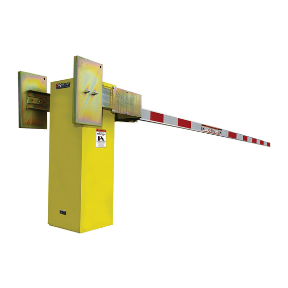
StrongArm – Quick Start Instructions
These instructions are provided as a quick reference guide to the experienced installer that is already familiar with
all safety precautions and the installation of this gate operator. Do not attempt to install from this guide if you are
inexperienced with this product.
Using four 1/2" x 4 1/2" anchor bolts mount the operator to a concrete slab which reaches below the local
1.
frost line. If necessary, use shims to level the base.
2. If installing the DC version of the operator, be careful to mount the battery power supply box very near the
control enclosure because of the high current demand by the DC motor. Note: For the DC version, refer
to Section 8 of the operator handbook.
Connect the electrical power to loose wires from the On/Off switch and a grounding wire to the lower left
3.
corner of the electrical panel. Be certain the labeled voltage and phase of the operator matches the
available supply.
Turn on the power switch. The Smart Touch LCD display should show, after a 2-second delay, the
4.
characters [uC_0]. This is a setting for the UL user class that must be made before any function will be
possible. Press the Select button, then the Next button and change the 0 to be class 1-4 as appropriate
for the site. Press the Select button again to lock the setting.
Press the Menu button and the display will jump to the close timer setting [Ct_0]. If a close timer function
5.
is needed, set in the same manner as above. Press the Menu button again to exit to the Run Mode. The
LCD display should now read StoP, CloS or OPEn.
If the operator contains more than four counterweights per side, the arm must be mounted before the
6.
gate operator can be allowed to function. Otherwise, test for normal operation of the gate.
Install the barrier arm and clamp securely. Single arms, up to 18' maximum can be installed on either the
7.
left or right side of the operator. Arms longer than 26' include anti-sway cable harnesses that must also
be attached.
Run the operator and verify normal smooth operation. If the arm stops abruptly at the end of travel, it
8.
may be necessary to adjust either of the open or close brake valves and/or a limit switch setting. There
are two brake valves on the pump manifold and the one closest to the motor controls the stopping of the
arm in the closing direction. The open direction stop control is with the brake valve just to the left. If
adjustment of either brake valve is necessary, loosen the 9/16" lock nut and turn the adjuster screw with
an Allen wrench. A CCW adjustment will stop the arm more quickly. The limits must be set to trigger
about 10 degrees of arc before the arm has reached full travel. If adjustment of the limit switches is
necessary, slightly loosen the set screws on the cams at the top of the operator and set the limits to trip
early enough to ensure a smooth stopping arm. For detailed instructions on barrier arm adjustments,
review the page titled HTG 320 Adjustments in the handbook.
Connect any required accessory device wiring. Note that the various inputs are all one wire only to the
9.
main terminal strip while the other wire connects to the Common Buss on the nearby power supply board.
10. To access the User menu in the Smart Touch Controller, simply press the Menu button while there is no
active Open or Close input. The display will scroll system values and stop at the [Ct__] close timer
setting. There are 12 menu items in the User Menu. To reach the more detailed Installer menu, the
system must be in the User Menu first, then simultaneously press Open and Reset. The display will go to
[uC__] which is the first of 32 items in the Installer Menu. Read the instructions before attempting any
adjustments!
For HTG Barrier Arm Gates
Advertisement
Table of Contents

Related Manuals for HySecurity HTG 320-2


Summary of Contents for HySecurity HTG 320-2
- Page 1 StrongArm – Quick Start Instructions For HTG Barrier Arm Gates These instructions are provided as a quick reference guide to the experienced installer that is already familiar with all safety precautions and the installation of this gate operator. Do not attempt to install from this guide if you are inexperienced with this product.
- Page 2 Installation and Maintenance Manual Smart Touch Controller Menu Guide for the HTG 320 To gain access to the User Menu, press the Menu button when the gate is stopped. The LCD will scroll through key several items, then stop at the close timer setting [Ct ]. User Menu Options Default Description...
- Page 3 HySecurity Gate Operators HYDRAULIC BARRIER ARM GATE Operators With Smart Touch Controller Installation and Maintenance Manual Models HTG 320-2, HTG 320-3 HTG 320-6, HTG 320-8 DC Battery UPS version Phone: 800-321-9947 FAX: 888-321-9946 Internet: www.hysecurity.com Email: Info@hysecurity.com...
- Page 4 Installation and Maintenance Manual Barrier Arm Gate Operator © ©Copyright 2001 Hy-Security Gate Inc. All rights reserved. No part of this manual may be reproduced by any means: photocopier, electronic or mechanical, without the express written permission of Hy- Security Gate Inc. Additionally, Hy-Security Inc. makes no representations or warranty with respect to this manual.
-
Page 5: Table Of Contents
Installation and Maintenance Manual Table of Contents Introduction ........................v Warranty Registration..................... vi Available Models and Features ..................1-2 I. Safe Gate Design Important Information for Gate System Installers, Owners & Users .......3-5 II. Installation Typical System Schematic for a Barrier Gate..............5 Tools Required ......................... - Page 6 Table of Contents, continued V. Detectors and Loops Loop & Detector Installation Guide ................. 33-35 Vehicle Detector Options....................36 HySecurity Hy-5A Vehicle Detector Installation ............37 Standard 11-Pin Vehicle Detector Installation ............. 38 Detector & Loop Fault Diagnostics................39 VI. Accessories 24 Hr / 7 Day Time Clock Option ..................
-
Page 7: Introduction
When the installation is complete, leave this manual for the owner’s use and reference. Please do not hesitate to give your HySecurity distributor a call if you experience any difficulties during the installation. They are experienced and trained to assist in resolving any problems. -
Page 8: Warranty Registration
Installation and Maintenance Manual For warranty registration, please fill in this information, fax or mail a copy to HySecurity, then give this manual to the owner of the gate operator. Owner Name: ____________________________________________ Address: ________________________________________________ City, State, Zip: ___________________________________________ Telephone number: ________________________________________... -
Page 9: Available Models And Features
All models employ a time delay Soft Stop system. Additionally, brake valves (shown at right) are used to control the smooth stopping of the gate. These valves are exclusive to HySecurity’s operators. They are independently adjustable to allow the gate to stop predictably without banging. Starting the Gate When starting very heavy barrier arms, it is necessary to Soft Start the load gently, in addition to stopping it smoothly. - Page 10 The Smart Touch Controller (Standard) This is the brain of the all HySecurity’s automatic operators. Truly high technology, but is also very rugged to reliably serve in the harsh environments that exist in the real world. The Smart Touch Controller is also very smart and can quickly be configured by an installer or user to adapt to about any functional requirement of a specific site.
- Page 11 Installation and Maintenance Manual READ THIS FIRST! Important Information – Review Before Installation Automatic gate operators provide convenience and security to users. However, because these machines can produce high levels of force it is important that all gate operator system designers, installers and end users be aware of the potential hazards associated with improperly designed, installed or maintained systems.
- Page 12 Installation and Maintenance Manual Install An Automatic Barrier Arm Gate Operator Only When: The operator will be properly electrically grounded and the intended supply voltage matches the voltage label on the operator. The controls that operate the gate have been mounted far enough away from the moving gate such that users cannot touch the gate while operating the controls.
-
Page 13: Important Information For Gate System Installers, Owners & Users
Installation and Maintenance Manual Important Information for Gate System Owners & Users WARNING: To reduce the risk of serious injury or death, read and follow all instructions in the gate operator handbook and on the warning labels. Save These Important Owner and User Instructions: (Installers –... -
Page 14: Tools Required
Installation and Maintenance Manual Tools Required for an Efficient Installation 1. Chalkline or other 2. Carpenters 3. Concrete anchor 4. Allen wrench set 5. Hammer builders string pencil or crayon bolts, four " x 4" 6. Screwdriver sets, 7. Wrench set, open end, 8. -
Page 15: Installation Preparations And Installation
Keep in mind that a space of 7 X 11” just inside of the operator door is where the conduits must enter into the operator. HySecurity recommends a slab reaches below the local frost line. See the footprint plan and elevation view on pages 13-15. - Page 16 Installation and Maintenance Manual Installation 4. Electrical power Connection This operator is intended for permanent installation, so all electrical conduits must be properly connected to the control box. The entry for the primary power is a ½ - ¾” knockout on the left side of our control box next to the on- off switch.
- Page 17 Installation and Maintenance Manual Installation Attaching Barrier Arms To The Operator 1. Bolt arm(s) to operator. The maximum length for a single wood board is 14' length. Wood arms that are longer than 14' must be twin arms bolted together near the tip. 2.
-
Page 18: Htg 320 Components
Installation and Maintenance Manual Components of the Barrier Arm Gate Operator... -
Page 19: Htg 320 Adjustments
Installation and Maintenance Manual HTG 320 Adjustments The HTG 320 gate operator is pre-adjusted at the factory to perform correctly with the barrier arm shipped. If the arm length, or weight is changed, it may be necessary to re-adjust the gate operator to perform correctly. -
Page 20: Manual Operation
Installation and Maintenance Manual HTG 320 Manual Operation A bypass valve has been provided that can override the hydraulic lock that normally secures the arm from being lifted. In the event of a power failure, manual operation is achieved through the following procedure. -
Page 21: Technical Drawings
Installation and Maintenance Manual 46 ¾”... - Page 22 Installation and Maintenance Manual 46 ¾...
- Page 23 Installation and Maintenance Manual...
-
Page 24: Basics Of Using The Smart Touch Controller
Installation and Maintenance Manual Basics of Using the Smart Touch Controller System Read this page if you are unfamiliar with using the Smart Touch Controller. You must learn to navigate and change menu settings within the Smart Touch Controller before an installation can be completed or any control settings or function changes can be made. -
Page 25: Installation Configuration For Smart Touch Controller
Installation and Maintenance Manual c. The LCD display scroll will stop at the menu item for the auto close timer setting [Ct __]. This is the first item in the User Menu. d. To access the more detailed Installer Menu, the system must first be in the User Menu, and then simultaneously press the Reset button and the Open button. -
Page 26: Wiring Control Inputs To The Smart Touch Controller
Installation and Maintenance Manual Wiring Control Inputs to the Smart Touch Controller 1. Test open and close before wiring the external control inputs. This makes it easier to troubleshoot if an unexpected functionality arises. “New Generation” Smart Touch Operator inputs (after Sept. 2006) use an LED to indicate when it is active. - Page 27 Installation and Maintenance Manual “New Generation” Smart Touch Board LEDs showing active input circuits now always enabled except for DC machines (during AC loss) Connector to Power Connector Runs software SlideWinder Drive Board 4.xx and higher RS 485 Future Expansion (new) UNUSED INPUTS Motor Relay...
-
Page 28: Connecting A Master/Slave Pair
Installation and Maintenance Manual Connecting a Master / Slave Pair Configuring two operators to be a Master & Slave pair is easy with the Smart Touch Controller. There is no need to order a special model or any adapters. The area of the board marked Dual Gate employs a 3-wire RS485 serial port for communication between Master &... -
Page 29: Table Of User And Installer Menu Functions
Installation and Maintenance Manual Smart Touch Controller User Menu Settings for HTG Initial Power Up – When power is turned on, the display will disclose the software revision: Display Revision Number 2s delay Displays software version Number, ex. [h3.02] System Data and accessing the User Menu Settings: If the gate is stopped in normal mode, pressing of the Menu button accesses the User Menu. - Page 30 Installation and Maintenance Manual Smart Touch Controller Installer Menu Functions The Installer Menu can be accessed only by entering the User Menu first, and then by pressing the Reset button and the Open button simultaneously (some older software requires the Reset button be pressed first and held while the Open button is pressed).
-
Page 31: User Menu: Description Functions Available
Installation and Maintenance Manual Description of Functions Available in the User Menu User 1 [Ct _] Close timer setting: This menu item is the automatic close timer for the gate. The factory setting is zero, which is off. It may be configured up to 99 seconds. User 2 [hC 0] Momentary Close: This menu item is to configure for the system for constant hold push button Close function. -
Page 32: Installer Menu: Description Functions Available
Installation and Maintenance Manual Description of Functions Available in the Installer Menu [uC 0] Set UL Usage Class: This menu item is used to set the UL usage class, which must be Installer 1 set by the installer before the operator will function. See page 17, step 2. Installer 1a [bu 0] Select Buzzer Type: This menu item selects the type of audible buzzer installed on the machine. - Page 33 Installation and Maintenance Manual Description of Functions Available in the Installer Menu Installer 15 [tC 1] Time clock / Interlock input: This menu item configures the input at terminal #7 to be either for the gate interlock function or for an external time clock to open input. The default setting is [tC_1] for the interlock function.
-
Page 34: Options For User Programmable Output Relays
Installation and Maintenance Manual Programmable Output Options for User Relays 1–3 The Smart Touch Controller can be set to interface to many types of external devices through the use of its programmable output relays. All of the output functions listed below are accessible in the Installer Menu under the selection [r1 __], [r2 __] and [r3 __]. -
Page 35: Clock Functions
Use a DL 2025 / DL 2032 or CR 2025 / 2032 battery. * START Configuration and Diagnostic software is available at no charge from our website – www.hysecurity.com. Serial communication cables (P/N ESR00024) as well as Serial to USB adaptors (if needed) are available through... -
Page 36: Entrapment Protection
UL325 standard that states: “any vehicular barrier arm that is not intended to move toward a rigid object closer than 2 feet does not require protection for entrapment.” HySecurity recommends that the designer and installer employ the use of a gate edge and a photo eye in the event... -
Page 37: Ul 325 Standard Requirements For Entrapment Protection Devices
Installation and Maintenance Manual UL 325 Standard requirements for Entrapment Protection Devices Gate Operator Category Horizontal Slide, Vertical Lift, Vertical Pivot Swing and Vertical Barrier (arm) Primary type a Secondary type a Primary type a Secondary type a Usage class Vehicular I and II 1, B2, or D A, or C... -
Page 38: Placement And Use Of Secondary Pedestrian Entrapment Sensors
Installation and Maintenance Manual Placement and Use of Secondary Pedestrian Entrapment Sensors To reduce the risk of serious injury or death, read and follow all instructions in the WARNING: gate operator handbook and on the warning labels. Automatic gate operators are intended only for vehicular use and pedestrians must be routed to a separate man gate, however sensors are still required in order to provide a degree of protection should anyone happen to stray into the area of an automatic gate. -
Page 39: Installing Photoelectric (Non-Contact) Sensor
A requirement of the UL 325 standard is that a photoelectric sensor be laboratory tested and “recognized” under UL 325. In order to be compatible with a HySecurity operator, a photo eye must be rated to function from 24 Volts DC source power. - Page 40 Photo eyes usually provide alignment aid LED’s for this setup, but they can be hard to see. HySecurity has provided a unique feature that causes our buzzer to chirp when the photo eye enters and exits alignment. See User menu 9. Set the Installer menu item [PE_0] to [PE_1] and the buzzer will provide an audible indication both when the beam is broken and remade.
-
Page 41: Detectors And Loops Loop & Detector Installation Guide
An advantage of using HySecurity model HY-5A detectors is that problematic “cross talk” is not possible. 4. To avoid interference, keep loops at least two (2) inches above any reinforcing steel. Do not route loop wires with, or in close proximity to, any other conductors, including other loop leads, unless shielded lead-in cable is used. - Page 42 Detector Logic HySecurity Gate Operators recommends that vehicle detectors be used for free open and obstruction sensing logic only. The exception is in parking applications with our HTG 320 barrier arm operator where a reset detector may be also used to close the gate.
- Page 43 Installation and Maintenance Manual...
-
Page 44: Vehicle Detector Options
Standard box type 11 pin (24 Volt DC or 24 Volt AC) vehicle detectors may be connected in the traditional manner, see page 38. HySecurity also offers a custom mini detector module that plugs directly into the Smart Touch Control board. Not only is the field installation much faster, but there is also a large performance benefit. -
Page 45: Hysecurity Hy-5A Vehicle Detector Installation
Installation and Maintenance Manual HySecurity Hy-5A Vehicle Detector Installation 1. Insert the locking end of each of two 1” long white plastic standoffs into the mounting holes on the detector. 2. Plug the detector into the appropriate socket along the right side edge of the Smart Touch Controller board for the detector function that is desired. -
Page 46: Standard 11-Pin Vehicle Detector Installation
Installation and Maintenance Manual Standard 11 Pin Box Type Vehicle Detector Installation 1. If standard 11 pin vehicle detectors are to be used, snap up to three sockets onto the aluminum DIN mounting rail, with the key in the center hole facing to the left. Mount on the shelf near the top of the operator and wire as shown below. -
Page 47: Detector & Loop Fault Diagnostics
Installation and Maintenance Manual Detector & Loop Fault Diagnostics If HySecurity HY-5A mini detector modules are used, the Smart Touch Controller has ability to store and report detector and loop fault information for performance diagnostics. If The Smart Touch Controller senses a loop or detector problem, the LCD display will flash the abbreviation for the affected detector (ELd –... -
Page 48: Accessories 24 Hr / 7 Day Time Clock Option
Installation and Maintenance Manual 24 hr 7 day Timer Connection to Smart Touch Controller... -
Page 49: Connecting A Radio Receiver
Installation and Maintenance Manual Connecting a Radio Receiver for Remote Open Mount a commercial style 24-Volt radio receiver (external antenna type) on the inside of the operator, below the electrical box. Knock out the smallest hole in the lower right corner of the electrical box and route the wires to the area marked Radio Options. - Page 50 Installation and Maintenance Manual Troubleshooting Guide, HTG 320 Gate Operators Important Note: If the manual bypass valve is open, the electric motor will run, but nothing will move. See the drawing on page 10 to locate the bypass valve. To close the valve, twist to allow the knob to re-engage. Electrical Problems in General: The Smart Touch Controller reports system malfunctions on its LCD display and the buzzer will emit a series of chirps at defined intervals.
-
Page 51: Troubleshooting
HySecurity distributor. Extremely cold weather is unlikely to seriously affect the speed of the gate, because HySecurity employs a special grade of hydraulic oil that we call UNIFLOW oil, which maintains a very linear viscosity over a broad range of temperatures. Because of this high quality oil and other design considerations, we rate our operators for service in ambient temperatures of –40F degrees to 130F degrees. -
Page 52: Maintenance
It has an adjusting head and lock nut. To adjust, loosen the lock nut and screw the threaded bolt clockwise for increased pressure, counterclockwise to decrease pressure. MODEL FACTORY RELIEF SETTING HTG 320-2 700 PSI HTG 320-3, -6, -8 Models 1000 PSI... - Page 53 *8 DC Operators use DC motors with carbon brushes which wear in normal operation. Worn brushes can damage the DC motor. Under severe conditions HySecurity recommends that brushes be checked after 2 years and the replacement interval be adjusted as necessary.
-
Page 54: Two Part Operators (Battery Types) Important Notes About Dc Powered Gates
HySecurity uses a permanently sealed type battery, which needs no maintenance over its life span. A low voltage-sensing circuit protects the batteries from damage which could be caused by over-discharge. -
Page 55: Dc Wiring & Control
Installation and Maintenance Manual Wiring and Control Configuration for DC Operators If this installation is a 24-Volt DC battery type gate operator, there are a few additional steps that must be completed before the system can be functional. Review the installation instructions on page 8 and the connection diagram on page 49. -
Page 56: Battery Supply Diagrams
Installation and Maintenance Manual D.C. POWER BATTERY PACK 2 BATTERY, 110AH; 30”H X 30”W X 12”D... - Page 57 Installation and Maintenance Manual 24V 110A.H. BATTERY POWER SUPPLY FOR DC OPERATORS...
-
Page 58: Appendix Wiring Size Schedules
Installation and Maintenance Manual Wire Size Schedules For 1/2-hp through 5-hp motors Supplying a gate operator with the right electrical service is crucial to the way the performance of the operator the life of its electrical components. If the wire size used is too small, the voltage loss, especially during motor starting, will prevent the motor from attaining its rated horsepower. - Page 59 Installation and Maintenance Manual...
-
Page 60: Components & Replacement Parts
Installation and Maintenance Manual Parts Breakout... - Page 61 Installation and Maintenance Manual Parts Breakout...
- Page 62 Installation and Maintenance Manual Parts Breakout – AC Pumps MX000234 HVABY 000 CRT...
- Page 63 Installation and Maintenance Manual Parts Breakout – DC Pumps MX000234 HVABY 000 CRT...
- Page 64 Installation and Maintenance Manual Parts Breakout...
- Page 65 Installation and Maintenance Manual Parts Breakout ITEM # HVAFL NVA 1 ea. HVACK CDAD XBN 1 ea. HVACK CVB 1 ea. MX000234 2 ea. 3-10 HVABY 000 CRT 1 ea. 3-11 HSFFI 714 CS04 5 ea. 3-13 HSFFI 850 0404 1 ea.
- Page 66 Installation and Maintenance Manual Parts Breakout – DC Power Supply Battery Pack Components PART NUMBER ESWCB 030 60 1 EA. ESWOI 067 DCEX 1 EA. ECOTS 1102 1 EA. EENEN HOI 3030 1 EA. EDCBY 12B 090 2 EA. ECOTS 005 1 EA 2-10 ESWFU 010 15 1 EA...
-
Page 67: Smart Touch Controller Connections
Installation and Maintenance Manual Smart Touch Controller Connections... -
Page 68: Quick Strongarm Brake Valve Adjustment Procedure
Installation and Maintenance Manual Quick StrongArm Brake Valve adjustment Procedure... -
Page 69: Limited Warranty
Buyer's Exclusive Remedies for Any Nonconformity. sale each of its products will, in all material respects, conform to If a HySecurity product fails to conform to the warranties in its then applicable specification and will be free from defects in Section 1, Buyer must notify HySecurity within a reasonable time material and manufacture.
Need help?
Do you have a question about the HTG 320-2 and is the answer not in the manual?
Questions and answers