HySecurity HydraSwing 40 Programming And Operations Manual
Hydraulic swing gate linear actuator with smart touch controller
Hide thumbs
Also See for HydraSwing 40:
- Programming and operations manual (140 pages) ,
- Installation instructions manual (8 pages) ,
- Programming and operations manual (136 pages)

Related Manuals for HySecurity HydraSwing 40


Summary of Contents for HySecurity HydraSwing 40
- Page 1 Programming and Operations Manual HydraSwing ™ 40, 40 F , 40 Twin, 80 F , 150 Hydraulic swing gate linear actuator with Smart Touch Controller • www.hysecurity.com 800-321-9947...
- Page 3 HydraSwing ™ HydraSwing 40, 40F, 40 Twin, 80F, and 150 Programming & Operations Manual with HySecurity Smart Touch Controller This document provides Important Safety Information, specifications, and references along with an overview of programming user and installer menu options, designing vehicle loop layouts,...
- Page 4 Base of cylinder Cylinder Bearing (2x) Brake valves Chassis with mounting holes Rod end Brake manifold (clevis end) Manual release assembly Hoses with Quick Disconnects HydraSwing 40, 40F and 40 Twin D0557 Rev. B HydraSwing Programming & Operations www.hysecurity.com...
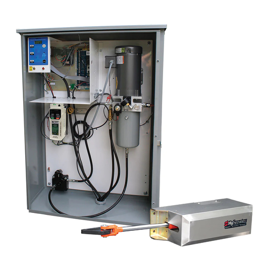
- Page 5 HydraSupply Components Smart Touch Controller Smart Touch Controller Power board display and keypad Motor Reset button (external) Control box Pump pack assembly Variable Speed Drive Ground lug location in cabinet Grade level Conduit Ground rod www.hysecurity.com Introduction D0557 Rev. B...
- Page 6 HydraSwing Pump Pack Components Inherent Entrapment Sensor (IES) Pressure relief valve Filler plug Reservoir Vent plug Breather cap Pressure gauge Open valve Solenoid Quick Disconnects D0557 Rev. B HydraSwing Programming & Operations www.hysecurity.com...
-
Page 7: Table Of Contents
Adjusting the Pressure Relief Valve ..........................21 The Inherent Entrapment Sensor (IES) ..........................22 Manufacturer’s responsibility ............................22 Pressure Relief Valve – All Hydraulic Operators: ......................22 Inherent Entrapment Sensor – (IES) ...........................23 ModBus RTU in HydraSwing ............................23 www.hysecurity.com Table of Contents D0557 Rev. B... - Page 8 User Relays – Programming Procedure ..........................47 Hy8Relay: Extended Relay Module Option........................49 Vehicle Detector Logic ..............................50 TailGate Alert ................................50 Anti-TailGate Mode Selection .............................50 Vehicle Detector Installation: HY-5A ..........................51 Connecting HY-5A Vehicle Detectors ..........................52 D0557 Rev. B HydraSwing Programming & Operations www.hysecurity.com...
- Page 9 Clock Battery Replacement ............................76 Mechanical Maintenance ...............................77 Hydraulic System Maintenance ............................77 Brake Valve Adjustments ............................78 Pressure Relief Valve Adjustments ..........................79 Open Valve .................................79 HydraSwing Hydraulic Cylinder Maintenance ......................79 HydraSwing Operator Maintenance Schedule .......................80 Specifications .................................82 www.hysecurity.com Table of Contents D0557 Rev. B...
- Page 10 D0557 Rev. B HydraSwing Programming & Operations www.hysecurity.com...
-
Page 11: Welcome To Hysecurity
Our commitment to quality and innovation will become evident as the features and performance of the expertly engineered and manufactured HydraSwing gate operator become familiar to you. Thank you for the confidence you’ve shown in becoming part of the HySecurity family and in choosing a premium, industry-leading product. HySecurity Gate, Inc. Headquarters in Kent, WA www.hysecurity.com... -
Page 12: Contact Information
Qualified HySecurity distributors are experienced and trained to assist in resolving any problems. For the name of a qualified distributor near you, call HySecurity at 800-321-9947. Before contacting your distributor or HySecurity Technical Support, obtain the serial number of your operator. -
Page 13: Important Safety Information
HySecurity product manuals. It is important that only qualified installers handle the installation of the HySecurity equipment and gate operator. A “qualified” installer has one of the following: •... -
Page 14: Safety - Additional Installer Responsibility
Š Physical stops must exist in the gate construction to prevent over-travel in both directions and, for slide gates, guard posts must be installed to prevent the gate from falling in the event of a roller failure. D0557 Rev. B HydraSwing Programming & Operations www.hysecurity.com... -
Page 15: Safety - Additional Installer Responsibility, Continued
Stop button is located on the gate operator.) NOTE: Gate operator instructions must be given to the owner per UL 325 Safety Standards. Š Take photographs of the completed installation site and save it in your business files. www.hysecurity.com Safety D0557 Rev. B... -
Page 16: Safety - Owner/User Responsibility
Be aware of the international, federal, and local codes in your area and how best to handle hazardous waste materials. The pump pack fluid, found in all hydraulic HySecurity operators, can be recycled. Gear oil, found in HySecurity electromechanical gate operators, can also be recycled. If the fluids are mixed or contaminated with any solvents or other chemicals, they become hazardous waste. -
Page 17: Identifying Gate Operator Category And Usage Class
Class IV: Intended for use in a guarded industrial location or building such as an airport security area or other restricted access locations not servicing the general public, in which unauthorized access is prevented via supervision by security personnel. www.hysecurity.com Safety D0557 Rev. B... -
Page 18: Choosing Secondary Entrapment Protection
UL 325 in Class IV applications, but it is not recommended by HySecurity because a buzzer warns, but cannot protect against possible entrapment. HySecurity highly recommends, even for Class IV use, that secondary entrapment protection (edge or photo- eye sensor) devices be installed to detect possible entrapment. -
Page 19: Breather Cap Installation And Grounding
2. Replace the vent plug with the breather cap. Vent plug Breather cap HydraSupply Ground lug See the Power section for more information about the earth ground. Consult local codes for proper connection and depth of ground rod. www.hysecurity.com Safety D0557 Rev. B... -
Page 20: Emergency Stop Button
To move the gate manually, turn OFF the power switch on the Control box in the HydraSupply cabinet, and then simply push the release lever, as shown in the illustration. HydraSwing 40, 40F, and 40 Twin Manual Release Open position... -
Page 21: Hand Pump: Manual Release
2. The gate will maintain its position whenever you stop pumping. Knurled knob 3. Continue pumping until the gate reaches the full closed position. HydraSwing 80F and 150 HydraSwing 40, 40F and Twin 40 www.hysecurity.com Safety D0557 Rev. B... -
Page 22: Wind Load Factors & Site Prep
NOTICE: Under certain wind load conditions, damage to the gate or gate operator may occur and is not covered by the HySecurity Limited Warranty. The HydraSwing incorporates a primary Type-A inherent entrapment sensor (IES) into its design per UL 325 Safety Standards. -
Page 23: Power
Code (NEC) - Article 250 requires a separate earth ground in addition to the required equipment ground. HySecurity recommends grounding the operator with a separate earth ground rod (or a similar device in the case of crash products) to shield the operator against electromagnetism and other electrical signals that may cause, erratic operation with, or damage to, the Smart Touch Controller and other electrical parts. -
Page 24: Wiring Ac Power
DO NOT USE PHOTO EYE OPEN DIRECTION DO NOT USE STATUS Ground PHOTO EYE CLOSE DIRECTION DO NOT USE CHARGER AC LOSS HySecurity LOCK INTERLOCK MX000585 VERSION EMERG CLOSE FIRE DEPT OPEN Smart Touch Controller LIMIT DUAL GATE RADIO OPTIONS OPEN... -
Page 25: Turning The Power Switch On
For more information, refer to “Overview of the STC and Power Module” on page 42. Site Considerations HySecurity gate operators are intended for permanent installation. Make sure you prepare the site with the following considerations: • Make sure all electrical wiring is properly routed via conduits. -
Page 26: Wire Sizing And Runs
7.0 miles (11 km) 20 ga 3.5 miles (5.6 km) 22 ga 2.7 miles (4.3 km) 24 ga 2.0 miles (3.2 km) 26 ga 1.0 mile (1.6 km) 28 ga 3700 feet (1.1 km) D0557 Rev. B HydraSwing Programming & Operations www.hysecurity.com... -
Page 27: Hydraswing Wiring Chart (Incoming Power)
6990 (2130m) 8470 (2582m) Performance of Operators on 1 and 3 Phase 50/60Hz A HySecurity Variable Speed Drive (VFD) operators can operate on a wide variety of incoming power. • 50Hz/60Hz operation with no changes or reconnection • 1Ø or 3Ø operation by field rewiring and reconnection. The incoming voltage must match the operator nameplate. Although the electric motor can be reconnected, a different VFD (motor controller inside the grey control box) is required between 460V and 208V/230V. -
Page 28: Dc Power Supply (Ups) Connections
DC Power Supply Cabinet. Conduit A supplemental manual, provided with the DC Power Supply Cabinet, describes the installation overview, wiring and conduit considerations D0557 Rev. B HydraSwing Programming & Operations www.hysecurity.com... -
Page 29: Configure The Operator
If OP is assigned “E” for extended, and the gate swings out, swap position of the hydraulic hoses. OP R (RETRACTED) Swap hoses if motor engages and gate OPEN POSITION moves in the wrong direction www.hysecurity.com Configure the Operator D0557 Rev. B... -
Page 30: Gate Position Sensor
Press Stop twice to preserve the open stop location in memory. The buzzer chirps twice and the full open stop setting is retained in memory. To reset the close and open limits, see page 39. D0557 Rev. B HydraSwing Programming & Operations www.hysecurity.com... -
Page 31: Adjusting The Pressure Relief Valve
Motor hp Maximum PSI HydraSwing 150 2 hp 1000 psi HydraSwing 80F 2 hp 1000 psi HydraSwing 40 and 40 Twin 0.8 and 1.6 2 hp 1200 psi HydraSwing 40F 2 hp 1200 psi CAUTION Never exceed the maximum psi setting. -
Page 32: The Inherent Entrapment Sensor (Ies)
The IES on HySecurity hydraulic operators is a primary entrapment device that is required by UL 325 as a type “A” detection device. It is tripped through software programming OR hydraulic pressure settings. It does not function solely on its own accord and must be connected to the Smart Touch Controller. The sensitivity and response of the IES when tripped is factory set, but can be adjusted through the Installer Menu items: •... -
Page 33: Inherent Entrapment Sensor - (Ies)
In the HydraSwing™, a communication protocol allows the Smart Touch Controller to constantly monitor the Variable Frequency Drive (VFD) and record events in the STC history log. The history log is easily accessible using the HySecurity S.T.A.R.T. program and a PC laptop computer. With the ModBus RTU: •... -
Page 34: Setting The Emergency Fast Close
DO NOT USE PHOTO EYE OPEN DIRECTION DO NOT USE STATUS PHOTO EYE CLOSE DIRECTION DO NOT USE CHARGER AC LOSS HySecurity Power Module LOCK INTERLOCK MX000585 VERSION EMERG CLOSE FIRE DEPT OPEN Smart Touch Controller LIMIT DUAL GATE RADIO OPTIONS... -
Page 35: Control Panel Overview
Module on page 42. DO NOT USE STATUS PHOTO EYE CLOSE DIRECTION DO NOT USE Hy8Relay option provides eight CHARGER AC LOSS HySecurity LOCK INTERLOCK MX000585 additional user relays. VERSION EMERG CLOSE FIRE DEPT OPEN Smart Touch Controller LIMIT DUAL GATE... -
Page 36: Stc Board, Power Module And Display
& errors. DO NOT USE Refer to Display & Menu Options on page 27. STATUS PHOTO EYE CLOSE DIRECTION DO NOT USE CHARGER AC LOSS HySecurity LOCK INTERLOCK MX000585 VERSION EMERG CLOSE FIRE DEPT OPEN Smart Touch Controller LIMIT DUAL GATE... -
Page 37: Display & Menu Options
NOTE: Use a laptop computer at your place of business to conveniently download the free S.T.A.R.T. software and the most current software version from www.hysecurity.com before heading out into the field. This makes it easy to adjust settings using a laptop. -
Page 38: Menu Mode And The Stc Keypad
Press Next or Previous. Press Select. Press Next or Previous. Press Select. Continue pressing Next to view Blinking characters Advance - press Next Two left characters blink. all selections. become static. Previous - press Previous D0557 Rev. B HydraSwing Programming & Operations www.hysecurity.com... -
Page 39: Run Mode And The Stc Keypad
Run Mode displays. Pressing Reset clears alerts or faults and 32-character display returns to Run Mode. identifies operator NOTE: Press Reset at modes. HYSECURITY HYSECURITY HYSECURITY any Run mode status GATE OPEN GATE CLOSED GATE STOPPED display to view the software version. -
Page 40: Stop The Status Display Scrolling
0 = Model type unknown Identifies the HydraSwing model. 1 = HydraSwing 150 2 = HydraSwing 80F 3 = HydraSwing 40 and 40 Twin 4 = HydraSwing 40F Open Position (OP) R = Retracted and E = Extended Indicates position of cylinder when the gate is fully open. -
Page 41: User Menu
HO (OFF) 0 = off Similar to Hold to Close, but configures the Open Hold to Open 1 = on inputs for a constant-hold function. Open 0 = Momentary open signal 1 = Constant hold open push button required To comply with UL 325 Type D protection, you must set HO to 1. www.hysecurity.com Display & Menu Options D0557 Rev. B... - Page 42 To adjust the hour, minute, day, or month to a Set Clock 1 = Set Clock different time zone, select 1. Once the clock is set, the display returns to the 0 setting. It is important to adjust the clock for the operator’s time zone, because significant events are time and date stamped which provides historical operation data retrievable through S.T.A.R.T. and a PC laptop. D0557 Rev. B HydraSwing Programming & Operations www.hysecurity.com...
-
Page 43: Installer Menu
When RS-232 cable and PC experiencing intermittent problems, set this item to laptop computer loaded 1 to record all operator open and close events, in with HySecurity free addition to the normal alert, fault and error logs. This S.T.A.R.T. software is parameter automatically resets to the default 0 (off) required. Visit after 24 hours. -
Page 44: Installer Menu: Table 2
Model Number 1 = HydraSwing 150 site. 2 = HydraSwing 80F NOTE: This menu item only appears when you 3 = HydraSwing 40 and 40 Twin replace the STC board or reset the OT (operator 4 = HydraSwing 40F type) using S.T.A.R.T. UC 0 0 = gate disabled Set the UL usage class. The installer must set the... - Page 45 EO 0 STOP ONLY 0 = Open eye stops only The default setting is non-reversal if the open Eye Open Logic 1 = 2 second reverse to close photo eye is triggered. The optional setting of [EO 1] will cause the gate to reverse to close for two seconds if triggered while opening. www.hysecurity.com Display & Menu Options D0557 Rev. B...
- Page 46 1 = 2 second reversal only of 1 causes a 2-second duration reversal if the inherent sensor is triggered. 0 = Normal Open PE output PC 0 NO CONTACT All HySecurity operators are factory set for EYE Close Photo Eye Output 1 = Normal Closed (supervised) normally open (a setting of zero) except Crash EYE COM products. When set for NC, the connection is...
- Page 47 This menu item appears when the User Relay User Relay Loitering Alert 0 = 0s delay is set to 13. It adjusts the time delay before 1 = 15s activation of the User Relay. See “User Relays – 2 = 45s Programming Procedure” on page 47. 4 = 105s 5 = 135s www.hysecurity.com Display & Menu Options D0557 Rev. B...
-
Page 48: Adjusting The Gate Speed
1 = 30s, 2 = 25s, 3 = 20s 1 = 25s, 2 = 20s, 3 = 15s 1 = 20s, 2 = 17.5s, 3 = 15s 1 = 15s, 2 = 12.5s, 3 = 10s D0557 Rev. B HydraSwing Programming & Operations www.hysecurity.com... -
Page 49: Resetting Open And Close Limits
2. Release the Open button. Note that if you go too far, you can press Close to reverse direction. 3. Press Stop twice to preserve the open stop location. The buzzer chirps twice and the full open stop is retained in memory. www.hysecurity.com Display & Menu Options D0557 Rev. B... -
Page 50: Setting The Close Timer
It will close a second or two faster than normal operation and ignore any photo eye, vehicle loop, or other safety device inputs. NOTE: If additional accessories are to be added, read about . D0557 Rev. B HydraSwing Programming & Operations www.hysecurity.com... -
Page 51: Stc Inputs & Wiring
CLOSE DIRECTION Red = alert, fault, or error DO NOT USE - 20 DO NOT USE CHARGER Charger AC Loss - 21 AC LOSS HySecurity HY-5A Center/ 24V DC Gate Lock Interlock - 22 LOCK INTERLOCK MX000585 Reset Accessory Power (+) -
Page 52: Overview Of The Stc And Power Module
STATUS PHOTO EYE CLOSE DIRECTION Amp Draw on Power Supplies DO NOT USE CHARGER AC LOSS Two power supplies are available: HySecurity HY-5A LOCK INTERLOCK MX000585 CENTER LOOP 24VDC and 24VAC VERSION EMERG CLOSE A maximum draw of 3A is allowable when... -
Page 53: Integrating With Security Systems
HySecurity hydraulic gate operators provides a 2-wire, serial interface (RS-485 connection) which allows remote access to one or more operators. With software protocols provided by HySecurity, bidirectional status updates and control commands are easily integrated with a central controller (computer or server), which becomes the master to the connected operators. -
Page 54: Smart Touch Controller Inputs
Sequenced or interlocked gate Time Clock Open can be configured as the Time Clock inputs. Another use for this input Open (TC 0) input. Refer to the “Installer is connection to a timer to open. Menu: Table 2” on page 34. D0557 Rev. B HydraSwing Programming & Operations www.hysecurity.com... - Page 55 & vehicle detectors. Fire Dept Open Jumper to +24 COM. Refer to the Installer menu enabled and “Installer Menu: Table 2” on page 34. connect +24V to trigger. Overrides photo eyes and gates edges. www.hysecurity.com STC Inputs & Wiring D0557 Rev. B...
-
Page 56: Connecting Accessory Devices
(Ex. Card reader, keypad_ PHOTO EYE OUTSIDE LOOP OPEN DIRECTION DO NOT USE STATUS PHOTO EYE CLOSE DIRECTION DO NOT USE CHARGER AC LOSS HySecurity HY-5A LOCK INTERLOCK MX000585 CENTER LOOP VERSION EMERG CLOSE Photo eye FIRE DEPT OPEN Smart Touch Controller LIMIT... -
Page 57: User Relays - Programming Procedure
Activated if the gate is forced off the closed limit switch and Relay 1, 2 or 3 the operator is not able to restore the gate to full closed position within four seconds. www.hysecurity.com STC Inputs & Wiring D0557 Rev. B... - Page 58 Inside Obstruction Vehicle Detector Active when the Inside Obstruction loops is tripped Relay 1, 2 or 3 output Reset Loop Detector output Active when the Reset loop detector is tripped. Relay 1, 2 or 3 D0557 Rev. B HydraSwing Programming & Operations www.hysecurity.com...
-
Page 59: Hy8Relay: Extended Relay Module Option
* Preferred connection is Relay 3, a solid state relay (except on Crash operators). On Crash products, Relay 3 is hard- wired for the LED barrier arm lights. Set aside for Factory Use HySecurity Testing Only Do not use elaY xtended... -
Page 60: Vehicle Detector Logic
HySecurity recommends that vehicle detectors be used for free exit and obstruction sensing logic only. The exception is in parking or barrier arm applications where detectors may also be used to close the gate. In applications employing our swing, vertical lift, or sliding gate operators, closing logic cannot be used except when the anti-tailgate logic is employed. -
Page 61: Vehicle Detector Installation: Hy-5A
The Smart Touch Controller provides an interface for up to four different vehicle detector functions. Standard box type 11 pin (24 VDC or 24 VAC) vehicle detectors may be connected in the traditional manner, but HySecurity HY-5A mini-detector modules plug directly into the Smart Touch Controller, making field installation much faster and enhancing performance. The detector communicates with the Smart Touch Controller microprocessor to achieve the following benefits: • Loop frequency is automatically set and monitored by the Smart Touch Controller. -
Page 62: Connecting Hy-5A Vehicle Detectors
NOTE: If there is any detector fault, the gate operator functions as if the detector is triggered. Pressing the RESET button: Clears any errors Š Tunes the detectors on connected loops Š Un-installs any detectors that have been removed Š D0557 Rev. B HydraSwing Programming & Operations www.hysecurity.com... -
Page 63: Photo Eyes (Non-Contact) Installation
NOTE: In an outdoor environment because of reduced performance, avoid using a retro-reflective device to span a distance greater than 24 feet (7.3 meters). www.hysecurity.com STC Inputs & Wiring D0557 Rev. B... -
Page 64: Compatibility
Compatibility The UL 325 standard requires that a photoelectric sensor be laboratory tested and “recognized” under UL 325. In order to be compatible with all HySecurity operators, a photo eye must be rated to function from 24 VDC/24VAC source power. -
Page 65: Photo Eye Connections
PHOTO EYE CLOSE DIRECTION the NO or NC output to Terminal No. 19 DO NOT USE on the Smart Touch Controller. CHARGER AC LOSS HySecurity LOCK INTERLOCK MX000585 Š If the photo eye spans the gate’s open VERSION Photo eye connections... -
Page 66: Monitored Connection
EC and EO in “Installer Menu: Table 2” starting on page 34. D0557 Rev. B HydraSwing Programming & Operations www.hysecurity.com... -
Page 67: Dual Gate Systems
HydraSwing to provide both crash and personnel security. The STC software integrates seamlessly between operators. RS-485 communication is available for networked security systems. Refer to “Integrating with Security Systems” on page 43 for additional information. www.hysecurity.com Dual Gate Systems D0557 Rev. B... -
Page 68: Dual Gate Wiring Connections
STATUS PHOTO EYE PHOTO EYE CLOSE DIRECTION CLOSE DIRECTION DO NOT USE DO NOT USE CHARGER CHARGER AC LOSS AC LOSS HySecurity HySecurity SPARE INPUT SPARE INPUT MX000585 MX000585 VERSION VERSION EMERG CLOSE EMERG CLOSE FIRE DEPT OPEN FIRE DEPT OPEN... -
Page 69: Dual Or Sequenced Gates: Power, Software & Accessory Requirements
Be sure both operators are running the same software. The software version can be viewed on the display by pressing the Reset button. • Keep the most current software loaded. It is available at http://www.hysecurity.com. Make it part of your maintenance routine to check for and install software updates on a regular basis. •... -
Page 70: Connecting Sequenced Gates
STATUS PHOTO EYE PHOTO EYE CLOSE DIRECTION CLOSE DIRECTION DO NOT USE DO NOT USE CHARGER CHARGER AC LOSS AC LOSS HySecurity HySecurity SPARE INPUT SPARE INPUT MX000585 MX000585 VERSION VERSION EMERG CLOSE EMERG CLOSE FIRE DEPT OPEN FIRE DEPT OPEN... - Page 71 SG 1 = Sequenced Gate #1 configuration SG 2 = Sequenced Gate #2 configuration NOTE : Set both operators on the site to the same number. Refer to the site designs on the following pages. www.hysecurity.com Dual Gate Systems D0557 Rev. B...
-
Page 72: Sequenced Gate: Configuration #1
4 ft minimum (122 cm) C/L of gate: 1 to 5 ft (31 to 152 cm). 9 ft maximum (274 cm) Dimension “F” = 10 to 15 feet (3 to 3.6 m) Drawings not to scale. D0557 Rev. B HydraSwing Programming & Operations www.hysecurity.com... -
Page 73: Sequenced Gate: Configuration #2
4 ft minimum (122 cm) C/L of gate: 1 to 5 ft (31 to 152 cm). 9 ft maximum (274 cm) Dimension “F” = 10 to 15 feet (3 to 3.6 m) Drawings not to scale. www.hysecurity.com Dual Gate Systems D0557 Rev. B... - Page 74 D0557 Rev. B HydraSwing Programming & Operations www.hysecurity.com...
-
Page 75: Troubleshooting
This LED flashes continuously and at a constant rate when the system is operating normally. When a fault, error, or alert occurs, it turns red. The Smart Touch Controller maintains self-diagnostics. Specific codes appear on the display and the Audio Alert buzzer emits distinctive chirping sounds. Any Alert, Fault, or Error is logged into memory and stamped with the date and time. These diagnostic messages can be retrieved for analysis purposes via optional S.T.A.R.T. software and a PC laptop. NOTE: S.T.A.R.T. configuration and diagnostic software is available at no charge from www.hysecurity.com. www.hysecurity.com Troubleshooting D0557 Rev. B... -
Page 76: Troubleshooting Codes: Table 3
Troubleshooting Codes: Table 3 Type Alert/Fault/Error Display Buzzer Chirp Sequence Possible Cause & Suggested Corrective Action ALERT HYSECURITY 2 chirps per second every An emergency close with constant hold, an emergency open or EnTRAPmEnT mODE 2s while control input is two IES trips has caused the entrapment code to appear. When... - Page 77 The detector believes there has been a vehicle on the loop for On TOO LOnG 15 seconds greater than 5 minutes. • Is there something metal on (or near) the loop? • Is the sensitivity adjustment set too high? • Is the roadway solid? If the underground loop moves it will give false readings. • There may be a problem with the loop itself. Check with a megohm meter. new loops should read 100 mega-ohms or better, between 50 and 100 megaohms are generally OK, below 50 megaohms install a new loop. www.hysecurity.com Troubleshooting D0557 Rev. B...
- Page 78 2 chirps per second every Gate travel will not occur until the alert is cleared. Any open DRIVE TRIP 15 seconds or close command resets the alert and starts the gate moving, unless the VFD is experiencing a fatal error. If you cannot clear the alert by pressing the open or close button, contact HySecurity. ALERT ALERT 22 2 chirps per second every Appears when the RS-485 communication connection is lost InTLOCK FAILURE 3 seconds for more than 5s between interlocked (dual gate) or sequenced gate operators. Check cable connections and wiring. make sure...
- Page 79 Operator received command to run open, but movement is PHOTO EYE OPEn the command cannot be prevented. Photo eye is blocked or emitter battery is dead. intiated Clear photo eye path and realign photo eye. Replace photo eye battery if needed. ERROR !ACTIOn BLOCKED 1 chirp indicating that Operator received command to run open, but movement is GATE EDGE the command cannot be prevented. gate edge blocked or disconnected. intiated www.hysecurity.com Troubleshooting D0557 Rev. B...
- Page 80 ERROR ERROR 6 3 chirps per second once Internal error between the STC board and the VFD. Check VFD DRIVE BOARD per minute cable connections and wiring. make sure both units are working properly. ERROR ERROR 7 3 chirps per second once Contact HySecurity. mEnU CHECKSUm per minute ERROR ERROR 8 3 chirps per second once Check wiring from the hydraulic cylinder to the STC. RPm SEnSOR per minute ERROR ERROR 9 3 chirps per second once Only applies to DC Power Supply connection. Contact BATT DISCOnnECT per minute HySecurity.
-
Page 81: Electrical Issues
5. Verify that the main power wires are at least the minimum wire size specified in the “Wire Sizing and Runs” on page 16. Be certain that the branch circuit wire size versus the distance of the run from the main panel is large enough to avoid excess voltage drop. 6. Verify 24VDC power is present on the Power module between the +24VDC terminals above the terminal strip and any screw connection on the terminal strip. 7. Be sure a 20A circuit (protected with a 20A inverse time breaker) is provided. 8. Check and make sure the operator is electrically grounded per nEC Article 250 and local codes. 9. Verify the 24VDC is present at the +24VDC and common terminals located along the lower edge of the Smart Touch Controller board. (RADIO OPTIOnS, etc.) 10. Verify that the “Heart Beat” LED is blinking green. 11. Verify the display is operational on the LCD and VFD display. 12. With the knowledge that the power is correct and the electric motor runs, check the STC display. If an error, alert or fault code appears, refer to “Troubleshooting Codes: Table 3” on page 66 to determine possible resolutions. www.hysecurity.com Troubleshooting D0557 Rev. B... -
Page 82: Hydraswing Wiring Diagram
HydraSwing Wiring Diagram VEHICLE DETECTOR VEHICLE DETECTOR VEHICLE DETECTOR VEHICLE DETECTOR STOP/BUZZER WIEGAND FREE INSIDE OUTSIDE SHADOW EXIT OBSTR OBSTR RESET MOTOR USER 1 USER 2 RS232 DISPLAY USER 3 D0557 Rev. B HydraSwing Programming & Operations www.hysecurity.com... -
Page 83: Mechanical Issues
Attempting to slow gate speed by changing a valve setting will cause inefficiency and increased heating of the hydraulic system, which will degrade system performance and also may result in premature system failure. NOTE: If the gate speed must be changed, contact your HySecurity distributor or HySecurity Tech Support. Extremely cold weather is unlikely to seriously affect the gate speed because HySecurity employs a special grade of hydraulic fluid (Uniflow), which maintains a linear viscosity over a broad temperature range. This high quality... -
Page 84: Typical Problems And Troubleshooting Procedures
If the power is three-phase, verify counter-clockwise electric motor rotation. To reverse rotational direction, switch any two AC lines. NOTE: The VFD motor Controller displays trip and fault codes. Check to see if any error codes appear on the VFD display. most VFD issues are resolved through the STC software and modbus interface. 1. Check the hydraulic fluid level by removing the plug in the pump reservoir. If necessary, add fluid at this location until the level is about ½ inch below the filler hole. 2. Unplug the hydraulic hoses and run the pump; if the pressure is low, adjust the Pressure Relief Valve. 3. If the Pressure Gauge does not respond to adjustment of the Pressure Relief Valve, you may need to completely remove the valve, depress the plunger at the nose end with a blunt tool (e.g., a hex key) and blow on it to remove any debris. Contact HySecurity Technical Support first (see page 2) before performing this procedure. PROBLEM 3: The gate only opens or only closes. 1. Verify that no external device is commanding the gate to open or close by watching the LEDs associated with each input. 2. If the gate only opens, the Open Valve is probably stuck and needs to be checked for debris and cleared. 3. If the gate only closes, the Solenoid Coil may not be energizing or it may be defective. 4. Carefully, replace the valve. PROBLEM 4: A run command causes PEC to appear on display. -
Page 85: General Maintenance
With S.T.A.R.T. software loaded on your laptop computer, you have an invaluable management tool for all HySecurity operators. The RS-232 serial port (found on the Smart Touch Controller), allows you to download system diagnostics and upload system configurations using the S.T.A.R.T. software. The free S.T.A.R.T. software is conveniently located at www.hysecurity.com. -
Page 86: Software Maintenance
The software on the STC board is periodically being enhanced with new features that create an easier install and improve the on-board diagnostic tools. Be sure to check the HySecurity website for the latest version of software and operator code before heading out for field maintenance. -
Page 87: Mechanical Maintenance
HySecurity recommends draining the reservoir and replacing the fluid at five-year intervals. Fluid breakdown caused by heat is the main concern. If the unit is subjected to high use, or you are using the HySecurity biodegradable fluid option (especially in a warm climate), change the fluid more frequently. -
Page 88: Brake Valve Adjustments
IES may trip. Brake valves are factory-set to midpoint, two turns. This should be sufficient for most applications. When the adjustment is complete, retighten the 9/16-inch lock nut to hold the setting. D0557 Rev. B HydraSwing Programming & Operations www.hysecurity.com... -
Page 89: Pressure Relief Valve Adjustments
Open valve follow the instructions. and solenoid For HySecurity Technical Support contact: 800-321-9947. Open Valve The open valve is solenoid operated and, when energized, directs the hydraulic flow to open the gate. No adjustment of this valve is possible or necessary. The black solenoid coil mounts on its valve stem. -
Page 90: Hydraswing Operator Maintenance Schedule
Special Notes: *1. Your gate and gate hardware will require more maintenance than your HySecurity operator. A damaged gate or worn hardware may cause slow or erratic operation and will result in excess drive wheel wear. Lubricate gate hardware more frequently and check for smooth operation by opening the toggle clamping mechanism and then pushing the gate manually. - Page 91 3. Buyer’s Exclusive Remedies for Any Nonconformity. will remain serviceable for the following periods: If a HySecurity product fails to conform to the warranties in Section 1, Buyer must a. Hydraulic Gate Operators: Five Years or 500,000 gate cycles (whichever occurs first)
-
Page 92: Specifications
* Gate length/weight specification are dependent on height, anticipated wind speed, and percentage of open area on panel. HySecurity recommends, at minimum, a 50% open area on all large swing gates. ** Actual open/close time dependent on gate weight/length and design.
Need help?
Do you have a question about the HydraSwing 40 and is the answer not in the manual?
Questions and answers