HySecurity HydraSwing 40 Twin Programming And Operations Manual
Hide thumbs
Also See for HydraSwing 40 Twin:
- Programming and operations manual (140 pages) ,
- Installation instructions manual (8 pages) ,
- Programming and operations manual (136 pages)

Related Manuals for HySecurity HydraSwing 40 Twin


Summary of Contents for HySecurity HydraSwing 40 Twin
- Page 1 Programming and Operations Manual HydraSwing ™ 40, 40F, 40 Twin, 40F Twin, 80F, 150 Swing gate linear actuator with Smart Touch Controller www.SecureOpeners.com | (800) 878-7829 | Sales@SecureOpeners.com...
- Page 2 www.SecureOpeners.com | (800) 878-7829 | Sales@SecureOpeners.com...
- Page 3 HydraSwing 40, 40F, 40 Twin, 40F Twin, 80F and 150 Programming & Operations Manual with HySecurity Smart Touch Controller MX3636-01 Revision D This document provides Important Safety Information, specifications, and references along with an overview of programming user and installer menu options, designing vehicle loop layouts, troubleshooting, and maintaining the gate operator.
- Page 4 Table 2: HySecurity Gate Operators maintaining Object Detection Table 2 indicates those HySecurity gate operators that may be within the exception parameters of UL 325 or comply with standards other than UL 325, but continue to maintain object detection capabilities. HySecurity strongly recommends that you assess every site for entrapment zones and provide the necessary protection to guard against entrapment.
-
Page 5: External Entrapment Protection Sensors Monitored By Hysecurity Gate Operators
External Entrapment Protection Sensors monitored by HySecurity Gate Operators Any external entrapment protection sensor may be monitored by HySecurity gate operators, provided the following requirements are met: • Sensor is marked as certified to UL 325 Standard of Safety by a Nationally Recognized Test laboratory, such as UL or ETL. - Page 6 ydra winG OmpOnentS Swing gate Gate hinge pin HydraSwing 40 (cover off) Gate mount welded to gate Bearing (2x) Base of cylinder Cylinder Chassis with Brake valves mounting holes Rod end Brake manifold (clevis end) assembly Manual release Hoses with Quick Disconnects HydraSwing 40, 40F and 40 Twin MX3636-01 Rev.
-
Page 7: Hydrasupply Components
ydra uppLy OmpOnentS Smart Touch Controller Smart Touch Controller Power board display and keypad Motor Reset button (external) Control box Pump pack assembly Variable Speed Drive Hand pump location Earth ground (Hand pump location in cabinet not shown) Grade level Conduit... - Page 8 ydra winG OmpOnentS Inherent Entrapment Sensor (IES) Pressure relief valve Filler plug Reservoir Vent plug Breather cap Pressure gauge Open valve Solenoid Quick Disconnects viii MX3636-01 Rev. D HydraSwing Programming & Operations © 2018...
-
Page 9: Table Of Contents
Contents HySecurity Gate Operators: UL 325 – 2016 ........................ii Table 1: HySecurity Gate Operators requiring External Monitored Entrapment Protection Sensors ......ii Table 2: HySecurity Gate Operators maintaining Object Detection ................ii External Entrapment Protection Sensors monitored by HySecurity Gate Operators ..........iii HydraSwing Components .............................. - Page 10 ......................23 nitial etuP Open Position and Hydraulic Hose Swap ........................23 Setting the Close & Open Limits ............................24 Adjusting the Pressure Relief Valve ..........................25 The Inherent Entrapment Sensor (IES) ..........................26 Manufacturer’s responsibility ............................26 Pressure Relief Valve – All Hydraulic Operators: ......................26 Inherent Entrapment Sensor –...
- Page 11 User Menu ..................................43 Table 5: User Menu ................................44 Installer Menu ................................46 Table 6: Installer Menu ..............................46 Adjusting the Gate Speed..............................53 Resetting Open and Close Limits ..........................54 Learn Close Limits ...............................54 Learn Open Limits ...............................54 Setting the Close Timer ..............................55 Test the Operator ................................56 Stc i &...
- Page 12 ..................83 Hoto nStallation Photo Eyes (Non-Contact) Installation ...........................84 Compatibility ................................84 Installation ...................................84 Configuration ................................85 Photo Eye Connections: Smart Touch & Smart DC Controllers ..................85 Photo Eye Function ..............................85 Retro-Reflective Photo Eye Systems ........................86 Using Photo Eye Sensors instead of Vehicle Loops ...............................87 Photo Eye Alignment Feature ............................88 .................89 nStalling...
- Page 13 .............111 iring ecurity enSorS mart oucH Wiring Tips for SENSOR COM Terminal: Smart Touch ....................112 Menu Mode Navigational Tips .............................112 Smart Touch: 2 CH Wired Edge with Hy2NC .......................113 Smart Touch: Wired Edge Sensor with GEM (-104)......................114 Smart Touch: Photo Eye Thru Beam (EMX IRB MON) ....................115 Smart Touch: Photo Eye / Reflective (E3K R10K4) .......................116 Smart Touch: The Solution, MIM-62 (Multi-input Module) ...................117 Smart Touch: Photo Eye / Reflecti-Guard (RG-R) ......................118...
- Page 14 Page intentionally left blank MX3636-01 Rev. D HydraSwing Programming & Operations © 2018...
-
Page 15: Welcome To Hysecurity
Our commitment to quality and innovation will become evident as the features and performance of the expertly engineered and manufactured HydraSwing gate operator become familiar to you. Thank you for the confidence you’ve shown in becoming part of the HySecurity family and in choosing a premium, industry- leading product. -
Page 16: Contact Information
HySecurity at 800-321-9947. Before contacting your distributor or HySecurity Technical Support, obtain the serial number of your operator. OticeS and uLLetinS Installers should contact HySecurity prior to installing product to make sure they have received the most up-to- date information. uppLementaL OcumentS The product literature is comprehensive and contains information needed to plan, install, operate and maintain your gate operator. -
Page 17: Important Safety Information
Important Safety Information found in the HySecurity product manuals and review all the literature that accompanies the product. It is important that only qualified installers handle the installation of the HySecurity equipment and gate operator. A “qualified” installer has one of the following: •... -
Page 18: Safety - Additional Installer Responsibility
impOrtant Safety infOrmatiOn WARNING A moving gate or barrier arm, bollard, or wedge can cause serious injury or death. To reduce the risk of injury or death: 1. READ AND FOLLOW ALL INSTRUCTIONS. Read the gate operator’s product manual and review all the product labels and literature prior to installing, operating, or maintaining the automatic gate operator. -
Page 19: Safety - Additional Installer's Responsibility, Continued
impOrtant Safety infOrmatiOn Safety - Additional Installer’s Responsibility, continued • Before attaching the operator to the gate, move the gate or barrier gate in both directions. Make sure it is level and moves freely. A gate or barrier gate that moves easily reduces strain on operator components. Gravity should play no part in the opening or closing of a slide gate. -
Page 20: Safety - Owner/User Responsibility
Be aware of the international, federal, and local codes in your area and how best to handle hazardous waste materials. The pump pack fluid, found in all hydraulic HySecurity operators, can be recycled. Gear oil, found in HySecurity electromechanical gate operators, can also be recycled. If the fluids are mixed or contaminated with any solvents or other chemicals, they become hazardous waste. -
Page 21: Identifying Gate Operator Category And Usage Class
dentifyinG peratOr ateGOry and SaGe LaSS Gate operators are given a usage class according to UL 325 Standard of Safety. The usage class is determined by the area that the vehicular gate operator services. Four different vehicular usage classes are defined by UL 325: Class I Class I: Intended for use in garages or parking areas associated with a residence of one to four single families. -
Page 22: Breather Cap Installation And Grounding
reatHer nStaLLatiOn and rOundinG The gate operator has a vent plug that keeps the hydraulic fluid from spilling during shipment. The vent plug must be replaced by the breather cap before operating the swing gate. DANGER Failure to perform the following procedure will cause premature pump shaft failure and void the Limited Warranty. -
Page 23: Emergency Stop Button
merGency uttOn Make sure all users of the gate know where the emergency stop button is located (see illustration). It complies with UL 325 Safety Standards requirements. Pressing the emergency stop button while the gate is opening or closing disables the automatic close timer and stops gate travel. Emergency Stop Gate travel remains stopped until the operator receives another button... -
Page 24: Hand Pump: Manual Release
anuaL eLeaSe A hand pump kit is used to manually operate the hydraulic mechanism that secures the gate. In the event of a power failure, manual operation can be achieved by accessing the hydraulics cabinet. Follow the steps below to open or close the gate: NOTE: A manual release mechanism exists on the brake manifold assembly. -
Page 25: Wind Load Considerations
A solid gate, under certain wind load conditions, may cause damage to the gate operator and is not covered by the HySecurity Warranty. •... -
Page 26: Safety Notices
afety OticeS The following four levels of safety notices are used where applicable within this manual; each notice contains information specific to the situation. DANGER Indicates death or serious injury will occur if the hazardous situation is not avoided. WARNING Indicates death or serious injury could occur if the hazardous situation is not avoided. -
Page 27: Power
Code (NEC) - Article 250 requires a separate earth ground in addition to the required equipment ground. HySecurity recommends grounding the operator with a separate earth ground rod (or a similar device in the case of crash products) to shield the operator against electromagnetism and other electrical signals that may cause, erratic operation with, or damage to, the Smart Touch Controller and other electrical parts. -
Page 28: Gate Site Considerations
OnSideratiOnS HySecurity gate operators are intended for permanent installation. Make sure you prepare the site with the following considerations: WARNING Each gate operator is built to run on a specific line power voltage and phase. Failure to ensure the source voltage (phase and frequency match what is specified for the equipment), may result is severe damage to the equipment. -
Page 29: Turning The Power Switch On
DO NOT USE PHOTO EYE OPEN DIRECTION DO NOT USE STATUS PHOTO EYE Ground CLOSE DIRECTION DO NOT USE CHARGER AC LOSS HySecurity LOCK INTERLOCK MX000585 VERSION EMERG CLOSE FIRE DEPT OPEN Smart Touch Controller LIMIT DUAL GATE RADIO OPTIONS OPEN... -
Page 30: Wiring Diagram: Hydraswing/Hydrasupply
irinG iaGram ydra winG ydra uppLy VEHICLE DETECTOR VEHICLE DETECTOR VEHICLE DETECTOR VEHICLE DETECTOR STOP/BUZZER WIEGAND FREE INSIDE OUTSIDE SHADOW EXIT OBSTR OBSTR RESET MOTOR USER 1 USER 2 RS232 DISPLAY USER 3 MX3636-01 Rev. D HydraSwing Programming & Operations ©... -
Page 31: Wire Sizing And Runs
izinG and Supplying a gate operator with the correct electrical service is crucial to the performance of the operator and the life of its electrical components. If the wire size used is too small, the voltage loss, especially during motor startup, will prevent the motor from attaining its rated horsepower. -
Page 32: Performance Of Operators On 1 And 3 Phase 50/60Hz
2530 (771m) 6990 (2130m) 8470 (2582m) Performance of Operators on 1 and 3 Phase 50/60Hz A HySecurity Variable Speed Drive (VFD) operators can operate on a wide variety of incoming power. • 50Hz/60Hz operation with no changes or reconnection •... - Page 33 • The VFD controller in the operator is rated to operate on input frequencies ranging from 48Hz through 62Hz on 1Ø or 3Ø power, but only on either 460VAC or 208V/230V. (A change between 460V and 230V, either direction, requires replacement of the VFD controller). •...
-
Page 34: Ups Backup Power Options
upS B ackup Ower ptiOnS If you plan to use back up power options, additional site considerations are needed including conduit to house the hydraulic hoses and electrical wiring. You need a 2-inch (5 cm) diameter conduit for hydraulic hoses and a ¾-inch (19 mm) conduit for electrical wiring. -
Page 35: Ac Power Supply With Hyinverter Ac
AC Power Supply with HyInverter AC Gate operators equipped with the AC Power Supply with HyInverter AC option are powered by four 12-Volt, 110Ah DC batteries which, when AC power loss occurs, maintain a true Uninterrupted Power Supply (UPS) system. When the local AC power fails, the UPS back up system continues to move the gate. System features are covered in the HyInverterAC Installation and Reference Manual shipped with the product and available online. - Page 36 Page intentionally left blank MX3636-01 Rev. D HydraSwing Programming & Operations © 2018...
-
Page 37: Initial Setup
Initial Setup When you first apply power to the operator, it is locked in Menu mode and prompts appear on the display. The gate will not move and the controls will not function until the prompts have been answered. The prompts include: UC 2 USAGE CLASS... -
Page 38: Setting The Close & Open Limits
OSitiOn enSOr A state-of-the-art position sensor is enclosed within the cylinder housing so the maintenance of physical limit switches is eliminated and the durability of the operator is enhanced. The operator senses the gate position and communicates to the Smart Touch Controller. The Learn Close Limit display appears when power is initially supplied to the operator. -
Page 39: Adjusting The Pressure Relief Valve
djuStinG tHe reSSure eLief aLVe When placing the operator into service, pressure relief valve adjustments are required! To provide instruction during installation, a cautionary yellow tag is wire tied to every pump pack. The same instructions are provided in this section. Pressure relief valves differ depending on the model. -
Page 40: The Inherent Entrapment Sensor (Ies)
The IES on HySecurity hydraulic operators is a primary entrapment device that is required by UL 325 as a type “A” detection device. It is tripped through software programming OR hydraulic pressure settings. It does not function solely on its own accord and must be connected to the Smart Touch Controller. The sensitivity and response of the IES when tripped is factory set, but can be adjusted through the Installer Menu items: •... -
Page 41: Modbus Rtu In Hydraswing
In the HydraSwing™, a communication protocol allows the Smart Touch Controller to constantly monitor the Variable Frequency Drive (VFD) and record events in the STC history log. The history log is easily accessible using the HySecurity S.T.A.R.T. program and a PC ... -
Page 42: Emergency Fast Operate (Efo)
DO NOT USE PHOTO EYE OPEN DIRECTION DO NOT USE STATUS PHOTO EYE CLOSE DIRECTION DO NOT USE CHARGER AC LOSS HySecurity Power Module LOCK INTERLOCK MX000585 VERSION EMERG CLOSE FIRE DEPT OPEN Smart Touch Controller LIMIT DUAL GATE RADIO OPTIONS... -
Page 43: Entrapment Protection
UL 325 - 2016 manufacturing dates. Build Year (BY) is a factory-setting. Build Year 2 (BY 2) is the default for all HySecurity gate operators indicating a manufacturing date of 2016 in the serial number. Replacement controller boards for existing sites allow for a Build Year setting of 1 (BY 1, pre-2016). -
Page 44: Inherent Entrapment Sensor System - Hydraulic Operators (Ies)
The IES on HySecurity gate operators is an entrapment sensor that is required by UL 325 as a Type “A” detection sensor. It is tripped through software programming OR hydraulic pressure settings. It does not function solely on its own accord and must be connected to the Smart Touch Controller. The sensitivity and response of the IES when tripped is factory set, but can be adjusted through the Installer Menu items: •... -
Page 45: How Software Handles Monitoring External Entrapment Protection Sensors
NOTE: All HySecurity gate operators, indicating a manufacturing date of 2016 in the serial number, will have the Build Year set to 2. A Build Year of 2 (BY 2) indicates that your gate operator is prepared to monitor for external entrapment protection sensors. The Build Year setting appears in the system scroll on the gate operator display. - Page 46 NOTE: When installing wired edge sensors, the WIRED EDGE must be connected to an interface module that produces an NC output. Refer to Wiring HySecurity Sensors: Smart Touch on page 111. However, wireless edge sensors, require no interface module. Wireless edge sensors need the wireless gate links which include a transmitter and receiver.
- Page 47 ● HydraLift NOTE: HySecurity does not update software for SlideWinder models. For information regarding HySecurity gate operators not shown in the table above, refer to Table 2: HySecurity Gate Operators maintaining Object Detection on page iv. © 2018 Entrapment Protection...
-
Page 48: Supply Power To The Sensors
All external entrapment protection sensors must be wired to the SENSOR COM terminal for monitoring purposes. Review sensor wiring diagrams found in Wiring HySecurity Sensors: Smart Touch on page 111. Until the gate operator receives a command to run (open or close command), the sensors are not receiving power. -
Page 49: C Ontrol P Anel O Verview
OPEN DIRECTION Hy8Relay option provides eight DO NOT USE STATUS PHOTO EYE CLOSE DIRECTION additional user relays. DO NOT USE CHARGER AC LOSS HySecurity LOCK INTERLOCK MX000585 VERSION EMERG CLOSE FIRE DEPT OPEN Smart Touch Controller LIMIT DUAL GATE RADIO OPTIONS... -
Page 50: Stc Board, Power Supply Board And Display
SENSOR 2 SENSOR 2 CLOSE DIRECTION OPEN DIRECTION OPEN DIRECTION DO NOT USE DO NOT USE DO NOT USE CHARGER AC LOSS HySecurity PHOTO EYE PHOTO EYE SENSOR 3 LOCK INTERLOCK MX000585 CLOSE DIRECTION VERSION EMERG CLOSE FIRE DEPT OPEN... -
Page 51: Display & Menu Options
32 character display (OLED). RS-232 and RS-485 ports provide connections for external communication. A real time clock and an EEPROM logs events. HYSECURITY GATE STOPPED The STC display and keypad provide access to the operator’s sophisticated software and functionality. -
Page 52: Initial Setup
Once you have completed the installation of the HySecurity operator and attached the wired accessories, you’re ready to program the operator. Two different approaches exist: • Connect a laptop computer to the serial RS-232 connector and set the operator menu configurations via the S.T.A.R.T. -
Page 53: Initial Setup Using S.t.a.r.t
Initial Setup Using S.T.A.R.T. With the S.T.A.R.T. application (available online after registering at HySecurity) uploaded to your PC laptop, you can choose to set site menu configurations from the comfort of your office. Then, simply bring your PC laptop to the gate operator site, connect to the gate operator using an RS-232 to serial download cable and USB adapter, and download the configured menu settings file from your laptop to the specified gate operator. -
Page 54: Menu Mode And The Stc Keypad
Stc k Ode and tHe eypad In Menu Mode, the motor disengages and operator commands are ignored. Data entry, menu navigation, and menu selection can be accomplished using the buttons on the Smart Touch Controller keypad. NOTE: Menu Mode automatically returns to Run Mode if no activity (i.e. key presses) occurs for two minutes. 32-character display provides information about the menu items. -
Page 55: Run Mode And The Stc Keypad
Pressing Reset clears alerts or faults and returns to Run Mode. 32-character display NOTE: Press Reset at identifies operator any Run mode status status. HYSECURITY HYSECURITY HYSECURITY GATE OPEN GATE CLOSED GATE STOPPED display to view the software version. For example: h4.55... -
Page 56: Stop The Status Display Scrolling
The following chart describes a few of the scrolling status displays that may appear in your gate operator. Operator Status Display Variables Description Build Year Indicates whether the gate operator was All gate operators manufactured in 2016 manufactured before or after UL 325 - or later will show Build Year - Post 2016 2016 Safety of Standard changes that because it contains software version h4.50. -
Page 57: Change The Contrast On 7 Segment Displays
Change the Contrast on 7 Segment Displays NOTE: Since sunlight does not affect readability on the OLED display, changing the display contrast is not available on models shipped with the 32 character display. While the operator status displays are scrolling, you can change the contrast by pressing the up or down arrow keys. - Page 58 Table 5 describes the User Menu items and supplies the factory defaults. (Factory default settings shown in bold.) 5: u aBLe User Menu Setting Options Menu Tasks & Explanations STC Wire Connections 0 = (OFF) Timer disabled CT 0 (OFF) The Close Timer assigns how many seconds before Not applicable (N/A) CLOSE TIMER...
- Page 59 PC laptop loaded 1 to record all operator open and close events, in with HySecurity free addition to the normal alert, fault and error logs. This S.T.A.R.T. software is parameter automatically resets to the default 0 (off) required.
-
Page 60: Installer Menu
NOTE: Installer Menu options can also be configured through the use of a laptop computer and S.T.A.R.T. software. See Smart Touch Analyze and Retrieve Tool information found on the HySecurity website. Table 6 describes the Installer Menu items and supplies the factory defaults. (Factory settings shown in bold.) - Page 61 Installer Menu Setting Options Menu Tasks & Explanations STC Wire Connections AD 0 0 = gate disabled Usually, power type (AC or DC) is factory Not applicable AC/DC GATE 1 = AC (alternating current) set. Select the type of power that the gate (N/A) 2 = DC battery-power operator uses and is appropriately wired for.
- Page 62 Installer Menu Setting Options Menu Tasks & Explanations STC Wire Connections DG 0 (OFF) 0 = solo operator (off) Establishes communication after wiring dual Dual Gate COM DUAL GATE 1 = Secondary unit gate connections between two operators (Gate 1) to Dual 2 = Primary unit in Primary/Secondary or Sally Port site Gate COM...
- Page 63 Installer Menu Setting Options Menu Tasks & Explanations STC Wire Connections PO 0 (OFF) 0 = none Activates the partial open input and allows Open Partial 7 to 99 seconds PARTIAL OPEN an adjustable distance by setting the open duration. The available time settings are 7 to 99 seconds.
- Page 64 Installer Menu Setting Options Menu Tasks & Explanations STC Wire Connections S3 0 Same as Sensor 1 Same as Sensor 1 SENSOR 3 SENSOR #3 TYPE +24V SENSOR COM PC 0 NO INPUT 0 = Normally Open NO input Changes occurring in 2016. See NOTE. PHOTO EYE 1 = Normally Closed NC input The default setting is for photo eyes with...
- Page 65 Installer Menu Setting Options Menu Tasks & Explanations STC Wire Connections HD 1 HOLD CLOSE 0 = Hold Open only Swing gates: Configures the function of the CENTER LOOP Center Loop Hold 1 = Hold Close and hold Open Center Loop (Shadow Loop) when triggered: (#10) Setting 1 - holds the gate from starting open COM or...
- Page 66 Installer Menu Setting Options Menu Tasks & Explanations STC Wire Connections TL 2 (45 SECS) 2 = 45 second delay OPEN TIME ALERT lets you specify when User Relay 8 OPEN TIME ALERT 0 = 0s delay the #8 User Relay activates. The relay turns 1 = 15s ON when the software detects that the gate 3 = 75s...
-
Page 67: Adjusting The Gate Speed
Installer Menu Setting Options Menu Tasks & Explanations STC Wire Connections ID 0 HYINVERTER 0 = no diagnostics displayed Controls which system diagnostics appear AC Power Supply DIAGNOSTICS 1 = view diagnostics displays on the display. With a setting of 1, you can with HyInverter HYINVERTER INPUT - LINE xxx.x VAC access the AC Power Supply with HyInverter... -
Page 68: Resetting Open And Close Limits
eSettinG pen and LOSe imitS Resetting the open and close limits is easily accomplished by accessing the Installer Menu. Access to the Installer Menu is through the User Menu. See the flowchart below. Press Menu twice at Status Display the gate status display. LL 0 (OFF) LEARN LIMIT Press Next until “LL”... -
Page 69: Setting The Close Timer
DO NOT USE STATUS SENSOR 3 DO NOT USE 2. Use the Select, and then Next or Previous CHARGER AC LOSS HySecurity LOCK INTERLOCK MX000585 VERSION buttons to navigate and change the number EMERG CLOSE FIRE DEPT OPEN of seconds appearing on the display. Refer to... -
Page 70: Test The Operator
eSt tHe peratOr Complete the installation by testing the operation of the gate. NOTE: The operator must be turned on and in Run mode. A Run mode display appears on the STC. If a Run mode status does not appear on the display, press Reset. If an error, alert, or fault appears on the display, refer to the Troubleshooting section to learn how to clear the display and return to Run mode. -
Page 71: Stc Inputs & Wiring
Make Connections on the Smart Touch Controller • Integrate with Security Systems • Adapt User Relays for your Gate Site LED lights when energized Hy5B Refer to the HySecurity website for more information about Hy5B installation and use. HY-5A Power Connector RS-485 RS485... -
Page 72: Overview Of The Stc And Power Supply Board
STATUS SENSOR 3 Two power supplies are available: DO NOT USE 24VDC and 24VAC CHARGER SHADOW AC LOSS HySecurity RESET LOCK INTERLOCK A maximum draw of 3A is allowable when MX000585 CENTER LOOP VERSION utilizing both power supply connections: EMERG CLOSE... -
Page 73: Integrating With Security Systems And Hynet™ Gateway
The RS-485 interface is also used to communicate with the HyNet Gateway, a web-enabled interface. To view the user guide and quick start information regarding HyNet Gateway SFP 4/1, go to the HySecurity website, Technical_Support_Installation_Manuals. -
Page 74: Smart Touch Controller Inputs
mart OucH OntrOLLer nputS When using AC power, an LED lights next to any active input. 1. Test the open and close function of the gate before wiring to accessory devices (external control inputs). This makes it easier to troubleshoot if an unexpected functionality arises. NOTE: If you are using the operator strictly in a DC capacity, the Smart Touch Controller has a tact button you can push which lights an LED next to the active inputs. - Page 75 OUTSIDE OBSTRUCTION - 24 Volts Protection Sensors on page gate operator receives a VEHICLE DETECTOR Common 31 and Wiring HySecurity run command. SHADOW/RESET VEHICLE DETECTOR Sensors: Smart Touch on Use these terminals to SENSOR 1 page 111.
- Page 76 Smart Touch Controller RADIO OPTIONS LIMIT DUAL GATE OPEN +24V +24V NOTE: See Wiring HySecurity Sensors: Smart Touch on page 111, for photo eye and gate edge connections. LOOP Not to Scale MX3654-01 Rev. D HydraSwing Programming & Operations © 2018...
-
Page 77: User Relays - Programming Procedure
– p eLayS rOGramminG rOcedure The Smart Touch Controller is able to interface with many types Identifies relay number Setting of external devices through the use of three user programmable output relays: two mechanical relays (User Relay 1 and User Relay 2), and one solid state relay (User 3) which is used most often ... - Page 78 Setting Performance Description Wire Connection Gate forced open output Activated if the gate is forced off the closed limit switch and Relay 1, 2 or 3 the operator is not able to restore the gate to full closed position within four seconds. NOTE: This alarm resets itself in 30 seconds.
- Page 79 Relay 1, 2 or 3 relay is constantly activating except when the open limit switch is triggered or AC power fails. Set aside for Factory Use HySecurity Testing Only Do not use Arm Break Does not appear. Displayed only on StrongArm and StrongArmPark DC and activates if the breakaway arm switch is tripped.
-
Page 80: Hy8Relay Module Option
eLay OduLe ptiOn The Hy8Relay (extended relay module) provides 8 numbered mechanical relays. R 4, RELAY 4 LOGIC through RB, RELAY 11 LOGIC can be accessed through the Installer Menu. Set the number for the relay based on the information found in Table 7: Programmable User Relays. -
Page 81: Bi-Parting & Dual Gate Systems
Bi-Parting & Dual Gate Systems Configuring two or more operators to work together as an interlocked pair (Primary/Secondary or Sally Port) or sequenced gate system is easy to do with the Smart Touch Controller (STC). There is no need to order a special model or any adapters. -
Page 82: Dual Gate Wiring Connections
STATUS PHOTO EYE PHOTO EYE CLOSE DIRECTION CLOSE DIRECTION DO NOT USE DO NOT USE CHARGER CHARGER AC LOSS AC LOSS HySecurity HySecurity SPARE INPUT SPARE INPUT MX000585 MX000585 VERSION VERSION EMERG CLOSE EMERG CLOSE FIRE DEPT OPEN FIRE DEPT OPEN... -
Page 83: Dual Or Sequenced Gates: Power, Software & Accessory Requirements
Dual or Sequenced Gates: Power, Software & Accessory Requirements When installing an interlocked pair, the following must be adhered to: • An electrical conduit for interconnecting wires must span between the two operators. The interlock (dual gate) communication wires and any low voltage control wires must be installed in a conduit that is separate from the high voltage power cables. -
Page 84: Connecting Sequenced Gates
STATUS PHOTO EYE PHOTO EYE CLOSE DIRECTION CLOSE DIRECTION DO NOT USE DO NOT USE CHARGER CHARGER AC LOSS AC LOSS HySecurity HySecurity SPARE INPUT SPARE INPUT MX000585 MX000585 VERSION VERSION EMERG CLOSE EMERG CLOSE FIRE DEPT OPEN FIRE DEPT OPEN... - Page 85 1. As shown in the wire diagram on page 70, connect a shielded communications cable to the DUAL GATE inputs in each operator. The inputs are located near the base of the Smart Touch Controller. Be sure to connect the wires in pairs to the same terminal ports (A-A, B-B, COM-COM) on both operators. 2.
-
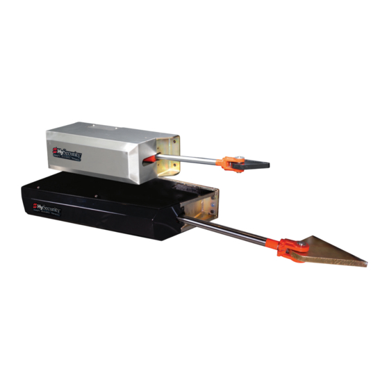
Page 86: Twin Hydraswings
ydra winGS A hydraulic splitter is used in twin HydraSwing models since only one HydraSupply controls two gates. Gate Close ports CAUTION Be aware hose swap is Gate Open needed on outswing gates. ports Conduit HydraSupply cabinet showing hose connections for Twin HydraSwing models MX3636-01 Rev. -
Page 87: Sequenced Gate: Configuration #1
equenced OnfiGuratiOn Vehicle Loop Layout HydraSwing with StrongArm M30 Optional access control devices (card reader, etc.). Align along 6 ft edge of the OUTSIDE Outside Obstruction Loop. OBSTRUCTION LOOP (OOLD) RESET LOOP (OOLD for Swing Gate) TRAFFIC CONTROL GATE Minimum spacing shown SECURITY SWING GATE... -
Page 88: Sequenced Gate: Configuration #2
equenced OnfiGuratiOn Vehicle Loop Layout HydraSwing with StrongArm M30 Optional access control devices (card reader, etc.). Align along 6 ft edge of the Outside Obstruction Loop. OUTSIDE OBSTRUCTION LOOP (OOLD) and Shadow Loop for Swing Gate SECURITY SWING GATE RESET LOOP (IOLD for Swing Gate) TRAFFIC CONTROL GATE *NOTICE... -
Page 89: Ehicle D Etector I Nstallation And L Oop L Ayouts
Vehicle Detector Installation and Loop Layouts HySecurity recommends that vehicle detectors be used for free exit and obstruction sensing logic only. The exception is in parking or barrier arm applications where detectors may also be used to close the gate. In applications employing our swing, vertical lift, or sliding gate operators, closing logic cannot be used except when the anti-tailgate logic is employed. -
Page 90: Vehicle Detectors And The Smart Touch Controller
NOTE: Standard box type 11 pin (24 VDC or 24 VAC) vehicle detectors may be connected in the traditional manner to the controller, but HySecurity Hy5B mini-detector modules plug directly into the board, making field installation much faster and enhancing performance. -
Page 91: Test The Vehicle Loop
Test the Vehicle Loop Run diagnostic tests on the vehicle loops before installing Hy5B vehicle detectors to ensure the loops are in good working condition. The following tests cannot guarantee a functioning loop, but failure of either test means that the loop may be damaged or need to be replaced. 1. -
Page 92: Install Hy5B Vehicle Detectors
DO NOT USE SENSOR 2 DO NOT USE STATUS SENSOR 3 the orientation of squared-off ends. DO NOT USE CHARGER AC LOSS HySecurity LOCK INTERLOCK MX000585 VERSION EMERG CLOSE FIRE DEPT OPEN Smart Touch Controller LIMIT DUAL GATE RADIO OPTIONS... - Page 93 You cannot combine Free Exit vehicle detection with reversing loop detection. If you attempt to do so, vehicles crossing over the Free Exit will not be detected. For more information, refer to the Hy5B User Guide and additional instructional material found online HySecurity website / Tech Support. Push terminals for Ground spade loop wire.
-
Page 94: Installing Standard 11-Pin Box Type Vehicle Detectors
SENSOR 2 Pin 2 DO NOT USE To LOOP terminal on Smart STATUS Touch Controller SENSOR 3 DO NOT USE CHARGER AC LOSS HySecurity LOCK INTERLOCK MX000585 VERSION EMERG CLOSE FIRE DEPT OPEN Smart Touch Controller LIMIT DUAL GATE RADIO OPTIONS NOTE: Both 24 Volts AC and DC are available, so either detector voltage may be used. -
Page 95: Loop Layouts: Single Lane, Bi- Or Single-Directional
ayOutS inGLe inGLe irectiOnaL For Openings less than 28 Feet Enter Exit OBSTRUCTION LOOP SWING GATE Two gate site scenarios include access control entry systems. • Bi-directional system with controlled access entry (card reader, radio control, etc.) and free exit gate is closed SHADOW by a “TIMER TO CLOSE.”... -
Page 96: Loop Layouts: Two Lane, Bi-Directional
ayOutS irectiOnaL For Openings greater than 28 Feet Enter Exit OBSTRUCTION LOOP OBSTRUCTION LOOP SWING GATE Two gate site scenarios include access control entry SHADOW systems. LOOP • Bi-directional system SHADOW with controlled access LOOP entry (card reader, radio control, etc.) and free Vehicles Uni-directional Single Lane exit gate is closed by a... -
Page 97: Photo Eye Installation
Photo Eye Installation A monitored connection tests for the presence and correct operation of the photo eyes (and other monitored sensors) prior to each gate activation. The monitored connection prevents gate operation if an entrapment protection sensor is missing or any fault is present. Sensors, such as gate edges and photoelectric beams, must be installed to protect against entrapment. -
Page 98: Photo Eyes (Non-Contact) Installation
Compatibility The UL 325 standard requires that a photoelectric sensor be laboratory tested and “recognized” under UL 325. In order to be compatible with all HySecurity operators, a photo eye must be rated to function from 24 VDC source power. -
Page 99: Configuration
HySecurity Sensors: Smart Touch on page 111. NOTE: HySecurity gate operators, manufactured with 2016 (or later) in the serial number, require Normally Closed output sensors. Some manufacturers label an output as N.O. (normally open), when it is actually an N.C. (normally closed) contact. Review External Entrapment Protection Sensors monitored by HySecurity Gate Operators on page iii. -
Page 100: Retro-Reflective Photo Eye Systems
etro eflective Hoto yStemS Correct installation and alignment of a retro-reflective photo eye and its reflector is important for trouble free performance. Any system operating at a range greater than 16 feet is more prone to false triggering due to dirty optics, condensation or poor weather. -
Page 101: Using Photo Eye Sensors Instead Of Vehicle Loops
UL 325 Standard of Safety for “monitored” VEHICLE DETECTOR external entrapment protection. To understand external SENSOR 1 entrapment protection and how HySecurity equipment monitors sensors, refer to the section titled Entrapment Photo Eye sensor terminal connections when Protection on page 29. -
Page 102: Photo Eye Alignment Feature
HOtO LiGnment eature Most photo eyes require careful optical alignment in order to aim the emitter beam to the center of the receiver or reflector. In order to avoid false triggering, it is important to carefully align the system. Align the photo eyes using this feature by taking the following steps: 1. -
Page 103: Installing Gate Edge Sensors
(photo eyes) sensors in your site plan. Sensors are wired to the Controller and require low voltage conduit to the operator and power supply. Refer to External Entrapment Protection Sensors monitored by HySecurity Gate Operators on page iii. To enable fully automatic operation, this gate operator requires a MINIMUM of one external entrapment protection sensor to monitor potential entrapment zones in either the open or close direction of travel. -
Page 104: Compatibility
The UL 325 Standard of Safety requires that a photoelectric sensor be laboratory tested and “recognized” under UL 325. In order to be compatible with all HySecurity gate operators, a photo eye must be rated to function from 24 VDC source power. -
Page 105: Troubleshooting
Refer to Table 8: Troubleshooting Codes on page 92 for details concerning identification and description of Alerts, Faults and Errors. Overriding a tripped sensor or fault condition on a HySecurity gate operator with monitored entrapment sensors requires a 2-step process: •... - Page 106 Type Alert/Fault/Error Display Buzzer Chirp Sequence Possible Cause & Suggested Corrective Action ALERT HYSECURITY 2 chirps per second every 2s An IES has been tripped twice within a specific period of time. Entrapment Mode while control input is active Check the gate site for obstructions and clear the gate area. To ENTR return to run mode operation, press the Reset button.
- Page 107 Type Alert/Fault/Error Display Buzzer Chirp Sequence Possible Cause & Suggested Corrective Action ALERT !ACTION BLOCKED 5 chirps indicating that the Operator received command to run open, but movement is GATE EDGE command cannot be initiated prevented. Gate edge blocked or disconnected and causes operator (Open or Close) to enter SAFE mode.
- Page 108 VFD is experiencing a fatal error. If you cannot clear the error alert by pressing the open or close button, contact HySecurity. ALERT ALERT 22 2 chirps per second every 3...
- Page 109 Check the wiring. Refer to the wiring diagram associated with the attached sensor. See Wiring HySecurity Sensors: Smart Touch on page 111. Be sure the eye “common” wire is wired properly to the SENSOR COM terminal.
- Page 110 Check wiring from the hydraulic cylinder to the STC. RPM SENSOR minute ERROR ERROR 9 3 chirps per second once per Only applies to DC Power Supply connection. Contact HySecurity. BATT DISCONNECT minute MX3636-01 Rev. D HydraSwing Programming & Operations © 2018...
-
Page 111: Access The Event Log Through The User Menu
Type Alert/Fault/Error Display Buzzer Chirp Sequence Possible Cause & Suggested Corrective Action ERROR ERROR 10 3 chirps per second once per VFD only. The operator tripped the fully Open or Close limit before SLOWDOWN SWITCH minute the Slowdown limit tripped. Check: Slowdown limit wiring and adjustment Adjustment of the limit ramps to verify that the limit switch is being tripped. -
Page 112: Electrical Issues
LectricaL SSueS A general set of troubleshooting procedures are provided in the following paragraphs. Use a voltmeter to take the measurements described in the steps. If at any point in the process, a result different than what’s expected occurs, stop and identify the problem. AC-Powered Gate Operators PROBLEM 1: Pushed the OPEN and CLOSE button, but the motor is not running. -
Page 113: Hydraswing Wiring Diagram: Pre-May 2017
HydraSwing Wiring Diagram: Pre-May 2017 For Reference Only. Refer to Wiring Diagram: HydraSwing/HydraSupply on page 16 if your gate operator was manufactured in May 2017 or later. It may contain a newer version of the VFD. VEHICLE DETECTOR VEHICLE DETECTOR VEHICLE DETECTOR VEHICLE DETECTOR STOP/BUZZER... -
Page 114: Mechanical Issues
NOTE: If the gate speed must be changed, contact your HySecurity distributor or HySecurity Tech Support. Extremely cold weather is unlikely to seriously affect the gate speed because HySecurity employs a special grade of hydraulic fluid (Uniflow), which maintains a linear viscosity over a broad temperature range. -
Page 115: Typical Problems And Troubleshooting Procedures
(e.g., a hex key) and blow on it to remove any debris. Contact HySecurity Technical Support first (see page 2) before performing this procedure. PROBLEM 3: The gate only opens or only closes. - Page 116 Gate speed in extremely cold weather Extremely cold weather is unlikely to seriously affect the speed of the gate, because HySecurity employs a special grade of hydraulic oil which maintains a very linear viscosity over a broad range of temperatures. Because of this high quality oil and other design considerations, we rate our operators for service in ambient temperatures of - 40°F to...
-
Page 117: General Maintenance
With S.T.A.R.T. software loaded on your laptop computer, you have an invaluable management tool for all HySecurity operators. The RS-232 serial port (found on the Smart Touch Controller), allows you to download system diagnostics and upload system configurations using the S.T.A.R.T. software. Instructions for downloading S.T.A.R.T. -
Page 118: Software Maintenance
The software on the STC board is periodically being enhanced with new features that create an easier install and improve the on-board diagnostic tools. Be sure to check the HySecurity website for the latest version of software and operator code before heading out for field maintenance. -
Page 119: Mechanical Maintenance
Fluid breakdown caused by heat is the main concern. If the unit is subjected to high use, or you are using the HySecurity biodegradable fluid option (especially in a warm climate), change the fluid more frequently. -
Page 120: Brake Valve Adjustments
To change the hydraulic fluid, 1. Position the gate so the cylinder is fully retracted. 2. Remove the reservoir from the pump pack. 3. Completely empty it. 4. Wipe the reservoir clean and clean the debris screen. 5. Re-assemble the pump unit and refill it with new Uniflow hydraulic fluid. 6. -
Page 121: Pressure Relief Valve Adjustments
Refer to Adjusting the Pressure Relief Valve on page 25 and follow the and solenoid instructions. For HySecurity Technical Support contact: 800-321-9947. Open Valve The open valve is solenoid operate`d and, when energized, directs the hydraulic flow to open the gate. No adjustment of this valve is possible or necessary. -
Page 122: Hydraswing Operator Maintenance Schedule
ydra winG peratOr aintenance cHeduLe Check at these recommended monthly intervals Name of part What to do Weekly Gate and hardware Check for damage and wear Anchor bolts & fasteners Check and tighten, if loose. If fasteners are worn, replace. Cylinder Apply grease to zerk fittings Large Hydraulic cylinder... -
Page 123: Hydrasupply Maintenance Schedule
ydra uppLy aintenance cHeduLe Check at these recommended monthly intervals Name of part What to do Weekly Inspect power unit Cycle test several times. Listen for unusual sounds or vibrations. Bolts & fasteners Check and tighten, if loose. If fasteners are worn, replace. - Page 124 Page intentionally left blank MX3636-01 Rev. D HydraSwing Programming & Operations © 2018...
-
Page 125: Wiring Hysecurity Sensors: Smart Touch
Wiring diagrams are provided on the following pages. The diagrams illustrate how to connect sensors and program the gate operator. HySecurity Smart Touch gate operators can monitor entrapment protection sensors per UL 325 - 2015 Standard of Safety using software version h4.50 (or later). -
Page 126: Wiring Tips For Sensor Com Terminal: Smart Touch
SenSOr cOm t irinG ipS fOr erminaL mart OucH Two SENSOR COM terminals exist (Terminal 14 and Terminal 15). If using multiple sensor devices, use a wire nut as a junction and pigtail to SENSOR COM. Or, install a separate terminal block and jumper outputs to one lead for either SENSOR COM terminal. -
Page 127: Smart Touch: 2 Ch Wired Edge With Hy2Nc
FLASHING GREEN LOCK INTERLOCK MX000585 EDGE 2 Actively Monitoring VERSION EMERG CLOSE FIRE DEPT OPEN Smart Touch Controller LIMIT DUAL GATE RADIO OPTIONS Channel wires to 10k Edges OPEN +24V +24V © 2018 Wiring HySecurity Sensors: Smart Touch MX3636-01 Rev. D... -
Page 128: Smart Touch: Wired Edge Sensor With Gem (-104)
Green output wire can attach DO NOT USE to any SENSOR input. CHARGER AC LOSS HySecurity *NOTE: Make sure whichever wired input used (SENSOR 1, 2, or 3) is the LOCK INTERLOCK MX000585 same Sensor # configured through the Installer Menu. -
Page 129: Smart Touch: Photo Eye Thru Beam (Emx Irb Mon)
DIP switches must be set as shown otherwise the photo eye will not operate correctly. If you receive an Alert, "!ACTION BLOCKED" "Photo Eye Open" PEO or "Photo Eye Close" PEC, take steps to align the photo eye. Refer to Photo Eye Alignment Feature on page 88. © 2018 Wiring HySecurity Sensors: Smart Touch MX3636-01 Rev. D... -
Page 130: Smart Touch: Photo Eye / Reflective (E3K R10K4)
CHARGER CAUTION AC LOSS HySecurity LOCK INTERLOCK MX000585 Do NOT connect the 10K VERSION resistor to HySecurity EMERG CLOSE gate operators. Follow the FIRE DEPT OPEN instructions on this sheet to avoid FAULT 2. Smart Touch Controller LIMIT DUAL GATE... -
Page 131: Smart Touch: The Solution, Mim-62 (Multi-Input Module)
All external entrapment protection sensors must be NC sensor outputs and wired to the SENSOR COM terminal for monitoring and powering purposes. The sensor becomes actively powered when the gate operator's motor runs. © 2018 Wiring HySecurity Sensors: Smart Touch MX3636-01 Rev. D... -
Page 132: Smart Touch: Photo Eye / Reflecti-Guard (Rg-R)
4, jumper, PWR Relay to DO NOT USE CM terminal SENSOR 2 DO NOT USE STATUS SENSOR 3 DO NOT USE CHARGER AC LOSS HySecurity LOCK INTERLOCK MX000585 VERSION EMERG CLOSE FIRE DEPT OPEN Smart Touch Controller RADIO OPTIONS LIMIT DUAL GATE... -
Page 133: Smart Touch: Wireless Edge, Wireless Gate Link
Test button on the Transmitter Wireless Edge Link (Receiver) MGL - RX20 to complete the LEARN mode Signal received from battery- process and sync the receiver and powered Transmitter (MGL - TX20) transmitter. © 2018 Wiring HySecurity Sensors: Smart Touch MX3636-01 Rev. D... -
Page 134: Smart Touch: Wired Edge With Gem-104 & Photo Eye
DO NOT USE 3 = OFF STATUS 4 = ON SENSOR 3 DO NOT USE CHARGER AC LOSS HySecurity NOTE: DIP switches must LOCK INTERLOCK MX000585 be set as shown otherwise VERSION EMERG CLOSE the photo eye will not operate correctly. -
Page 135: Smart Touch: Wireless Edge Gate Link & Photo Eye
Use receivers & transmitters Version 1.02 or later. OUTPUT DIP switches for CH1 and CH2. Verify dip switch is set to “R” for each channel used. HySecurity uses NC SELECT "Relay" sensors. Do NOT select "P" as the output. P = "Pulse" device. - Page 136 MX3636-01 Rev. D HydraSwing Programming & Operations © 2018...
-
Page 137: Warranty
3. Buyer’s Exclusive Remedies for Any Nonconformity. 500,000 gate cycles (whichever occurs first), after the date of installation, If a HySecurity product fails to conform to the warranties in Section 1, Buyer must e. Electromechanical Barrier Arm Operators: Two years or 1,000,000 gate cycles... -
Page 138: Specifications
Inc. Federal copyright law prohibits the reproduction, distribution, or public display of copyrighted materials without the express written permission of the copyright owner, unless fair use or other exemption under copyright law applies. Additionally, HySecurity Gate, Inc. makes no representations or warranty with respect to this manual. We also reserve the right to make changes in the products described without notice and without any obligation to notify any persons of any such revision or change.
Need help?
Do you have a question about the HydraSwing 40 Twin and is the answer not in the manual?
Questions and answers