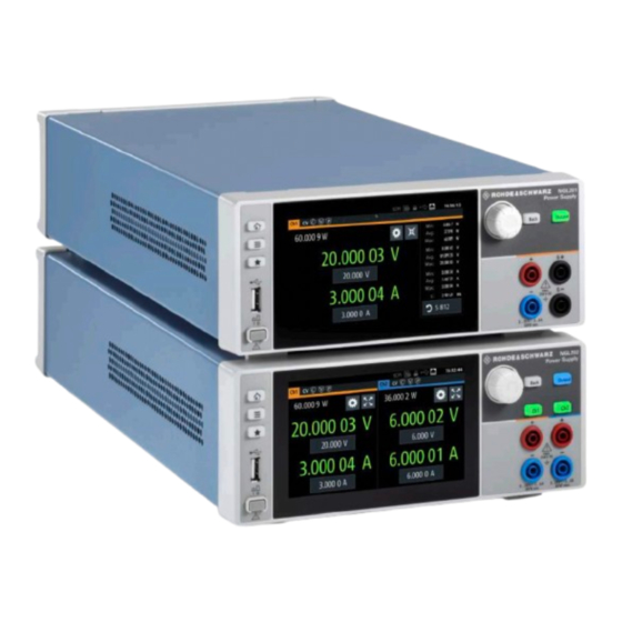
R&S NGL200 Series User Manual
Hide thumbs Also See for NGL200 Series:
Table of Contents

Advertisement

®
R&S
Power Supply Series
User Manual
(;ÜåT2)
1178873602
Distributed by:
Sie haben Fragen oder wünschen eine Beratung? Angebotsanfrage unter 07121 / 51 50 50 oder über info@datatec.de
NGL200/NGM200

Advertisement

Table of Contents
loading

Summary of Contents for R&S NGL200 Series

  • Page 1 ® R&S NGL200/NGM200 Power Supply Series User Manual (;ÜåT2) 1178873602 Distributed by: Sie haben Fragen oder wünschen eine Beratung? Angebotsanfrage unter 07121 / 51 50 50 oder über info@datatec.de...
  • Page 2 ® This manual describes the following R&S NGL/NGM models with firmware version 1.00 or higher: ● ® R&S NGL201 Single-channel power supply 60W (3638.3376.02) ● ® R&S NGL202 Two-channel power supply 120W (3638.3376.03) ● ® R&S NGM201 Single-channel power supply 60W (3638.4472.02) ●...
  • Page 3 Safety Instructions Instrucciones de seguridad Sicherheitshinweise Consignes de sécurité Risk of injury and instrument damage The instrument must be used in an appropriate manner to prevent electric shock, fire, personal injury or instrument damage. Do not open the instrument casing. ●...
  • Page 4 Gefahr von Verletzungen und Schäden am Gerät Betreiben Sie das Gerät immer ordnungsgemäß, um elektrischen Schlag, Brand, Verletzungen von Personen oder Geräteschäden zu verhindern. Öffnen Sie das Gerätegehäuse nicht. ● Lesen und beachten Sie die "Grundlegenden Sicherheitshinweise", ● die als gedruckte Broschüre dem Gerät beiliegen. Lesen und beachten Sie die Sicherheitshinweise in den folgenden ●...
  • Page 5 Customer Support Technical support – where and when you need it For quick, expert help with any Rohde & Schwarz equipment, contact one of our Customer Support Centers. A team of highly qualified engineers provides telephone support and will work with you to find a solution to your query on any aspect of the operation, programming or applications of Rohde &...
  • Page 6: Table Of Contents

    ® Contents R&S NGL200/NGM200 Contents 1 Documentation Overview..............7 2 Welcome to R&S NGL/NGM..............9 3 Important Notes..................10 Symbols........................10 Ambient Conditions....................10 Measurement Categories....................11 Mains Voltage.......................11 Limits..........................12 4 Getting Started..................13 Putting into Operation....................13 4.1.1 Safety..........................14 4.1.2 Intended Operation.......................
  • Page 7 ® Contents R&S NGL200/NGM200 5.2.1 Using Gestures......................30 5.2.2 Accessing Functionality in the Home Window.............. 30 5.2.2.1 Settings Button......................31 5.2.2.2 Voltage and Current Inputs................... 31 5.2.2.3 Expand/Collapse Button....................32 5.2.3 Input Data........................33 Front Panel Keys......................34 5.3.1 Menu Controls.......................34 5.3.1.1 Home Key........................34 5.3.1.2 Settings Key........................
  • Page 8 ® Contents R&S NGL200/NGM200 User Key........................67 Screenshot........................68 6.10 Data Logging....................... 69 6.11 FastLog........................71 6.12 CSV Settings........................72 6.13 File Manager........................ 73 6.14 Store and Recall ......................74 6.15 Interfaces........................76 6.15.1 Network Connection......................77 6.15.1.1 LAN Connection......................78 6.15.1.2 Wireless LAN Connection..................... 80 6.15.2 USB Connection......................81 6.15.3...
  • Page 9 ® Contents R&S NGL200/NGM200 7.5.7 Output Setting......................111 7.5.8 Range/DVM Setting.....................117 7.5.9 OCP Setting.........................118 7.5.10 OVP Setting........................ 122 7.5.11 OPP Setting........................ 125 Measurement Commands..................128 Advanced Operating Commands................131 7.7.1 Arbitrary........................131 7.7.2 Ramp...........................136 7.7.3 Digital I/O........................137 7.7.4 Battery Simulation....................... 139 Data and File Management Commands..............
  • Page 10: Documentation Overview

    ® Documentation Overview R&S NGL200/NGM200 1 Documentation Overview This section provides an overview of the R&S NGL/NGM user documentation. You can find it on the product page at: www.rohde-schwarz.com/product/ngl200 www.rohde-schwarz.com/product/ngm200 Getting Started Introduces the R&S NGL/NGM power supply series and describes how to set up and start working with the instrument.
  • Page 11 ® Documentation Overview R&S NGL200/NGM200 See www.rohde-schwarz.com/firmware/ngl200. The open source acknowledgment document can also be read directly on the instrument. See www.rohde-schwarz.com/firmware/ngm200. The open source acknowledgment document can also be read directly on the instrument. User Manual 1178.8736.02 ─ 05...
  • Page 12: Welcome To R&S Ngl/Ngm

    ® Welcome to R&S NGL/NGM R&S NGL200/NGM200 2 Welcome to R&S NGL/NGM The one or two-channel power supply series are based on a classical transformer con- cept with linear regulators. This concept allows the instrument to achieve highest accu- racy and lowest residual ripple. The R&S NGL/NGM power supply series feature galvanically isolated, floating over- load and short-circuit proof outputs.
  • Page 13: Important Notes

    ® Important Notes R&S NGL200/NGM200 Ambient Conditions 3 Important Notes 3.1 Symbols Caution, general danger zone Ground PE terminal ON (supply voltage) OFF (supply voltage) Ground terminal 3.2 Ambient Conditions The allowed operating temperature ranges from +5 °C to +40 °C (pollution category 2). The maximum relative humidity (without condensation) is at 80 %.
  • Page 14: Measurement Categories

    ® Important Notes R&S NGL200/NGM200 Mains Voltage ~72 °C, a channel-specific overheat protection intervenes. Affected outputs will auto- matically be switched off. Air circulation Do not obstruct the ventilation holes! 3.3 Measurement Categories This instrument is designed for supplying power on circuits that are only indirectly con- nected to the low voltage mains or not connected at all.
  • Page 15: Limits

    ® Important Notes R&S NGL200/NGM200 Limits against the spring pressure until it locks into place. The use of mended fuses or short circuiting the fuse holder is prohibited. Resulting damages are not covered by the war- ranty. Safe operation If the instrument is not in use, it must be switched off at the mains switch for safety rea- sons.
  • Page 16: Getting Started

    ® Getting Started R&S NGL200/NGM200 Putting into Operation 4 Getting Started 4.1 Putting into Operation This chapter describes how to set up the R&S NGL/NGM power supply series for the first time. Risk of injury and instrument damage The instrument must be used in an appropriate manner to prevent electric shock, fire, personal injury, or damage.
  • Page 17: Safety

    ® Getting Started R&S NGL200/NGM200 Putting into Operation EMI impact on measurement results Electromagnetic interference (EMI) may affect the measurement results. To suppress the generated EMI: ● Use suitable shielded cables of high quality, for example, LAN cables ● Note the EMC classification in the data sheet 4.1.1 Safety This instrument was built in compliance with DIN EN 61010-1, safety regulations for electrical instruments, control units and Iaboratory equipment.
  • Page 18: Intended Operation

    ® Getting Started R&S NGL200/NGM200 Putting into Operation Exceeding the low voltage protection Use insulated wires and not bare wires for the terminal connection. It is assumed that only qualified and trained personnel service the power supplies and the connected loads. Before switching on the product, it must be ensured that the nominal voltage setting on the product matches the nominal voltage of the AC supply network.
  • Page 19: Unpacking And Checking The Instrument

    ® Getting Started R&S NGL200/NGM200 Putting into Operation Table 4-1: General data on instrument specification General data Mains nominal voltage AC 100 V / 115 V / 230 V (±10 %) 50 Hz to 60 Hz Maximum power consumption 400 W Mains fuses 2 x IEC T4.0H 250 V +5 °C to +40 °C...
  • Page 20: Setting Up The Instrument

    ® Getting Started R&S NGL200/NGM200 Putting into Operation Risk of damage during transportation and shipment Insufficient protection against mechanical and electrostatic effects during transportation and shipment can damage the instrument. ● Always ensure that sufficient mechanical and electrostatic protections are provided ●...
  • Page 21: Rack Mounting

    ® Getting Started R&S NGL200/NGM200 Instrument Tour Positioning of instrument The instrument must be positioned in a manner that allows you to disconnect the unit from the mains at any time and without restrictions. 4.1.4.2 Rack Mounting The instrument can be installed in a 19" rack using the rack adapter R&S HZN96 (P/N 3638.7813.02).
  • Page 22 ® Getting Started R&S NGL200/NGM200 Instrument Tour Figure 4-2: Front panel of R&S NGL/NGM with 2 channels 1 = Display with touch screen 2 = Menu control keys 3 = Rotary knob and back key 4 = Output and channel keys 5 = Output terminals (one channel with sense for NGL201, NGM201;...
  • Page 23: Rear Panel

    ® Getting Started R&S NGL200/NGM200 Instrument Tour Output and channel keys (4) The channel key allows you to select the power supply channel to source or sink power. The output key allows you to enable or disable the output power on the channel key.
  • Page 24 ® Getting Started R&S NGL200/NGM200 Instrument Tour 13 = Ethernet (LAN) connector 14 = Optional IEEE-488 (GPIB) interface 15 = Digital I/O connector AC inlet with fuse holder and voltage selector (8) Main supply cord Do not use detachable mains supply cord with inadequate rating. The power cable must be plugged in before signal circuits can be connected.
  • Page 25: Switching On The Instrument

    ® Getting Started R&S NGL200/NGM200 Instrument Tour Option IEEE-488 (GPIB) interface (14) An IEEE-488 (GPIB) interface can be ordered (NGL-B105 or NGM-B105). This inter- face is not user installable. Digital I/O connector (15) The Digital I/O option (R&S NGL-K103 or R&S NGM-K103) must be installed for this function to be available in the instrument.
  • Page 26: Trying Out The Instrument

    ® Getting Started R&S NGL200/NGM200 Trying Out the Instrument Fuse rating The R&S NGL/NGM uses the same fuse ratings for all mains voltages. To change power fuse: 1. Peel off the yellow label sticker on the AC inlet. 2. Release the latch of the fuse holder which is located at both side of the socket and pull it out.
  • Page 27: Setting The Output Voltage And Current

    ® Getting Started R&S NGL200/NGM200 Trying Out the Instrument Source and sink current The R&S NGL/NGM power supply series are 2 quadrant power supplies which may both source and sink current. When the voltage across the output terminal exceeds the set voltage, current flows into the instrument.
  • Page 28: Maintenance

    ® Getting Started R&S NGL200/NGM200 Maintenance Color illuminated on front panel keys and display Operating mode font color of voltage and current in home window Constant voltage mode (CV) Green Constant current mode (CC) Constant resistance mode (CR) Note: Instrument is operated in sink mode and Cyan "Constant Resistance"...
  • Page 29: Operating Basics

    ® Operating Basics R&S NGL200/NGM200 Display Overview 5 Operating Basics 5.1 Display Overview The following displays the home window of R&S NGL/NGM. It shows the output volt- age and current level, status bar information and control settings of the instrument. Figure 5-1: Home window of R&S NGL/NGM with 2 channels 1 = Device status bar 2 = Channel status bar...
  • Page 30 ® Operating Basics R&S NGL200/NGM200 Display Overview Device status bar Function Description If touch input is disabled, the icon is displayed and Touchscreen highlighted in yellow. Chapter 5.3.1.3, "User Key", on page 37. If a SCPI command is received successfully, the SCPI command icon blinks once in white.
  • Page 31 ® Operating Basics R&S NGL200/NGM200 Display Overview Channel status bar Function Description Channel number Channel number indication. Operation mode The R&S NGL/NGM has three operating modes: ● CV: Constant voltage mode ● CC: Constant current mode ● CR: Constant resistance mode. The R&S NGL/NGM goes into this mode when operates in sink mode and the "Constant Resistance"...
  • Page 32: Channel Display Area

    ® Operating Basics R&S NGL200/NGM200 Display Overview Function Description If enabled, the icon is highlighted in white. "Output Delay" The delay is the time between activation of the out- put and applying voltage to the output. Chapter 6.2.3, "Output", on page 44. If sense connection is detected, the icon is highligh- Sense connection ted in white.
  • Page 33: Using The Touchscreen

    ® Operating Basics R&S NGL200/NGM200 Using the Touchscreen Figure 5-3: Color coding of operating conditions Color Operating mode Description DVM mode Display DVM measurement. Editing mode A solid blue cursor is shown when an item is selected. CV mode Active outputs are operated in a constant voltage mode. CC mode Active outputs are operated in a constant current mode.
  • Page 34: Settings Button

    ® Operating Basics R&S NGL200/NGM200 Using the Touchscreen 5.2.2.1 Settings Button The "Settings" button navigates to the device/channel menu window where you can set device or individual channel settings on the instrument. 1. Select the "Settings" button. The R&S NGL/NGM displays device/channel menu window. 2.
  • Page 35: Expand/Collapse Button

    ® Operating Basics R&S NGL200/NGM200 Using the Touchscreen 1. Select the voltage or current field in the channel display area to set value. The R&S NGL/NGM displays the on-screen keypad to enter value. 2. Set the required value. Chapter 5.2.3, "Input Data", on page 33.
  • Page 36: Input Data

    ® Operating Basics R&S NGL200/NGM200 Using the Touchscreen 1 = Minimum, maximum and average value for power, voltage and current 2 = Calculation of energy result 3 = Number of samples collected 4 = Channel display area of selected channel 5 = Digital I/O trigger of selected channel 5.2.3 Input Data The R&S NGL/NGM provides an on-screen keypad for you to enter numerical values.
  • Page 37: Front Panel Keys

    ® Operating Basics R&S NGL200/NGM200 Front Panel Keys Figure 5-8: Alphanumeric input data 5.3 Front Panel Keys For an overview of the front panel keys, see Figure 4-2. 5.3.1 Menu Controls The menu controls keys provide navigation on the available menus in the instrument. 5.3.1.1 Home Key The [Home] key navigates to the instrument home window.
  • Page 38 ® Operating Basics R&S NGL200/NGM200 Front Panel Keys Alternatively, press [Settings] key. 3. Select the "Device" tab to access the device menu. Figure 5-9: Device menu Menu Description "Arb Editor" Programs the waveform of voltage and current settings for the channel output.
  • Page 39 ® Operating Basics R&S NGL200/NGM200 Front Panel Keys Menu Description "Data & Time" Configures date, time and clock format of the instrument. "Appearance" Configures brightness level for screen display and frontpanel keys. "Sound" Enables/Disables sound when selected trigger events occur. "Licenses"...
  • Page 40: User Key

    ® Operating Basics R&S NGL200/NGM200 Front Panel Keys Menus Description "Battery Simulator" Available only with option R&S NGM-K106. Activation of the "Battery Simulator" function and edit new bat- tery model data. Configures OCP protection settings ("Blowing Delay", "Initial Delay" and linking channel) for the instrument. Configures OVP protection settings (OVP level) for the instru- ment.
  • Page 41: Output And Channel Controls

    ® Operating Basics R&S NGL200/NGM200 Operation Modes [Back] key Using the [Back] key, you can do several things: ● Navigate to the previous menu window ● Close or discard changes made on the on-screen keypad ● Close the instrument pop-up messages 5.3.3 Output and Channel Controls Applicable only for 2-channel models (NGL202, NGM202), these keys control the channel output settings of the instrument.
  • Page 42 ® Operating Basics R&S NGL200/NGM200 Operation Modes between CV and CC depending on the connected load. When CR is configured, the instrument is not switched to CR mode automatically, it will operate in CR mode when sinking but source in CV or CC mode. CV mode Figure 5-12 shows that if the instrument is in the range of voltage regulation, the output...
  • Page 43: Instrument Functions

    ® Instrument Functions R&S NGL200/NGM200 Setting the Channels Voltage and Current 6 Instrument Functions 6.1 Setting the Channels Voltage and Current The R&S NGL/NGM comes with the following instrument models: Models Channels NGL201, NGM201 NGL202, NGM202 Ch1, Ch2 Toggle the respective channel key ([Ch1], [Ch2] ) on the front panel to select these channels.
  • Page 44: Activating The Channels Output

    ® Instrument Functions R&S NGL200/NGM200 Activating the Channels Output Figure 6-2: Voltage and current settings in the instrument 6.2 Activating the Channels Output The outputs of all the channels (Ch1, Ch2) can be switched on or off by toggling the [Output] key on the front panel.
  • Page 45: Set Constant Resistance

    ® Instrument Functions R&S NGL200/NGM200 Activating the Channels Output Figure 6-3: Output of Ch2 in CV mode 6.2.1 Set Constant Resistance By enabling the constant resistance (CR) mode, you can operate the R&S NGL/NGM as an electronic load in sink mode. This allows you to perform testing that requires a constant load resistor in your application.
  • Page 46: Fast Transient Response

    ® Instrument Functions R&S NGL200/NGM200 Activating the Channels Output Figure 6-4: Constant resistance dialog 6.2.2 Fast Transient Response With fast transient response, the R&S NGL/NGM is able to quickly stabilize the output voltage upon a step change in the load current. Load transient recovery time can be switched between 30 μs ("Fast Transient Response"...
  • Page 47: Output

    ® Instrument Functions R&S NGL200/NGM200 Activating the Channels Output 3. Activate the "Fast Transient Response" from the menu. The R&S NGL/NGM applies the fast transient response on the operating condition and displays the "Fast Transient Response" icon on the selected channel status bar information.
  • Page 48 ® Instrument Functions R&S NGL200/NGM200 Activating the Channels Output 1. Select the "Impedance" menu item to configure the required values. The R&S NGL/NGM displays the "Output Impedance" dialog. 2. Set the required value. The R&S NGL/NGM displays the onscreen keypad for entry. 3.
  • Page 49 ® Instrument Functions R&S NGL200/NGM200 Activating the Channels Output 3. Select the required trigger action. ● Output On: If triggered, the selected output channel is turned on. ● Output Off: If triggered, the selected output channel is turned off. ● Gated: If triggered, the selected output channel is gated.
  • Page 50 ® Instrument Functions R&S NGL200/NGM200 Activating the Channels Output Output delay The output delay is the time between the "Output On" event and the available voltage at the output terminals. See Figure 6-7. Figure 6-7: Output delay at the output terminals When the instrument output delay is activated, the front panel of the respective chan- nel key (i.e [Ch1], [Ch2]) blinks in green and a "DELAY"...
  • Page 51: Ranges / Digital Voltmeter (Dvm)

    ® Instrument Functions R&S NGL200/NGM200 Ranges / Digital Voltmeter (DVM) 6.3 Ranges / Digital Voltmeter (DVM) Instrument option R&S NGM-K104 (P/N: 3643.9927.02) option is required for Digital Voltmeter measure- ments. Ranges / Digital Voltmeter (DVM) is only available on NGM devices. Equipped with option R&S NGM-K104, the R&S NGM provides an independent digital voltmeter (DVM) to measure input voltage.
  • Page 52 ® Instrument Functions R&S NGL200/NGM200 Ranges / Digital Voltmeter (DVM) Figure 6-10: Range/DVM dialog Note: The "Voltage Autorange" and "Voltage Range" are not available if DVM is enabled. 4. Activate the "Enable DVM Measurement" menu item. The R&S NGL/NGM enables the DVM measurement and displays a DVM text in the channel display area.
  • Page 53: Battery Simulator

    ® Instrument Functions R&S NGL200/NGM200 Battery Simulator 100 mA Accuracy from 0 A to 100 mA. 10 mA Accuracy from 0 A to 10 mA. 6.4 Battery Simulator Instrument option R&S NGM-K106 (P/N: 3636.6626.02) option is required. Battery Simulator is only available on NGM devices. Equipped with battery simulator option, the R&S NGM can be used as a battery source in developing products whereby battery is not ready for testing, such as phones and portable devices.
  • Page 54 ® Instrument Functions R&S NGL200/NGM200 Battery Simulator Table 6-2: Battery simulator parameters Battery simulator parameters Descriptions State of charge represents the current battery capacity, e.g. 85% SoC represents that 15% of bat- tery capacity is used. Voc is the voltage between the battery terminals with no load applied.
  • Page 55 ® Instrument Functions R&S NGL200/NGM200 Battery Simulator Figure 6-12: Battery simulator dialog 4. Activates the "Enabled" menu item. The R&S NGM enables the battery simulation function. 5. Select the "Load frrom file..." to load the battery model file. The R&S NGM opens a dialog to select the source and file location. 6.
  • Page 56 ® Instrument Functions R&S NGL200/NGM200 Battery Simulator 4. Select "Edit existing file" to edit an existing battery model file. The R&S NGM opens a dialog to select the source and file to edit existing file. 5. Select the required source and file for editing. 6.
  • Page 57 ® Instrument Functions R&S NGL200/NGM200 Battery Simulator Figure 6-13: Battery model editor dialog 7. Configure the "Battery Model Editor" with the required state of charge (SoC), open- circuit voltage (Voc) and internal resistance (ESR). The R&S NGM displays the on-screen keypad for data entry. See also Table 6-2.
  • Page 58: Protection

    ® Instrument Functions R&S NGL200/NGM200 Protection 6.5 Protection There are various ways in which the R&S NGL/NGM protects itself and the connected load from damage due to overvoltage, overcurrent and overpower drawn by the load during testing. 1. Press [Settings] key. The R&S NGL/NGM displays the device/channel menu window.
  • Page 59: Over Voltage Protection (Ovp)

    ® Instrument Functions R&S NGL200/NGM200 Protection 5. Activate the "Link to Channel 2" or "Link to Channel 1" menu item. ● ON: The linked channel is turned off when an OCP event is triggered. ● OFF: The linked channel is not affected when an OCP event is triggered. 6.5.2 Over Voltage Protection (OVP) When the output voltage exceeds the limit set for the respective channel, an alert is triggered and the affected channel is turned off according to the settings configured in...
  • Page 60: Safety Limits

    ® Instrument Functions R&S NGL200/NGM200 Protection Figure 6-16: Over power protection dialog 2. Activate the "Enabled" menu item. The R&S NGL/NGM enables the OPP and displays the "Over Power Protection (OPP)" icon on the selected channel status bar information. 3. Set the required level for OPP. The R&S NGL/NGM displays the on-screen keypad to set the value.
  • Page 61: Trigger / Digital I/O

    ® Instrument Functions R&S NGL200/NGM200 Trigger / Digital I/O 2. Activate the "Enabled" menu item. The R&S NGL/NGM limits the set voltage and current level and displays the "Safety Limits" icon on the selected channel status bar information. 3. Set the required minimum and maximum value for voltage and current level. The R&S NGL/NGM displays an on-screen keypad to set the value.
  • Page 62 ® Instrument Functions R&S NGL200/NGM200 Trigger / Digital I/O Figure 6-18: Overview of trigger IO system Table 6-3: Trigger-in signals Trigger-in parameters Source Descriptions Ext trigger Ch1 Digital In, pin 2 of Digi- If detected, corresponding trigger-out parameters tal I/O connector are triggered.
  • Page 63 ® Instrument Functions R&S NGL200/NGM200 Trigger / Digital I/O Trigger-in parameters Source Descriptions CC, CV, CR, Protection, Sink Operation Mode If respective channel operation modes, protection event or sink mode is detected, corresponding trigger-out parameters are triggered. Figure 6-18. User button User button If detected, corresponding trigger-out parameters are triggered.
  • Page 64 ® Instrument Functions R&S NGL200/NGM200 Trigger / Digital I/O Figure 6-19: Digital output fault signal Digital I/O connector The Digital I/O connector is located below the GPIB connector, see Chapter 4.2.1.2, "Rear Panel", on page 20. Figure 4-4 Table 4-2 for the Digital I/O connector and pins layout.
  • Page 65 ® Instrument Functions R&S NGL200/NGM200 Trigger / Digital I/O 6. Select "Digital Output" to configure the trigger-out parameter. The R&S NGL/NGM displays the "Digital Output" dialog. Figure 6-21: Digital Out dialog 7. Depending on your requirements, select the digital output accordingly. The two Digital I/O output pins OUT1 and OUT2 can be set directly by the SCPI commands.
  • Page 66: Advanced Features

    ® Instrument Functions R&S NGL200/NGM200 Advanced Features The R&S NGL/NGM starts or steps through the arbitrary signal when a trigger is detected. 6.7 Advanced Features The "Arbitrary" and "Ramp" are two functions which can be used to control the wave- form of voltage and current output.
  • Page 67: Arbitrary Editor

    ® Instrument Functions R&S NGL200/NGM200 Advanced Features 7. Select "Load" to load the selected file. The R&S NGL/NGM loads the selected arbitrary file. 8. Applicable only with R&S NGL-K103 or R&S NGM-K103, Digital Output option. Chapter 6.6, "Trigger / Digital I/O", on page 58.
  • Page 68 ® Instrument Functions R&S NGL200/NGM200 Advanced Features 4. Select "Edit existing file" to edit an existing arbitrary file. The R&S NGL/NGM opens a dialog to select the source and file to edit existing file. 5. Select the required source and file for editing. 6.
  • Page 69: Ramp

    ® Instrument Functions R&S NGL200/NGM200 Advanced Features 11. Set the "Rep" to configure repetition cycle for the arbitrary data. By default, the repetition cycle is set to infinity. 12. Set the "End Behavior" to handle the way to end the automation of the arbitrary function.
  • Page 70: User Key

    ® Instrument Functions R&S NGL200/NGM200 User Key The R&S NGL/NGM displays the "Ramp" dialog. Figure 6-25: Ramp dialog 4. Activate the "Enabled" menu item. The R&S NGL/NGM enables the ramping function and displays the "Ramp" icon on the selected channel status bar information. 5.
  • Page 71: Screenshot

    ® Instrument Functions R&S NGL200/NGM200 Screenshot Figure 6-26: User button action 4. Select the "User Button Action" to configure the user action. The R&S NGL/NGM displays a dialog to configure the user action. 5. Select the required user action. ● "Screenshot": Capture the current screen image of the instrument ●...
  • Page 72: Data Logging

    ® Instrument Functions R&S NGL200/NGM200 Data Logging Figure 6-27: Screenshot dialog 4. Select the "Save Location" to configure the screenshot file location. ● "Auto": Target folder is set to default file location: /USB1A/NGL202/screenshot for NGL models /USB1A/NGM202/screenshot for NGM models ●...
  • Page 73 ® Instrument Functions R&S NGL200/NGM200 Data Logging 3. Select "Logging" menu item from the menu. The R&S NGL/NGM displays the "Logging" dialog. 4. Select the "Save Location" menu item to select the predefined target folder for data logger. ● "Auto": "Target Folder" is auto-selected. If no USB stick is detected, "Target Folder"...
  • Page 74: Fastlog

    ® Instrument Functions R&S NGL200/NGM200 FastLog 8. Applicable only with R&S NGL-K103, activate the "Triggered" menu item if data logging is required under triggered conditions. If activated, the R&S NGL/NGM executes the data logging if a trigger event occurs. Figure 6-18 Figure 6-26.
  • Page 75: Csv Settings

    ® Instrument Functions R&S NGL200/NGM200 CSV Settings 4. Select "Enabled" to activate the "FastLog" function. The R&S NGM starts the fast logging and displays the "Fast Logging" icon at the device status bar information. 5. Select "Triggered" to "ON" if you want "FastLog" to be enabled by a trigger event. 6.
  • Page 76: File Manager

    ® Instrument Functions R&S NGL200/NGM200 File Manager Figure 6-30: CSV settings dialog 2. Set the required CSV parameters. The R&S NGL/NGM displays the respective dialog to set the CSV parameters. Table 6-5. 3. Select "Set" to confirm the value. Table 6-5: CSV settings CSV Settings Selective fields in the dialog Field Delimiter...
  • Page 77: Store And Recall

    ® Instrument Functions R&S NGL200/NGM200 Store and Recall Figure 6-31: File manager dialog 4. Select the file that you want to copy or delete. 5. Select the required action in the file manager dialog. Table 6-6. Table 6-6: File manager action Action Description Copy from internal memory to USB.
  • Page 78 ® Instrument Functions R&S NGL200/NGM200 Store and Recall ● Settings in the Protection Function, Safety Limits ● Arbitrary settings, Ramp settings ● User button key function ● Data Logging settings ● GPIB Address 1. Press [Settings] key. The R&S NGL/NGM displays the device/channel menu window. 2.
  • Page 79: Interfaces

    ® Instrument Functions R&S NGL200/NGM200 Interfaces 2. Select "Yes" to overwrite instrument settings to factory default. The R&S NGL/NGM reset current instrument settings to factory default. 3. The R&S NGL/NGM displays a popup message to show that all settings are reset to factory default.
  • Page 80: Network Connection

    ® Instrument Functions R&S NGL200/NGM200 Interfaces Figure 6-33: Interfaces dialog 4. Select the connected interface (Network, USB Class GPIB Address) to configure the necessary parameters required. ● Network Connection....................77 ● Connection......................81 ● GPIB Address......................82 6.15.1 Network Connection There are two methods to establish a local area network (LAN) connection with the R&S NGL/NGM for remote control operation.
  • Page 81: Lan Connection

    ® Instrument Functions R&S NGL200/NGM200 Interfaces The R&S NGL/NGM displays the on-screen keypad to enter the port number and hostname. ● "SCPI Raw Port": A port number used to open a raw TCP/IP connection to send raw SCPI commands to the instrument ●...
  • Page 82 ® Instrument Functions R&S NGL200/NGM200 Interfaces 1. Connect the LAN cable to the LAN connector at the rear panel of the instrument. 2. Select "LAN" to set LAN connection. The R&S NGL/NGM displays the "Ethernet Settings" dialog. Note: The "MAC Address" is fixed. Figure 6-35: Ethernet settings dialog 3.
  • Page 83: Wireless Lan Connection

    ® Instrument Functions R&S NGL200/NGM200 Interfaces 7. Select "Set" to confirm the value. 8. Select "Apply Configuration" to apply the changes. 6.15.1.2 Wireless LAN Connection Risk of RF exposure When WLAN is active, a minimum separation distance of 20 cm from front panel of the instrument must be observed at all times.
  • Page 84: Usb Connection

    ® Instrument Functions R&S NGL200/NGM200 Interfaces 2. Select "Enable" menu item to set "On" to enable wireless LAN. The R&S NGL/NGM began searching available WiFi network and the "Status" shows "Searching". 3. Select the "Select Network" to connect the required WiFi network. If connection is successful, the "Status"...
  • Page 85: Gpib Address

    ® Instrument Functions R&S NGL200/NGM200 Interfaces 6.15.3 GPIB Address Instrument option R&S NGL-B105 (P/N: 3652.6356.02) or R&S NGM-B105 (P/N: 3641.6220.02) option needs to be installed for the remote command of R&S NGL/NGM via GPIB interface. The GPIB interface, sometimes called the General Purpose Interface Bus (GPIB), is a general purpose digital interface system that can be used to transfer data between two or more devices.
  • Page 86: General Instrument Settings

    ® Instrument Functions R&S NGL200/NGM200 General Instrument Settings 6.16 General Instrument Settings The following chapters provide the general instrument information and utilities services in "Device" menu. 1. Press [Settings] key. The R&S NGL/NGM displays the device/channel menu window. 2. Select the "Device" tab. The R&S NGL/NGM displays the device menu.
  • Page 87: Appearance Settings

    ® Instrument Functions R&S NGL200/NGM200 General Instrument Settings If the installation is successful, the option is displayed in the "Active" window. To manually enter the key code, proceed as follows: 1. Select "Add" key to invoke the license key on-screen keyboard. Figure 6-41: License key on-screen keyboard 2.
  • Page 88: Sound Settings

    ® Instrument Functions R&S NGL200/NGM200 General Instrument Settings Figure 6-42: Appearance dialog 6.16.3 Sound Settings 1. Select the "Sound Settings" to set sound settings. The R&S NGL/NGM displays the sound settings dialog. Figure 6-43: Sound settings dialog 2. Select the required fields to set alert. ●...
  • Page 89: Date And Time

    ® Instrument Functions R&S NGL200/NGM200 General Instrument Settings 6.16.4 Date and Time The time is regarded as UTC. There is no timezone selectable. 1. Select the "Date & Time" to set date and time format. The R&S NGL/NGM displays the date and time dialog. Figure 6-44: Sound settings dialog 2.
  • Page 90: Update Device

    ® Instrument Functions R&S NGL200/NGM200 General Instrument Settings Figure 6-45: Device information dialog Device information Description Model Model of the instrument. Instrument orderable part number. Serial No. Unique identification number for the instrument. Version Software version that is installed in the instrument. Hardware IDs Unique serial number of the front and mainboard of the instrument.
  • Page 91: Device Documentation

    ® Instrument Functions R&S NGL200/NGM200 Device Documentation Figure 6-46: Update device dialog 2. Select the source and file location to update instrument firmware. 3. Select "UPDATE" to update the instrument firmware. The R&S NGL/NGM updates the instrument firmware accordingly. 6.17 Device Documentation You can retrieve the R&S NGL/NGM Open Source Acknowledgment documentation from the instrument documentation folder /int/documentation.
  • Page 92: Remote Control Commands

    ® Remote Control Commands R&S NGL200/NGM200 Common Setting Commands 7 Remote Control Commands This chapter provides the description of all remote commands available for the R&S NGL/NGM series. The commands are sorted according to the menu structure of the instrument. A list of commands in alphabetical order is given in the "List of Com- mands"...
  • Page 93 ® Remote Control Commands R&S NGL200/NGM200 Common Setting Commands *ESR? Event status read Returns the contents of the event status register in decimal form and then sets the reg- ister to zero. Return values: <Contents> Range: 0 to 255 Usage: Query only *IDN? Identification...
  • Page 94 ® Remote Control Commands R&S NGL200/NGM200 Common Setting Commands *STB? Status byte query Reads the contents of the status byte in decimal form. Usage: Query only *TRG Recall Triggers all actions waiting for a trigger event. In particular, *TRG generates a manual trigger signal.
  • Page 95: System Settings Commands

    ® Remote Control Commands R&S NGL200/NGM200 System Settings Commands *RCL <Number> Recall Loads the instrument settings from an internal memory identified by the specified num- ber. The instrument settings can be stored to this memory using the command *SAV with the associated number. 7.2 System Settings Commands The SYSTem subsystem contains the commands for general functions, which do not affect signal generation directly.
  • Page 96 ® Remote Control Commands R&S NGL200/NGM200 System Settings Commands SYSTem:REMote Sets the system to remote state. The front panel control is locked. By pushing the soft- key button [*] key, the front panel control will be activated. Usage: Setting only SYSTem:RWLock Sets the system to remote state.
  • Page 97: Display Commands

    ® Remote Control Commands R&S NGL200/NGM200 Display Commands Parameters: <hh> Sets the hours of the system time. <mm> Sets the minutes of the system time. <ss> Sets the seconds of the system time. Example: SYSTem:TIME 12, 30, 59 SYSTem:TIME? -> 12, 30, 59 Returns system time.
  • Page 98: Trigger Commands

    ® Remote Control Commands R&S NGL200/NGM200 Trigger Commands 7.4 Trigger Commands The TRIGger subsystem contains the commands for signal triggering.......................95 TRIGger[:STATe] ................ 95 TRIGger[:SEQuence][:IMMediate]:SOURce ........... 96 TRIGger[:SEQuence][:IMMediate]:SOURce:DIO:CHANnel ............96 TRIGger[:SEQuence][:IMMediate]:SOURce:DIO:PIN ............96 TRIGger[:SEQuence][:IMMediate]:SOURce:OMODe ..........97 TRIGger[:SEQuence][:IMMediate]:SOURce:OMODe:CHANnel ..........97 TRIGger[:SEQuence][:IMMediate]:SOURce:OUTPut:CHANnel TRIGger[:STATe] <arg0> Enables or disables the trigger system.
  • Page 99 ® Remote Control Commands R&S NGL200/NGM200 Trigger Commands TRIGger[:SEQuence][:IMMediate]:SOURce:DIO:CHANnel <arg0> TRIGger[:SEQuence][:IMMediate]:SOURce:DIO:CHANnel? <arg0> Sets or queries the device channel for trigger source "Digital In Channel". Figure 6-18. Parameters for setting and query: <arg0> OUT1 | OUTP1 | OUTPut1 | OUT2 | OUTP2 | OUTPut2 OUT1 | OUTP1 | OUTPut1 Ch1 is selected as the device channel for trigger source.
  • Page 100 ® Remote Control Commands R&S NGL200/NGM200 Trigger Commands If respective channel operation mode is detected in CR mode, corresponding trigger-out parameters are triggered. SINK If respective channel operation mode is detected in sink mode, corresponding trigger-out parameters are triggered. PROTection If respective channel operation mode is detected in protection mode (OVP, OCP, OPP OTP), corresponding trigger-out param- eters are triggered.
  • Page 101: Configuration Commands

    ® Remote Control Commands R&S NGL200/NGM200 Configuration Commands Example: TRIG:SOUR:OUTP:CHAN 1 Ch1 is selected as the device channel for trigger source "Out- put". 7.5 Configuration Commands The following subsystems contain the commands for channel selection, voltage and current settings for the instrument. 7.5.1 Channel Selection The INSTrument:Select subsystem contains the commands for selecting the output channels.
  • Page 102: Safety Limit Setting

    ® Remote Control Commands R&S NGL200/NGM200 Configuration Commands INSTrument:NSELect <channel> INSTrument:NSELect? Selects or queries the channel by number. Setting parameters: <channel> 1 | 2 | 3 | 4 Range: 1 to 2 Example: Example "Selecting a channel" on page 98. INSTrument[:SELect] <channel>...
  • Page 103 ® Remote Control Commands R&S NGL200/NGM200 Configuration Commands Example: Configuring the output voltage This example contains all commands to configure and query the output voltage. // ************************************************ // Select the channel // ************************************************ INST OUT1 // ************************************************ // Set upper or lower voltage safety limit // ************************************************ ALIM 1 //sets the safety limits to enable...
  • Page 104 ® Remote Control Commands R&S NGL200/NGM200 Configuration Commands [SOURce:]VOLTage[:LEVel][:IMMediate]:ALIMit:LOWer <voltage> [SOURce:]VOLTage[:LEVel][:IMMediate]:ALIMit:LOWer? Sets or queries the lower safety limit for voltage. Setting parameters: <voltage> numeric | MIN | MAX numeric Numeric value for safety limit. Min value for lower safety limit. Max value for lower safety limit.
  • Page 105: Voltage Setting

    ® Remote Control Commands R&S NGL200/NGM200 Configuration Commands Max value for lower safety limit. Range: For up to 6V: 0.001E+00 to 3.010E+00. For above 6V: 0.001E+00 to 6.010E+00 Increment: 0.001 *RST: 0.001E+00 Example: Example "Configuring the current output" on page 106. [SOURce:]CURRent[:LEVel][:IMMediate]:ALIMit[:UPPer] <current>...
  • Page 106 ® Remote Control Commands R&S NGL200/NGM200 Configuration Commands Example: Configuring the output voltage This example contains all commands to configure and query the output voltage. // ************************************************ // Select the channel // ************************************************ INST OUT1 // ************************************************ // Set upper or lower voltage safety limit // ************************************************ ALIM 1 //sets the safety limits to enable...
  • Page 107 ® Remote Control Commands R&S NGL200/NGM200 Configuration Commands // selects the output channel, sets the step width // and increases the voltage in the selected channel // from 4 Volts VOLT DOWN // decreases the voltage in the selected channel // from 4 Volts VOLT:STEP? // queries the voltage step size...
  • Page 108: Current Setting

    ® Remote Control Commands R&S NGL200/NGM200 Configuration Commands DEFault Default value of stepsize. Range: 0.001 to 5.000 Increment: 0.001 *RST: 0.100 Default unit: V Query parameters: <stepsize> DEFault Queries the default voltage step size. Example: INST OUT1 VOLT:STEP 0.001 VOLT:STEP DEF VOLT:STEP? DEF ->...
  • Page 109 ® Remote Control Commands R&S NGL200/NGM200 Configuration Commands Example: Configuring the current output // ************************************************ // Select the channel // ************************************************ INST OUT1 // ************************************************ // Set upper or lower current safety limit // ************************************************ ALIM 1 //sets the safety limits to enable ALIM? //queries the safety limits state //response: "1"...
  • Page 110 ® Remote Control Commands R&S NGL200/NGM200 Configuration Commands // by the set 1 Ampere CURR:STEP? // queries the current step size // response: 1.000 ..........107 [SOURce:]CURRent[:LEVel][:IMMediate]:STEP[:INCRement] ............107 [SOURce:]CURRent[:LEVel][:IMMediate][:AMPLitude] [SOURce:]CURRent[:LEVel][:IMMediate]:STEP[:INCRement] <stepsize> [SOURce:]CURRent[:LEVel][:IMMediate]:STEP[:INCRement]? [<stepsize>] Sets or queries the incremental step size for the command.
  • Page 111: Resistance Setting

    ® Remote Control Commands R&S NGL200/NGM200 Configuration Commands Depending on the set voltage level, the maximum set current is 6.010 A. For voltage range from 0 V to 6 V, maximum set current is 6.01 For voltage > 6 V, maximum set current is 3.01 A. Increases current by a defined step size.
  • Page 112 ® Remote Control Commands R&S NGL200/NGM200 Configuration Commands Example: Configuring the resistance limit // ************************************************ // Select the channel // ************************************************ INST OUT1 // ************************************************ // Set the resistance value // ************************************************ RES 10 // selects a channel and sets the resistance RES? // queries the current of the selected channel // response: 10.000...
  • Page 113: Combined Setting Of Voltage And Current Setting

    ® Remote Control Commands R&S NGL200/NGM200 Configuration Commands DOWN Decreases resistance by a defined step size. Increment: 0.1 ohms Default unit: ohms Query parameters: <resistance> MIN | MAX Returns minimum or maximum resistance value. Example: Example "Configuring the resistance limit" on page 109.
  • Page 114: Output Setting

    ® Remote Control Commands R&S NGL200/NGM200 Configuration Commands DEFault Default voltage. *RST: 1.000 Default unit: V <current> numeric | MIN | MAX | DEFault numeric Numeric value for current in the range of 0.000 to 6.010. Min current at 0.000 A. Max value for current at 6.010 A.
  • Page 115 ® Remote Control Commands R&S NGL200/NGM200 Configuration Commands Example: Activating the channels You can activate a selected channel and turn on or off the outputs either individually or all outputs simultaneously. This example lists all ways how you can activate and query the outputs.
  • Page 116 ® Remote Control Commands R&S NGL200/NGM200 Configuration Commands OUTPut:GENeral[:STATe] <state> OUTPut:GENeral[:STATe]? Sets or queries all previous selected channels simultaneously Parameters: <state> OFF | ON | 0 | 1 OFF | 0 Switches off previous selected channels simultaneously. ON | 1 Switches on previous selected channels simultaneously.
  • Page 117 ® Remote Control Commands R&S NGL200/NGM200 Configuration Commands OUTPut:DELay[:STATe] <state> OUTPut:DELay[:STATe]? Sets or queries the output delay state for the selected channel. Parameters: <state> OFF | ON | 0 | 1 OFF | 0 Deactivates output delay for the selected channel. ON | 1 Activates output delay for the selected channel.
  • Page 118 ® Remote Control Commands R&S NGL200/NGM200 Configuration Commands Example: OUTPut:IMPedance 1 OUTPut:IMPedance? -> 1 Returns output impedance of 1 ohm. OUTPut:IMPedance:STATe <state> OUTPut:IMPedance:STATe? Sets or queries the impedance target for the selected channel. Parameters: <state> OFF | ON | 0 | 1 OFF | 0 Deactivates output impedance for the selected channel.
  • Page 119 ® Remote Control Commands R&S NGL200/NGM200 Configuration Commands OUTPut:SELect <state> OUTPut:SELect? Sets or queries the output state of selected channel. Parameters: <state> OFF | ON | 0 | 1 OFF | 0 Deactivates the selected channel. ON | 1 Activates the selected channel. *RST: OFF | 0 Example:...
  • Page 120: Range/Dvm Setting

    ® Remote Control Commands R&S NGL200/NGM200 Configuration Commands 7.5.8 Range/DVM Setting The DVM and range settings are available only with R&S NGM power supply series equipped with R&S NM-K104 (P/N: 3643.9927.02). The SOUR:VOLT:DVM contains commands for activating the DVM function. The SENSE:CURR:RANG and SENSE:VOLT:RANG contains commands for setting the voltage range and current range of the measurements.
  • Page 121: Ocp Setting

    ® Remote Control Commands R&S NGL200/NGM200 Configuration Commands SENSe:CURRent:RANGe[:UPPer] <arg0> Sets the current range for measurement. There is a selection of 10 A, 1 A, 100 mA and 10 mA range. Parameters: <arg0> Example: SENS:CURR:RANG 10 Sets the instrument to the 10 A measurement accuracy. Refers to datasheet for the measurement accuracy in the 10 A range.
  • Page 122 ® Remote Control Commands R&S NGL200/NGM200 Configuration Commands Example: Configuring fuses This example contains all commands to configure and query the fuse states and set- tings. // ************************************************ // Activate a fuse // ************************************************ INST OUT1 CURR:PROT 1 // selects a channel and activates the overcurrent protection CURR:PROT? // queries the state of the overcurrent protection in the selected channel // response: 1...
  • Page 123 ® Remote Control Commands R&S NGL200/NGM200 Configuration Commands // Query the range of the overcurrent protection delay time // ************************************************ CURR:PROT:DEL:INIT? MIN // response: 10 CURR:PROT:DEL:INIT? MAX // queries the upper and lower limit of the // overcurrent protection delay time in ms // response: 60000 // ************************************************ // Query a tripped overcurrent protection...
  • Page 124 ® Remote Control Commands R&S NGL200/NGM200 Configuration Commands Usage: Event [SOURce:]CURRent:PROTection:DELay:INITial <duration> Sets the initial fuse delay time once output turns on. Parameters: <duration> numeric | MIN | MAX numeric Numeric value for initial fuse delay. Min value for initial fuse delay. Max value for initial fuse delay.
  • Page 125: Ovp Setting

    ® Remote Control Commands R&S NGL200/NGM200 Configuration Commands Example: INST OUT1;:CURRent:PROTection:LINK 2 Channel 2 is linked with channel 1 INST OUT1;:CURRent:PROTection:LINK?2 Returns 1 if channel 1 is linked with channel 2 Example "Configuring fuses" on page 119. [SOURce:]CURRent:PROTection:TRIPped? Queries the OCP state of the selected channel. Example: Example "Configuring fuses"...
  • Page 126 ® Remote Control Commands R&S NGL200/NGM200 Configuration Commands Example: Configuring the overvoltage protection // ************************************************ // Set the overvoltage protection value // ************************************************ INST OUT1 VOLT:PROT 1 //activates the OVP of the previous selected channel VOLT:PROT:LEV 5 // selects a channel and sets the OVP VOLT:PROT:LEV? // queries the output overvoltage value of a channel // response: 5...
  • Page 127 ® Remote Control Commands R&S NGL200/NGM200 Configuration Commands ................. 124 [SOURce:]VOLTage:PROTection[:STATe] ................124 [SOURce:]VOLTage:PROTection:CLEar ................124 [SOURce:]VOLTage:PROTection:LEVel ..............125 [SOURce:]VOLTage:PROTection:TRIPped? [SOURce:]VOLTage:PROTection[:STATe] <state> [SOURce:]VOLTage:PROTection[:STATe]? Sets or queries the OVP state of the previous selected channel. Parameters: <state> OFF | ON | 0 | 1 OFF | 0 OPP is deactivated ON | 1...
  • Page 128: Opp Setting

    ® Remote Control Commands R&S NGL200/NGM200 Configuration Commands [SOURce:]VOLTage:PROTection:TRIPped? <state> Queries the OVP state of the selected channel. Example: Example "Configuring the overvoltage protection" on page 123. VOLT:PROT:TRIP? Response 1, the OVP is tripped. Response 0, the OVP is not tripped. Usage: Query only 7.5.11 OPP Setting...
  • Page 129 ® Remote Control Commands R&S NGL200/NGM200 Configuration Commands Example: Configuring the overpower protection // ************************************************ // Set the overpower protection value // ************************************************ INST OUT1 POW:PROT 1 //activates the OPP of the previous selected channel POW:PROT:LEV 5 // selects a channel and sets the OPP POW:PROT:LEV? // queries the output overvoltage value of a channel // response: 5...
  • Page 130 ® Remote Control Commands R&S NGL200/NGM200 Configuration Commands OFF | 0 OPP is deactivated ON | 1 OPP is activated Example: Example "Configuring the overpower protection" on page 126. [SOURce:]POWer:PROTection:CLEar Resets the OPP state of the selected channel. If an OPP event has occurred before, the reset also erases the message on the display.
  • Page 131: Measurement Commands

    ® Remote Control Commands R&S NGL200/NGM200 Measurement Commands 7.6 Measurement Commands The MEASure subsystem provides commands to query the voltage and current values of a channel..................128 MEASure[:SCALar]:ENERgy? .................128 MEASure[:SCALar]:ENERgy:RESet .................128 MEASure[:SCALar]:ENERgy:STATe ................... 129 MEASure[:SCALar]:POWer? ................129 MEASure[:SCALar]:STATistic:COUNt? ................129 MEASure[:SCALar]:STATistic:RESet ................
  • Page 132: Measure[:Scalar]:Power

    ® Remote Control Commands R&S NGL200/NGM200 Measurement Commands Example: INST OUT1 MEAS:ENER:STAT ON MEAS:ENER:STAT? MEAS:ENER:STAT? -> 1 Energy counter of Ch1 is enabled. MEASure[:SCALar]:POWer? Queries the currently supplied power of the selected channel. Example: MEAS:POW? -> 3.00E+00 Usage: Query only MEASure[:SCALar]:STATistic:COUNt? Queries the number of measurements.
  • Page 133: Measure[:Scalar][:Power]:Avg

    ® Remote Control Commands R&S NGL200/NGM200 Measurement Commands Usage: Query only MEASure[:SCALar][:POWer]:AVG? Queries the average measured output power. Usage: Query only MEASure[:SCALar][:POWer]:MAX? Queries the maximum measured output power. Usage: Query only MEASure[:SCALar][:POWer]:MIN? Queries the minimum measured output power. Usage: Query only MEASure[:SCALar][:VOLTage][:DC]? Queries the currently measured voltage of the selected channel.
  • Page 134: Advanced Operating Commands

    ® Remote Control Commands R&S NGL200/NGM200 Advanced Operating Commands 7.7 Advanced Operating Commands The following shows the subsystem that contains the commands for configuring the arbitrary function, ramp and Digital I/O function. 7.7.1 Arbitrary The ARBitrary subsystem contains the commands for configuring an arbitrary sequence for the output channels.
  • Page 135 ® Remote Control Commands R&S NGL200/NGM200 Advanced Operating Commands Example: Configuring an arbitrary sequence This programming example generates an arbitrary sequence for a selected channel. The sequence starts at 1 V and 1 A for 1 sec, and both values are incremented each second by 1.
  • Page 136 ® Remote Control Commands R&S NGL200/NGM200 Advanced Operating Commands ....................... 135 ARBitrary:TRANsfer ...................136 ARBitrary:TRIGgered:MODE ..................136 ARBitrary:TRIGgered[:STATe] ARBitrary[:STATe] <state> ARBitrary[:STATe]? Sets or queries the arbitrary function for the previous selected channel. Parameters: <state> OFF | ON | 1 | 0 ON | 1 Arbitrary function is activated.
  • Page 137 ® Remote Control Commands R&S NGL200/NGM200 Advanced Operating Commands ARBitrary:DATA <data> Sets or queries the arbitrary points for the previous selected channel. Max. 4096 arbi- trary points can be defined. The dwell time between 2 arbitrary points is specified from 1 ms to 20 days.
  • Page 138 ® Remote Control Commands R&S NGL200/NGM200 Advanced Operating Commands Example: INST OUT1 ARB:DATA 10,1,0.5,0 ARB:REP 10 ARB:FNAM "ARB03.CSV“,INT ARB:SAVE ARB:LOAD Loads an arbitrary data from filename ARB03.CSV. Usage: Event ARBitrary:REPetitions <repetition_rate> ARBitrary:REPetitions? Sets or queries the repetition rate of the defined arbitrary waveform for the previous selected channel.
  • Page 139: Ramp

    ® Remote Control Commands R&S NGL200/NGM200 Advanced Operating Commands ARBitrary:TRIGgered:MODE <mode> ARBitrary:TRIGgered:MODE? Sets or queries the arbitrary trigger mode of the previous selected channel. Parameters: <mode> SINGle | RUN SINGle A trigger event starts only with one arbitrary sequence. A trigger event starts the whole arbitrary sequences (with all rep- etitions).
  • Page 140: Digital I/O

    ® Remote Control Commands R&S NGL200/NGM200 Advanced Operating Commands *RST: INST OUT1 Example: VOLT:RAMP ON VOLT:RAMP? -> 1 EasyRamp function of Ch1 is activated [SOURce:]VOLTage:RAMP:DURation <duration> [SOURce:]VOLTage:RAMP:DURation? Sets or queries the duration of the voltage ramp. Parameters: <duration> numeric | MIN | MAX | DEFault numeric Duration of the ramp function in seconds.
  • Page 141 ® Remote Control Commands R&S NGL200/NGM200 Advanced Operating Commands Example: DIO:FAUL:CHAN 1 Sets channel 1 as the output fault source. DIO:FAULt:SOURce <arg0> Sets or queries the "operation modes" of the digital output fault source See "operation modes" in Figure 6-18. Parameters: <arg0>...
  • Page 142: Battery Simulation

    ® Remote Control Commands R&S NGL200/NGM200 Advanced Operating Commands Example: DIO:OUTP:SOUR 1, OUTP Channel 1 output is used as the digital output source. Example: DIO:OUTPut 1,0 DIO:OUTPut:SOURce 1,FORC DIO:OUTPut 1,1 Digital I/O pin OUT1 is set to a "high" level DIO:OUTPut[:STATe] <arg0>, <arg1>...
  • Page 143: Battery:simulator:capacity

    ® Remote Control Commands R&S NGL200/NGM200 Advanced Operating Commands ....................143 BATTery:MODel:LOAD ....................144 BATTery:MODel:SAVE ....................144 BATTery:MODel:TRANsfer BATTery:SIMulator:CAPacity? Queries the remaining battery capacity from the specific channel. Example: INST:NSEL 1 BATT:SIM:CAP? Return the remaining battery capacity for channel 1. Usage: Query only BATTery:SIMulator:CAPacity:LIMit <arg0>...
  • Page 144: Battery:simulator:soc

    ® Remote Control Commands R&S NGL200/NGM200 Advanced Operating Commands Example: INST:NSEL 1 BATT:SIMU:RES? Queries channel 1 of battery simulator internal resistance. Usage: Query only BATTery:SIMulator:SOC <arg0> Sets or queries the state of charge (SoC) of the battery simulator. Parameters: <arg0> Sets SoC values.
  • Page 145: Battery:simulator[:Enable]

    ® Remote Control Commands R&S NGL200/NGM200 Advanced Operating Commands Example: INST:NSEL 1 BATT:SIM:VOC:FULL? Returns 1 if channel 1 battery simulator is fully charge. Usage: Query only BATTery:SIMulator[:ENABle] <arg0> Enables, disables or queries the specific channel of the battery simulator state. Parameters: <arg0>...
  • Page 146: Battery:model:fname

    ® Remote Control Commands R&S NGL200/NGM200 Advanced Operating Commands Parameters: <arg0> Sets the value for battery state of charge (SoC). <arg1> Sets the value for battery open-circuit voltage (Voc). <arg2> Sets the value for battery internal resistance (ESR). Example: BATT:MOD:DATA 0,0.0,2.0,100,5.0,2.0 Sets the battery model data.
  • Page 147: Data And File Management Commands

    ® Remote Control Commands R&S NGL200/NGM200 Data and File Management Commands BATTery:MODel:SAVE Saves the current battery model to a file Example: BATT:MOD:SAVE Saves the current battery model to a file. Usage: Event BATTery:MODel:TRANsfer <channel> Transfers the loaded battery model into the channel. Parameters: <channel>...
  • Page 148: Data:data

    ® Remote Control Commands R&S NGL200/NGM200 Data and File Management Commands ........................149 LOG:FNAMe? .........................150 LOG:INTerval ........................150 LOG:MODE ........................150 LOG:STIMe ......................151 LOG:TRIGgered DATA:DATA? <filepath> Returns the logging file data of the selected file. If manual trigger mode (trigger via TRIG function) is used, the logging function has to be activated.
  • Page 149: Data:points

    ® Remote Control Commands R&S NGL200/NGM200 Data and File Management Commands DATA:POINts? <filepath> Queries the number of measurements from the selected logging file. If manual trigger mode (trigger via TRIG function) is used, the logging function has to be activated. Without activating the logging function in the manual trigger mode, the instrument is not able to save a logging file internally or on the USB stick.
  • Page 150: Flog:wfile

    ® Remote Control Commands R&S NGL200/NGM200 Data and File Management Commands FLOG:WFILe <arg0> Sets the FastLog data to be written to an external file. Parameters: <arg0> 1 | 0 Activates the FastLog to be written to external file. Deactivates the FastLog to be written to external file. Example: FLOG1:WFIL 1 The Ch1 FastLog data is written to an external file.
  • Page 151: Hcopy:data

    ® Remote Control Commands R&S NGL200/NGM200 Data and File Management Commands Parameters: <samplerate> 500K | 250K | 125K | 62K5 | 31K25 | 15K625 | 7K812 | 3K906 | 1K953 | 976 | 488 | 244 | 122 | 61 | 30 | 15 Example: FLOG1:SRAT 500K Set Ch1 FastLog writes sample rate at 500K samples/sec.
  • Page 152: Log:duration

    ® Remote Control Commands R&S NGL200/NGM200 Data and File Management Commands numeric_value Number of measurement values to be captured is set in the range of 1 to 10000000. Minimum number of measurement values to be captured is set at 1. Maximum number of measurement values to be captured is set at 10000000.
  • Page 153 ® Remote Control Commands R&S NGL200/NGM200 Data and File Management Commands Usage: Query only LOG:INTerval <interval> LOG:INTerval? [<interval>] Sets or queries the data logging measurement interval. The measurement interval describes the time between the recorded measurements. Setting parameters: <interval> numeric_value | MIN | MAX numeric_value Measurement interval in the range of 0.1 s to 600 s.
  • Page 154: Status Reporting Commands

    ® Remote Control Commands R&S NGL200/NGM200 Status Reporting Commands Parameters: <Year> Sets the year for the data logging function. Setting parameters: <Month> Sets the month for the data logging function. <Day> Sets the day for the data logging function. <Hour> Sets the hour for the data logging function.
  • Page 155: Status:operation:instrument:enable

    ® Remote Control Commands R&S NGL200/NGM200 Status Reporting Commands ................152 STATus:OPERation:INSTrument:ENABle ..........152 STATus:OPERation:INSTrument:ISUMmary<Channel>:ENABle ................152 STATus:OPERation:INSTrument[:EVENt]? ........152 STATus:OPERation:INSTrument:ISUMmary<Channel>[:EVENt]? ..............153 STATus:OPERation:INSTrument:NTRansition ........153 STATus:OPERation:INSTrument:ISUMmary<Channel>:NTRansition ..............153 STATus:OPERation:INSTrument:PTRansition ........153 STATus:OPERation:INSTrument:ISUMmary<Channel>:PTRansition STATus:OPERation:INSTrument:CONDition? STATus:OPERation:INSTrument:ISUMmary<Channel>:CONDition? <Condition> Returns the contents of the CONDition part of the status register to check for operation instrument or measurement states.
  • Page 156: Status:questionable Registers

    ® Remote Control Commands R&S NGL200/NGM200 Status Reporting Commands Return values: <Event> Range: 1 to 65535 Usage: Query only STATus:OPERation:INSTrument:NTRansition <NegativePosition> STATus:OPERation:INSTrument:ISUMmary<Channel>:NTRansition <arg0> Sets or queries the negative transition filter. Setting a bit in the negative transition filter shall cause a 1 to 0 transition in the corresponding bit of the associated condition regis- ter to cause a 1 to be written in the associated bit of the corresponding event register.
  • Page 157 ® Remote Control Commands R&S NGL200/NGM200 Status Reporting Commands .......155 STATus:QUEStionable:INSTrument:ISUMmary<Channel>:NTRansition ............... 155 STATus:QUEStionable:INSTrument:PTRansition ....... 155 STATus:QUEStionable:INSTrument:ISUMmary<Channel>:PTRansition STATus:QUEStionable:INSTrument:CONDition? STATus:QUEStionable:INSTrument:ISUMmary<Channel>:CONDition? <Condition> Returns the contents of the CONDition part of the status register to check for question- able instrument or measurement states. Reading the CONDition registers does not delete the contents.
  • Page 158 ® Remote Control Commands R&S NGL200/NGM200 Status Reporting Commands Return values: <Event> Event bits in decimal representation Range: 0 to 65535 Usage: Query only STATus:QUEStionable:INSTrument:NTRansition <arg0> STATus:QUEStionable:INSTrument:ISUMmary<Channel>:NTRansition <NegativeTransition> Sets or queries the negative transition filter. Setting a bit in the negative transition filter shall cause a 1 to 0 transition in the corresponding bit of the associated condition regis- ter to cause a 1 to be written in the associated bit of the corresponding event register.
  • Page 159: Annex

    ® Additional Basics on Remote Control R&S NGL200/NGM200 Messages and Command Structure Annex A Additional Basics on Remote Control A.1 Messages and Command Structure A.1.1 Messages Instrument messages are employed in the same way for all interfaces, if not indicated otherwise in the description.
  • Page 160: Scpi Command Structure

    ® Additional Basics on Remote Control R&S NGL200/NGM200 Messages and Command Structure are device-specific, however, their syntax follows SCPI rules as permitted by the standard. Instrument responses Instrument responses (response messages and service requests) are messages which the instrument sends to the controller after a query. They can contain measurement results, instrument settings and information on the instrument status.
  • Page 161 ® Additional Basics on Remote Control R&S NGL200/NGM200 Messages and Command Structure Syntax for Device-Specific Commands For demonstration purposes only, assume the existence of the following commands for this section: ● MEASure:CURRent[:DC]? ● MEASure:VOLTage[:DC]? ● FUSE[:STATe] {ON | OFF | 0 | 1} ●...
  • Page 162 ® Additional Basics on Remote Control R&S NGL200/NGM200 Messages and Command Structure Special characters Table A-2: Special characters A vertical stroke in parameter definitions indicates alternative possibilities in the sense of "or". The effect of the command differs, depending on the used parameter. Example: ●...
  • Page 163 ® Additional Basics on Remote Control R&S NGL200/NGM200 Messages and Command Structure ● MINimum and MAXimum denote the minimum and maximum value. Example: VOLT:PROT? MAX Returns the maximum numeric value. Boolean parameters Boolean parameters represent two states: ● On (logically true), is represented by "On" or the numeric value "1" ●...
  • Page 164: Command Sequence And Synchronization

    ® Additional Basics on Remote Control R&S NGL200/NGM200 Status Reporting System Response: 1 A.2 Command Sequence and Synchronization A sequential command finishes the execution before the next command is starting. To make sure that commands are actually carried out in a certain order, each command must be sent in a separate command line.
  • Page 165: Structure Of A Scpi Status Register

    ® Additional Basics on Remote Control R&S NGL200/NGM200 Status Reporting System isters and in the error queue. You can query both via RS-232, USB, GPIB or LAN inter- face (STATus... commands). A.3.1 Structure of a SCPI Status Register Each standard SCPI register consists of 2 or 3 parts (Event, Condition and Enable reg- ister).
  • Page 166 ® Additional Basics on Remote Control R&S NGL200/NGM200 Status Reporting System Figure A-1: Structure of the status QUEStionable register CONDition ● The CONDition register queries the actual state of the instrument. If you want to query the constant voltage or current mode, you have to use the CONDition regis- ter.
  • Page 167 ® Additional Basics on Remote Control R&S NGL200/NGM200 Status Reporting System The description of registers is only used for general explanation. Due to the complexity, we recommend the general accessible SCPI standard document for more detailed information. For further description of the status register, see Chapter 7.9, "Status Reporting Com- mands", on page 151.
  • Page 168 ® Additional Basics on Remote Control R&S NGL200/NGM200 Status Reporting System STATus:QUEStionable Register This register contains information about different states which can occur. It can be read using the commands STATus:QUEStionable:CONDition? and STATus:QUEStionable[:EVENt]?. See Figure A-1. Table A-5: Bits of the STATus:QUEStionable register Bit No.
  • Page 169 ® Additional Basics on Remote Control R&S NGL200/NGM200 Status Reporting System Figure A-2: Decimal representation of a bit pattern Error Queue Each error state in the instrument leads to an entry in the error queue. The entries of the error queue are detailed plain text error messages. You can look them up in the error log or via remote control using SYSTem:ERRor[:NEXT]?.
  • Page 170: List Of Commands

    ® List of Commands R&S NGL200/NGM200 List of Commands [SOURce:]ALIMit[:STATe]..........................100 [SOURce:]CURRent:PROTection:CLEar....................... 120 [SOURce:]CURRent:PROTection:DELay...................... 121 [SOURce:]CURRent:PROTection:DELay:INITial................... 121 [SOURce:]CURRent:PROTection:LINK......................121 [SOURce:]CURRent:PROTection:TRIPped?....................122 [SOURce:]CURRent:PROTection:UNLink..................... 122 [SOURce:]CURRent:PROTection[:STATe].....................122 [SOURce:]CURRent[:LEVel][:IMMediate]:ALIMit:LOWer................101 [SOURce:]CURRent[:LEVel][:IMMediate]:ALIMit[:UPPer]................102 [SOURce:]CURRent[:LEVel][:IMMediate]:STEP[:INCRement]..............107 [SOURce:]CURRent[:LEVel][:IMMediate][:AMPLitude]..................107 [SOURce:]POWer:PROTection:CLEar......................127 [SOURce:]POWer:PROTection:LEVel......................127 [SOURce:]POWer:PROTection:TRIPped?.....................127 [SOURce:]POWer:PROTection[:STATe]......................126 [SOURce:]RESistance:STATe........................110 [SOURce:]RESistance[:LEVel][:IMMediate][:AMPLitude]................109 [SOURce:]VOLTage:DVM[:STATe]......................... 117 [SOURce:]VOLTage:PROTection:CLEar......................124 [SOURce:]VOLTage:PROTection:LEVel......................
  • Page 171 ® List of Commands R&S NGL200/NGM200 ARBitrary:LOAD.............................134 ARBitrary:REPetitions............................135 ARBitrary:SAVE............................. 135 ARBitrary:TRANsfer............................135 ARBitrary:TRIGgered:MODE......................... 136 ARBitrary:TRIGgered[:STATe]........................136 ARBitrary[:STATe]............................133 BATTery:MODel:CAPacity..........................142 BATTery:MODel:CLEar..........................142 BATTery:MODel:DATA........................... 142 BATTery:MODel:FNAMe..........................143 BATTery:MODel:ISOC........................... 143 BATTery:MODel:LOAD..........................143 BATTery:MODel:SAVE...........................144 BATTery:MODel:TRANsfer..........................144 BATTery:SIMulator:CAPacity:LIMit........................ 140 BATTery:SIMulator:CAPacity?........................140 BATTery:SIMulator:CURRent:LIMit........................140 BATTery:SIMulator:CURRent?........................140 BATTery:SIMulator:RESistance?........................140 BATTery:SIMulator:SOC..........................
  • Page 172 ® List of Commands R&S NGL200/NGM200 INSTrument[:SELect]............................99 LOG:COUNt..............................148 LOG:DURation...............................149 LOG:FNAMe?..............................149 LOG:INTerval..............................150 LOG:MODE..............................150 LOG:STIMe..............................150 LOG:TRIGgered.............................151 LOG[:STATe]..............................148 MEASure[:SCALar]:CURRent[:DC]?......................129 MEASure[:SCALar]:ENERgy:RESet......................128 MEASure[:SCALar]:ENERgy:STATe......................128 MEASure[:SCALar]:ENERgy?........................128 MEASure[:SCALar]:POWer?......................... 129 MEASure[:SCALar]:STATistic:COUNt?......................129 MEASure[:SCALar]:STATistic:RESet......................129 MEASure[:SCALar][:CURRent][:DC]:AVG?....................129 MEASure[:SCALar][:CURRent][:DC]:MAX?....................129 MEASure[:SCALar][:CURRent][:DC]:MIN?....................129 MEASure[:SCALar][:POWer]:AVG?.......................130 MEASure[:SCALar][:POWer]:MAX?......................130 MEASure[:SCALar][:POWer]:MIN?........................130 MEASure[:SCALar][:VOLTage][:DC]:AVG?....................130 MEASure[:SCALar][:VOLTage][:DC]:MAX?....................130 MEASure[:SCALar][:VOLTage][:DC]:MIN?....................
  • Page 173 ® List of Commands R&S NGL200/NGM200 STATus:OPERation:INSTrument:PTRansition....................153 STATus:OPERation:INSTrument[:EVENt]?....................152 STATus:QUEStionable:INSTrument:CONDition?..................154 STATus:QUEStionable:INSTrument:ENABle....................154 STATus:QUEStionable:INSTrument:ISUMmary<Channel>:CONDition?............154 STATus:QUEStionable:INSTrument:ISUMmary<Channel>:ENABle............. 154 STATus:QUEStionable:INSTrument:ISUMmary<Channel>:NTRansition............155 STATus:QUEStionable:INSTrument:ISUMmary<Channel>:PTRansition............155 STATus:QUEStionable:INSTrument:ISUMmary<Channel>[:EVENt]?............154 STATus:QUEStionable:INSTrument:NTRansition..................155 STATus:QUEStionable:INSTrument:PTRansition..................155 STATus:QUEStionable:INSTrument[:EVENt]?....................154 SYSTem:BEEPer:STATe..........................92 SYSTem:DATE..............................93 SYSTem:KEY:BRIGhtness..........................93 SYSTem:LOCal..............................92 SYSTem:REMote.............................93 SYSTem:RWLock............................93 SYSTem:TIME..............................93 TRIGger[:SEQuence][:IMMediate]:SOURce....................95 TRIGger[:SEQuence][:IMMediate]:SOURce:DIO:CHANnel................96 TRIGger[:SEQuence][:IMMediate]:SOURce:DIO:PIN..................96 TRIGger[:SEQuence][:IMMediate]:SOURce:OMODe..................96 TRIGger[:SEQuence][:IMMediate]:SOURce:OMODe:CHANnel..............97 TRIGger[:SEQuence][:IMMediate]:SOURce:OUTPut:CHANnel..............97 TRIGger[:STATe]..............................95...
  • Page 174: Index

    ® Index R&S NGL200/NGM200 Index Activate channel output ............. 41 Event status enable register (ESE) Activating the channels output .......... 24 Remote ............... 89 Advanced features Event status register (ESR) Arbitrary ..............63 Remote ............... 90 Ramp ................63 Advanced operating commands Arbitrary ..............
  • Page 175 ® Index R&S NGL200/NGM200 Menu Rear panel Channel menu ............36 AC inlet with fuse holder ..........21 Device menu ............... 34 Channel connectors ............ 21 Menu controls ..............34 Digital I/O connector ........... 22 Home key ..............34 Ethernet connector ............. 21 Settings key ..............
  • Page 176 ® Index R&S NGL200/NGM200 Using the touchscreen ............30 Accessing functionality using shortcuts ...... 31 Accessing functionality using the settings button ..30 Expand/Collapse button ..........32 Input data ..............33 Using gestures ............30 Wait Remote ............... 91 Welcome to R&S NGL/NGM ..........9 User Manual 1178.8736.02 ─...

Table of Contents