Sign In
Upload
Download
Table of Contents
Contents
Add to my manuals
Delete from my manuals
Share
URL of this page:
HTML Link:
Bookmark this page
Add
Manual will be automatically added to "My Manuals"
Print this page
×
Bookmark added
×
Added to my manuals
Manuals
Brands
R&S Manuals
Power Supply
NGA100 Series
Getting started
R&S NGA100 Series Getting Started
Hide thumbs
1
2
3
4
5
Table Of Contents
6
7
8
9
10
11
12
13
14
15
16
17
18
19
20
21
22
23
24
25
26
27
28
29
30
page
of
30
Go
/
30
Contents
Table of Contents
Bookmarks
Table of Contents
Table of Contents
1 Documentation Overview
Data Sheet
Manuals
Calibration Certificate
Release Notes, Open Source Acknowledgment
2 Welcome to R&S NGA100
3 Putting into Operation
Safety
Intended Operation
Unpacking and Checking the Instrument
Setting up the Instrument
4 Instrument Tour
Overview of Controls
Switching on the Instrument
5 Trying out the Instrument
Selecting the Channels
Setting the Output Voltage and Current Limit
Activating the Channels Output
Storing/Recalling of Instrument Settings
6 Maintenance and Support
Maintenance
Contacting Customer Support
Index
Advertisement
Quick Links
Download this manual
®
R&S
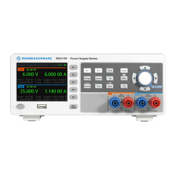
NGA100
Power Supply Series
Getting Started
(Æ1ç22)
5601890202
Version 06
Table of
Contents
Previous
Page
Next
Page
1
2
3
4
5
Advertisement
Table of Contents
Need help?
Do you have a question about the NGA100 Series and is the answer not in the manual?
Ask a question
Questions and answers
Related Manuals for R&S NGA100 Series
Power Supply R&S NGA102 Getting Started
(30 pages)
Power Supply R&S NGA141 Getting Started
(30 pages)
Power Supply R&S NGA142 Getting Started
(30 pages)
Power Supply R&S NGA101 Getting Started
(30 pages)
Power Supply R&S NGL-COM2A Getting Started
(29 pages)
Power Supply R&S NGM202 User Manual
(177 pages)
Power Supply R&S NGM Instrument Security Procedures
(7 pages)
Power Supply R&S NGL200 Getting Started
(29 pages)
Power Supply R&S NGL200 series User Manual
(150 pages)
Power Supply R&S NGL200 Series User Manual
(176 pages)
Power Supply R&S NGL200 Series Getting Started
(29 pages)
Power Supply R&S NGL200 Getting Started
(30 pages)
Power Supply R&S NGM200 Getting Started
(29 pages)
Power Supply R&S NGE100B Series User Manual
(105 pages)
Power Supply R&S NGE100B User Manual
(117 pages)
Power Supply R&S NGM-K106 User Manual
(176 pages)
This manual is also suitable for:
Nga102
Nga141
Nga142
Nga101
Table of Contents
Print
Rename the bookmark
Delete bookmark?
Delete from my manuals?
Login
Sign In
OR
Sign in with Facebook
Sign in with Google
Upload manual
Upload from disk
Upload from URL


Need help?
Do you have a question about the NGA100 Series and is the answer not in the manual?
Questions and answers