Table of Contents
Advertisement
Quick Links
Advertisement
Table of Contents

Related Manuals for R&S NGE100B


Summary of Contents for R&S NGE100B
- Page 1 ® R&S NGE100B Power Supply User Manual (Æ1=[2) 5601134302 Version 09...
- Page 2 Rohde & Schwarz GmbH & Co. KG. Trade names are trademarks of the owners. ® 5601.1343.02 | Version 09 | R&S NGE100B ® The following abbreviations are used throughout this manual: R&S NGE100B is abbreviated as R&S NGE100B. R&S® is abbrevi- ated as R&S.
-
Page 3: Table Of Contents
Release notes, open source acknowledgment............... 8 Conventions used in the documentation..............9 1.4.1 Typographical conventions....................9 1.4.2 Notes on screenshots..................... 9 2 Welcome to R&S NGE100B..............10 3 Important notes..................11 Symbols........................11 Ambient conditions.....................11 Measurement categories.................... 12 Mains voltage......................12 Limits..........................13 4 Getting started..................14... - Page 4 ® Contents R&S NGE100B 4.2.2 Switching on the instrument..................24 Trying out the instrument...................25 4.3.1 Selecting the channels....................25 4.3.2 Setting the output voltage and current limit..............25 4.3.3 Activating the channels output..................26 4.3.4 Storing/Recalling of instrument settings................26 5 Operating basics.................. 27 Display overview......................
- Page 5 ® Contents R&S NGE100B Advanced functions....................48 6.7.1 EasyArb.........................49 6.7.2 EasyRamp........................50 Store and recall......................52 Interfaces and protocols.................... 54 6.9.1 Network connection.......................54 6.9.1.1 LAN connection......................54 6.9.1.2 Wireless LAN connection....................56 6.9.2 USB connection......................58 6.9.3 LXI..........................60 6.9.4 SCPI..........................62 6.9.5 VISA..........................62 6.9.6...
- Page 6 ® Contents R&S NGE100B Measurement commands................... 93 Advanced operating commands................93 7.5.1 Arbitrary commands...................... 94 7.5.2 EasyRamp commands....................96 7.5.3 DIO commands......................97 Data and file management commands..............102 Firmware update....................... 102 8 Maintenance and support..............103 Maintenance......................103 Contacting customer support..................103 9 Applications..................105 Parallel and series mode..................
-
Page 7: Preface
The R&S NGE100B is intended for the development, production and verification of electronic components and devices in industrial, administrative, and laboratory environ- ments. Use the R&S NGE100B only for its designated purpose. Observe the operating conditions and performance limits stated in the data sheet. -
Page 8: Data Sheet
NGE100B Documentation overview www.rohde-schwarz.com/product/nge100b Getting started Introduces the R&S NGE100B power supply series and describes how to set up and start working with the instrument. The printed document is delivered with the instru- ment. User manual Contains the description of all instrument modes and functions. It also provides an... -
Page 9: Conventions Used In The Documentation
® Preface R&S NGE100B Conventions used in the documentation 1.4 Conventions used in the documentation 1.4.1 Typographical conventions The following text markers are used throughout this documentation: Convention Description "Graphical user interface ele- All names of graphical user interface elements on the screen, such as ments"... -
Page 10: Welcome To R&S Nge100B
All R&S NGE100B power supply series are equipped with a color LCD display (320 x 240 pixels resolution). The R&S NGE100B comes with a USB interface and optional LAN (LXI) interface. -
Page 11: Important Notes
® Important notes R&S NGE100B Ambient conditions 3 Important notes 3.1 Symbols Caution, general danger zone Ground PE terminal ON (supply voltage) OFF (supply voltage) Ground terminal 3.2 Ambient conditions The allowed operating temperature ranges from +0 °C to +40 °C (pollution category 2). -
Page 12: Measurement Categories
® Important notes R&S NGE100B Mains voltage allowed limit, overtemperature protection is triggered and the affected outputs are switched off automatically. Air circulation Do not obstruct the ventilation holes! 3.3 Measurement categories This instrument is designed for supplying power-on circuits that are only indirectly con- nected to the low voltage mains or not connected at all. -
Page 13: Limits
The maximum values for the instrument must not be excee- ded. The protection limits are listed on the front panel of the R&S NGE100B to ensure the safe operation of the instrument. -
Page 14: Getting Started
4 Getting started 4.1 Putting into operation This chapter describes the steps to set up the R&S NGE100B for the first time. Risk of injury and instrument damage The instrument must be used in an appropriate manner to prevent electric shock, fire, personal injury, or damage. -
Page 15: Safety
4.1.1 Safety Recommendations on secure operation The R&S NGE100B is designed to operate at local workplaces or in secured networks (LAN). It should not be accessible from the internet, because of a potential security risk, e.g. attackers could misuse or damage your device. -
Page 16: Intended Operation
® Getting started R&S NGE100B Putting into operation Risk of electric shock It is prohibited to disconnect the earthed protective connection inside or outside of the instrument! If it is assumed that a safe operation is no longer possible, the instrument must be shut down and secured against any unintended operation. - Page 17 ® Getting started R&S NGE100B Putting into operation The product may be operated only under the operating conditions and in the positions specified by the manufacturer, without the product's ventilation being obstructed. If the manufacturer’s specifications are not observed, this can result in electric shock, fire and/or serious personal injury, and in some cases, death.
-
Page 18: Unpacking And Checking The Instrument
Delivery package The package contents contain the following items: ● R&S NGE100B power supply preloaded with two 230 V fuses ● Four power cables ● Two 115 V fuses (replace the preloaded fuses with these fuses depending on the mains voltage, see Chapter 4.2.2, "Switching on the... -
Page 19: Bench Operation
Putting into operation 4.1.4.1 Bench operation On a benchtop, the R&S NGE100B can either lie flat or stand on its feet. As shown in Figure 4-1, feet on the bottom can be folded out to set the instrument in an inclined position. -
Page 20: Instrument Tour
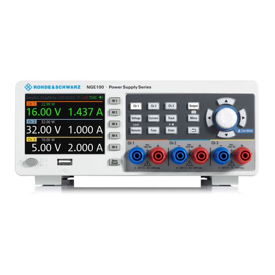
Operate R&S NGE100B power supply in an area where the ambient temperature is within +0 °C to +40 °C. The R&S NGE100B power supply is fan-cooled and must be installed with sufficient space along the sides to allow proper air circulation. Ensure that fan openings are unobstructed and airflow vents are unimpeded. - Page 21 ® Getting started R&S NGE100B Instrument tour Figure 4-2: Front panel of R&S NGE100B with 3 channels 1 = Display 2 = Function keys 3 = Rotary knob and arrow keys 4 = Output channels (see Table 4-2) 5 = USB connector...
-
Page 22: Rear Panel
The [Power] key switches the instrument on and off. 4.2.1.2 Rear panel Figure 4-3 shows the rear panel of the R&S NGE100B with its connectors. Figure 4-3: Rear panel of R&S NGE100B 7 = Ground terminal 8 = AC inlet with fuse holder... - Page 23 24 for more information. Voltage selector (9) Setting voltage selector The voltage selector is located at the bottom of the R&S NGE100B. On your first power-on connection, a yellow label sticker is attached over the inlet. Before peeling off the yellow label sticker, make sure the correct fuse rating is used for the mains voltage.
-
Page 24: Switching On The Instrument
The Digital Trigger I/O option (R&S NGE-K103) must be installed for this function to be available in the instrument. Kensington security slot (13) A Kensington lock can be anchored to the R&S NGE100B power supply housing to secure it to a workstation mechanically. 4.2.2 Switching on the instrument Before switching on the instrument, check that all the instructions in the “Basic Safety... -
Page 25: Trying Out The Instrument
By default, all output channels are turned off when the instrument is switched on to prevent connected loads from being damaged unintentionally. During startup, the R&S NGE100B is loaded with the last saved instrument settings from memory location "M1" and auto saved parameters. See Chapter 6.8, "Store... -
Page 26: Activating The Channels Output
® Getting started R&S NGE100B Trying out the instrument 4.3.3 Activating the channels output The output voltages can be switched on or off regardless of the operating mode of the instrument. To activate the channel output, press the [Output] key on the front panel followed by the desired channel key or vice versa. -
Page 27: Operating Basics
5 Operating basics 5.1 Display overview The following displays the screen layout of R&S NGE100B. It shows the output volt- age, current level and status bar information of the instrument. Figure 5-1: Screen layout of R&S NGE100B for two-channel and three-channel display... -
Page 28: Channel Display Area
® Operating basics R&S NGE100B Display overview Function Description DIO:xxxx Digital Trigger I/O (Digital Trigger I/O option R&S NGE-K103 must be installed). The "xxxx" refers to I/O status for DIO1, DIO2, DIO3, DIO4. If in use, the icon is highlighted in green. - Page 29 ® Operating basics R&S NGE100B Display overview Historical record information Available only in 2-channel instrument, the historical information at the bottom of the channel display area shows the maximum and minimum values for power ("W"), volt- age ("V") and current ("A").
-
Page 30: Front Panel Keys
For an overview of the front panel keys, see Figure 4-2. 5.2.1 Function keys The following keys can be categorized based on their functions. Figure 5-4: Function keys of R&S NGE100B Output and channel controls Navigation keys Instrument functions Memory functions... -
Page 31: Output And Channel Controls
® Operating basics R&S NGE100B Front panel keys 5.2.1.1 Output and channel controls Function keys Description [Ch 1], [Ch 2], [Ch 3] Selects the respective channel for output. Chapter 6.1, "Setting the voltage and current", on page 39. [Output] Master output switch - it turns output for all selected channels on or off. -
Page 32: Memory Functions
® Operating basics R&S NGE100B Front panel keys Function keys Description Remote Long press on the [Remote] key to switch from remote to local control mode. Fuse Toggles the fuse on/off. See Chapter 6.3.1, "Activating fuse", on page 41. 5.2.1.4 Memory functions These keys are dedicated for a specific preprogrammed function. -
Page 33: Arrow Keys
To exit live-mode, press the rotary knob. 5.2.3 Menu key The R&S NGE100B [Menu] key provides access to instrument's functions and general instrumental settings. You can also obtain the instrument and service information via the [Menu] key. - Page 34 ® Operating basics R&S NGE100B Front panel keys Figure 5-6: Main menu 2. Navigate the menu via the rotary knob or arrow keys. 3. Press the rotary knob or [Enter] key to enter the submenu. 4. Press key to return to the previous menu level or exit the menu mode if it is already at the main menu level.
- Page 35 Menu items Descriptions Interface Ethernet Configures the Ethernet interface. See Figure 6-15 The Ethernet option R&S NGE100B-K101 must be instal- led for this function to be available in the instrument. WLAN Configures the WLAN interface. See Figure 6-16. The WLAN option R&S NGE100B-K102 must be installed for this function to be available in the instrument.
-
Page 36: On-Screen Keyboard
® Operating basics R&S NGE100B Power derating 5.3 On-screen keyboard The on-screen keyboard allows you to input symbols and alphanumeric characters in the input field. It can be invoked whenever there is an input field. Figure 5-7: On-screen keyboard Invoke the on-screen keyboard as follows: 1. -
Page 37: Operation Modes
105. 5.5 Operation modes The R&S NGE100B operates in two different modes, i.e. CV and CC. The instrument switches automatically between CV and CC depending on the connected load. CV mode Figure 5-9 shows that if the instrument is in the range of voltage regulation, the output... - Page 38 ® Operating basics R&S NGE100B Operation modes Voltage regulation Figure 5-9: Current limit CC mode The current I corresponds to the current setting adjustable in the instrument. If I reaches I , the instrument switches to CC mode, i.e. the output current remains constant and limited to I even if the load increases.
-
Page 39: Instrument Functions
"EasyArb function" on page 49. The R&S NGE100B adjust voltage values between 0 V to 32.2 V with a step size of 0.01 V and current values between 0.003 A to 3.025 A with a step size of 0.001 A. -
Page 40: Activating The Channels Output
Selected channel key (Ch 1, Ch 2, Ch 3) illuminates. 2. Press [Output] key. The R&S NGE100B outputs the set voltage of the selected channel. Depending on the operating mode, the font text in the channel display area shows green in CV mode and red in CC mode. -
Page 41: Electronic Fuse
Figure 6-3: Output of Ch 3 in CV and CC mode 6.3 Electronic fuse To protect a connected, sensitive output in general, the R&S NGE100B power supply includes an electronic fuse which can be switched on individually for each channel. -
Page 42: Fuse Delay, Fuse Linking
41 for more information. Access: 1. Press [Menu] key. 2. Select "Output" > "Fuse" menu item. The R&S NGE100B displays the "Fuse" dialog. See Figure 6-5. Figure 6-5: Fuse dialog 3. Set "Fuse Delay" to a desire value. -
Page 43: Tracking Function
The tracking adjustments are applied to the two 20 V supplies so that the + and - 20 V supplies can be adjusted together. 1. Press [Track] key. The R&S NGE100B activates the tracking function and the [Track] key illuminates. Previous selected channel and [Voltage] keys are also illuminated. 2. Press the tracked channel to be tracked. -
Page 44: Protection
(OPP) settings for each channel. With both function activated, the R&S NGE100B protects itself and the load in case of voltage or power overloads. If protection is tripped, a red flashing OVP or OPP indicator is displayed on the respec- tive channel. -
Page 45: Digital Trigger I/O
4. Set the desired voltage for OVP. You can set a value from 0 V to 32.5 V. The R&S NGE100B turns off the respective channel when the measured voltage exceeded the preset value. 5. Set the OPP mode for the desired channel. - Page 46 ® Instrument functions R&S NGE100B Digital trigger I/O R&S NGE-K103 (order number: 5601.2227.03) option is required for the Digital Trigger I/O. The four data lines of the digital I/O interface are mutually independent and can be used as trigger input or trigger output separately. See Figure 4-3.
- Page 47 ® Instrument functions R&S NGE100B Digital trigger I/O Table 6-2: Trigger out parameters and conditions Trigger out parameters Trigger conditions Description Channel Ch 1, Ch 2, Ch 3 Output channel selected to monitor for trig- ger condition. Condition Trigger Output On...
-
Page 48: Advanced Functions
6-2. 7. Set the desired "Logic" state. 8. Set the "Status" to "Enabled". The R&S NGE100B enabled the selected DIO interface and monitor or feedback the trigger condition on the selected channel. 9. Set the "Master Enable" to "Enabled". The "Master Enable" is the master DIO interface which activates or deactivates all the DIO interfaces. -
Page 49: Easyarb
3. Set the desired repetition cycle for the EasyArb function. 4. Set the desired data points for the EasyArb function. The R&S NGE100B displays the number of EasyArb entry points in the EasyArb table. 5. Configure the EasyArb table with the desired values for voltage, current and dura- tion. -
Page 50: Easyramp
Select "Apply" to save EasyArb configuration. 6.7.2 EasyRamp With EasyRamp, the R&S NGE100B provides you the operating condition to output a constant rise of the supply voltage. The output voltage can be increased continuously within a 10 ms to 10 s timeframe. See Figure 6-11. - Page 51 2. Select the desired channel. 3. Set the selected channel to "Enabled". The R&S NGE100B enabled the EasyRamp function for the selected channel. Note: If selected channel is set disabled, corresponding output state of the selected channel is also disabled.
-
Page 52: Store And Recall
Upon power-up, the instrument loads the stored settings from memory location M1 with the exception on EasyArb parameters. Auto saved parameters are also applied during startup. The R&S NGE100B output state of all channels (Ch 1, Ch 2, Ch 3) is disabled when the recall function is activated. Auto save instrument settings... - Page 53 R&S NGE100B Store and recall The R&S NGE100B displays a message "Store device settings: select any [Mx] key" in the status bar. Figure 6-13: Store instrument settings 2. Press any of the memory keys ([M1], [M2], [M3], [M4], [M5]) to store the instrument settings.
-
Page 54: Interfaces And Protocols
R&S NGE100B Interfaces and protocols 6.9 Interfaces and protocols There are various of ways how the R&S NGE100B can be remotely accessed and con- trolled. Access: 1. Press [Menu] key. 2. Select "Interface" menu item to configure the required interface. - Page 55 By default, automatic configuration is set in the instrument. For manual configuration, select "Ethernet" menu item The R&S NGE100B displays the "Ethernet" dialog. Figure 6-15: Ethernet dialog 3. Select "DHCP & Auto-IP" for "IP Mode".
-
Page 56: Wireless Lan Connection
Power: 19.5 dBm typical Instrument option R&S NGE-K102 (order number: 5601.2210.03) option is required to connect the R&S NGE100B to a network via WLAN connection. Wireless LAN option is only available for instrument with serial number below 110000. User Manual 5601.1343.02 ─ 09... - Page 57 An alterative to connection in local area network is wireless LAN connection. With the presence of an authenticated Wi-Fi signal, the R&S NGE100B automatically connects to a network and navigation can be made via the web browser according to the WLAN IEEE 802.11 b/g/n standards.
-
Page 58: Usb Connection
● "TMC": USB Test & Measurement class 3. Press [Enter] key to confirm the settings. The R&S NGE100B displays message to prompt the user to restart the instrument to apply the changes. 4. Restart the R&S NGE100B to apply changes. - Page 59 Interfaces and protocols The USB virtual COM port (USB-VCP) is a software interface that allows the communi- cation to the R&S NGE100B using any terminal program (e.g. HMExplorer) via SCPI commands once the corresponding Windows drivers have been installed. The actual USB-VCP driver and software HMExplorer can be downloaded for free from the prod- uct homepage (http://www.rohde-schwarz.com/product/nge100b).
-
Page 60: Lxi
® Instrument functions R&S NGE100B Interfaces and protocols Figure 6-19: Device manager 6.9.3 LXI LAN extension for instrumentation (LXI) is a platform for measuring devices and test systems based on standard Ethernet technology. LXI is to be the LAN-based succes- sor to GPIB and combine the advantages of Ethernet with the simple and familiar fea- tures of the GPIB. - Page 61 Class A and B devices can send and receive software triggers through LAN messages and communicate with each other without using the controller. The power supplies of the R&S NGE100B series meet the general requirements of the LXI Class C and correspond to the version 1.5 (LXI Core 2016). Advanced features are not supported.
-
Page 62: Scpi
® Instrument functions R&S NGE100B Interfaces and protocols Figure 6-21: Instrument web browser view 6.9.4 SCPI SCPI (Standard Commands for Programmable Instruments) commands - messages - are used for remote control. Commands that are not taken from the SCPI standard fol- low the SCPI syntax rules. -
Page 63: General Instrument Settings
2. To switch back to the local mode, press [Remote] key to release the remote control mode. 6.10 General instrument settings The following chapters provide the general instrument information and utilities services in R&S NGE100B. User Manual 5601.1343.02 ─ 09... -
Page 64: Instrument Information
The last registered date when calibration was car- ried out on the instrument. "MAC Address" MAC address of the network interface. "Export OSA to USB" The open-source acknowledgment (OSA) of the R&S NGE100B can be exported to USB stick for ref- erence. User Manual 5601.1343.02 ─ 09... -
Page 65: General Instrument Settings
6.10.2 General instrument settings General instrument settings such as keypad fallback time, screen display brightness and buzzer setting are provided. Access: ► Select "General" menu item. The R&S NGE100B displays the "General" dialog. See Figure 6-23. Figure 6-23: General dialog General instrument settings... -
Page 66: Reset Instrument
6.10.4 Reset instrument This function resets the instrument to factory default settings. The following settings are reset to default: ► Select "Reset" menu item. The R&S NGE100B displays the "Reset" dialog. See Figure 6-25. User Manual 5601.1343.02 ─ 09... -
Page 67: System Test
This function provides a system test to check the instrument working conditions for screen color display, key backlight, beeper and cooling fan. Access: ► Select "System Test" menu item. The R&S NGE100B displays the "System Test" dialog. See Figure 6-26. Figure 6-26: System test dialog... -
Page 68: Updating The Firmware
3. Connect the USB flash drive to the USB port of the instrument and wait for ten sec- onds. 4. Press [Menu] key. 5. Select "Utilities" > "Update" menu item. If firmware file is found, the R&S NGE100B displays the "Update" dialog. See Fig- 6-27. Figure 6-27: Update dialog 6. -
Page 69: Help
6. Wait for the completion of the update process. It takes a few minutes to complete the firmware update process. 6.10.7 Help The "Help" dialog provides the internet link and QR code for the latest R&S NGE100B information. 1. Select "Help" menu item. -
Page 70: Remote Control Commands
This chapter provides the description of all remote commands available for the R&S NGE100B series. The commands are sorted according to the menu structure of the instrument. A list of commands in alphabetical order is given in the "List of Command"s at the end of this documentation. - Page 71 ® Remote control commands R&S NGE100B Common setting commands Parameters: <Value> Range: 0 to 255 *ESR? Event status read Returns the contents of the event status register in decimal form and then sets the reg- ister to zero. Return values: <Contents>...
- Page 72 ® Remote control commands R&S NGE100B Common setting commands *SRE <Contents> Service request enable Sets the service request enable register to the indicated value. This command deter- mines under which conditions a service request is triggered. Parameters: <Contents> Contents of the service request enable register in decimal form.
-
Page 73: System Commands
® Remote control commands R&S NGE100B System commands Parameters: <Number> Range: 0..4 See also "Store instrument settings" on page 52. *RCL <Number> Recall Loads the instrument settings from an internal memory identified by the specified num- ber. The instrument settings can be stored to this memory using the command *SAV with the associated number. - Page 74 ® Remote control commands R&S NGE100B System commands SYSTem:OPTion? This command returns the list of options installed on the instrument. Return values: <arg0> Usage: Query only SYSTem:TEST:BEEPer The instrument runs the system test: Beeper Test. Usage: Event SYSTem:TEST:FANCtrl The instrument runs the system test: Fan Control Test.
- Page 75 ® Remote control commands R&S NGE100B System commands SYSTem:COMMunicate:WLAN:CONNect The instrument connects to the predefined wireless access point. Usage: Event Options: R&S NGE-K102 Instrument with serial number below 110000 SYSTem:COMMunicate:WLAN:DISConnect The instrument stops the connection to the predefined wireless access point.
-
Page 76: Configuration Commands
® Remote control commands R&S NGE100B Configuration commands SYSTem:COMMunicate:WLAN:SSID <arg0> This command defines or queries the SSID string of the access point when the wire- less interface works as a client. Parameters: <arg0> Options: R&S NGE-K102 Instrument with serial number below 110000 7.3 Configuration commands... - Page 77 ® Remote control commands R&S NGE100B Configuration commands Example: Selecting a channel You can select a channel either with an OUTput parameter, or just by the channel number. This example lists all ways how you can select and query a selected channel.
-
Page 78: Voltage Setting
® Remote control commands R&S NGE100B Configuration commands Example: INSTrument OUTPut1 INSTrument OUTP1 Selects the output channel as Ch 1. INST? -> 2 Return the output channel as Ch 2. 7.3.2 Voltage setting The SOURce:VOLTage subsystem contains the commands for setting the voltage of the output channel. -
Page 79: Current Setting
® Remote control commands R&S NGE100B Configuration commands MAXimum 32.200E+01 Default unit: V Example: VOLT 10 Set the voltage value to 10 V. VOLT? -> 10 Return the voltage value of the selected channel. 7.3.3 Current setting The SOURce:CURRent subsystem contains the commands for setting the current limit of the output channel. -
Page 80: Combined Voltage And Current Settings
® Remote control commands R&S NGE100B Configuration commands 7.3.4 Combined voltage and current settings The APPLy subsystem provides a command that enables you to set the current and voltage of a channel in one step. APPLy <arg0> This command defines or queries the voltage and current value of the selected chan- nel. - Page 81 ® Remote control commands R&S NGE100B Configuration commands Example: Activating the channels You can activate a selected channel and turn on or off the outputs either individually or all outputs simultaneously. This example lists all ways how you can activate and query the outputs.
- Page 82 ® Remote control commands R&S NGE100B Configuration commands OUTPut:GENeral <arg0> This command activates or queries the instrument master output state. If the master output state is activated, the Output key on the front panel will be illumi- nated. Parameters: <arg0>...
-
Page 83: Fuse Setting
® Remote control commands R&S NGE100B Configuration commands OUTPut:SELect <arg0> This command activates or queries the instrument channel state of the previous selected channel. If the selected channel is activated, the respective channel key (i.e. Ch 1, Ch 2, Ch 3) on the front panel will be illuminated. - Page 84 ® Remote control commands R&S NGE100B Configuration commands Example: Configuring fuses This example contains all commands to configure and query the fuse states and set- tings. // ************************************************ // Activate a fuse // ************************************************ INST OUT1 // selects a channel and activates the overcurrent protection...
- Page 85 ® Remote control commands R&S NGE100B Configuration commands FUSE:LINK 2 // queries the combined overcurrent protection of the selected channel FUSE:LINK? 2 // response 1 // ************************************************ // Unlink linked overcurrent protection // ************************************************ FUSE:UNLink 2 // queries the combined overcurrent protection of the selected channel...
- Page 86 ® Remote control commands R&S NGE100B Configuration commands Example: INST OUT1 FUSE:LINK 2 Fuse Ch 1 is linked with Ch 2. FUSE:LINK? 2 -> 1 If the fuse of Ch 1 is linked with Ch 2, a "1" is returned.
-
Page 87: Ovp Setting
® Remote control commands R&S NGE100B Configuration commands Fuse will be activated. Fuse will be deactivated. *RST: OFF | 0 Example: INST OUT1 FUSE ON Fuse of Ch 1 is activated FUSE? -> 1 Return fuse state of the selected channel. - Page 88 ® Remote control commands R&S NGE100B Configuration commands Example: Configuring the overvoltage protection // ************************************************ // Set the overvoltage protection value // ************************************************ INST OUT1 //activates the OVP of the previous selected channel VOLT:PROT 1 // selects a channel and sets the OVP...
- Page 89 ® Remote control commands R&S NGE100B Configuration commands [SOURce:]VOLTage:PROTection:MODE <arg0> This command defines or queries the OVP mode for the previous selected channel. Parameters: <arg0> MEASured | PROTected MEASured The OVP switches off if the measured value exceeds the thresh- old.
-
Page 90: Opp Setting
® Remote control commands R&S NGE100B Configuration commands Example: INST OUT1 VOLT:PROT ON OVP of Ch 1 is activated. VOLT:PROT? -> 1 Return the OVP state of the selected channel. [SOURce:]VOLTage:PROTection:LEVel <Voltage> This command defines or queries the OVP value of the previous selected channel. - Page 91 ® Remote control commands R&S NGE100B Configuration commands Example: Configuring the overpower protection // ************************************************ // Set the overpower protection value // ************************************************ INST OUT1 //activates the OPP of the previous selected channel POW:PROT 1 // selects a channel and sets the OPP...
- Page 92 ® Remote control commands R&S NGE100B Configuration commands Set the OPP value to maximum. Default unit: W Example: INST OUT1 POW:PROT:LEV 5 Set the OPP value of channel 1 to 5 W. POW:PROT:LEV? -> 5 Return the selected channel OPP value.
-
Page 93: Measurement Commands
® Remote control commands R&S NGE100B Advanced operating commands 7.4 Measurement commands The MEASure subsystem provides commands to query the voltage and current values of a channel. MEASure[:SCALar]:CURRent[:DC]? This command queries the measured current value of the previous selected channel. -
Page 94: Arbitrary Commands
The sequence starts at 1 V and 1 A for 1 sec, and both values are incremented each second by 1. The generated arbitrary waveform is transferred to Ch 1. When activated, the R&S NGE100B provides the arbitrary waveform at the output of the selected chan- nel, and repeats it 10 times. - Page 95 ® Remote control commands R&S NGE100B Advanced operating commands ARBitrary:DATA <arg0> Defines or queries the arbitrary points for channel 1. The dwell time between two points is from 10ms to 600s. Parameters: <arg0> <Voltage1, Current1, Time1, Voltage2, Current2, Time2,..., Volt- age128, Current128, Time128>...
-
Page 96: Easyramp Commands
® Remote control commands R&S NGE100B Advanced operating commands ARBitrary[:STATe] <arg0> This command activates/deactivates or queries the EasyArb state. ON: Ch 1 is ready to run arb waveform. Parameters: <arg0> {OFF | ON} EasyArb state is activated. EasyArb state is deactivated. -
Page 97: Dio Commands
® Remote control commands R&S NGE100B Advanced operating commands Parameters: <Time> Range: 0.010 to 10 *RST: 0.010 Default unit: s [SOURce:]VOLTage:RAMP[:STATe] <arg0> This command defines/queries the EasyRamp state for the previous selected channel. Parameters: <arg0> {OFF | ON} EasyRamp function is activated. - Page 98 ® Remote control commands R&S NGE100B Advanced operating commands TRIGger:IN:ARBitrary:DIO<IO> <arg0> This command sets or queries the operation mode when starting EasyArb by Trig IN. Suffix: <IO> 1..4 Parameters: <arg0> PULSe | LEVel PULSe Starts EasyArb when trigger signal activated.
- Page 99 ® Remote control commands R&S NGE100B Advanced operating commands Suffix: <IO> 1..4 Parameters: <arg0> Trigger input source from Ch 1. Trigger input source from Ch 2. Trigger input source from Ch 3. *RST: TRIGger:LOGic:DIO<IO> <arg0> This command sets or queries the trigger logic (Active High/Active Low) of the speci- fied Digital I/O line.
- Page 100 ® Remote control commands R&S NGE100B Advanced operating commands Trigger output is turned on. Trigger output is turned off. FUSetrip Trigger output is linked to fuse tripped event. VOLTlevel Trigger output is linked to a set voltage level event. CURRlevel Trigger output is linked to a set current level event.
- Page 101 ® Remote control commands R&S NGE100B Advanced operating commands TRIGger:OUT:SOURce:DIO<IO> <arg0> This command sets or queries the control source of the trigger output of the specified Digital I/O line. Suffix: <IO> 1..4 Parameters: <arg0> Trigger output source from Ch 1.
-
Page 102: Data And File Management Commands
® Remote control commands R&S NGE100B Firmware update 7.6 Data and file management commands The HCOPy subsystem contains commands for managing the output of the screen environment. HCOPy:DATA? This command queries current screen content. BMP format is supported. Return values: <arg0>... -
Page 103: Maintenance And Support
® Maintenance and support R&S NGE100B Contacting customer support 8 Maintenance and support 8.1 Maintenance Regular maintenance improves the life span of the instrument, the following chapter provides information on instrument maintenance. Cleaning Before cleaning the instrument, ensure that it has been switched off and the power cable is disconnected. - Page 104 ® Maintenance and support R&S NGE100B Contacting customer support Figure 8-1: QR code to the Rohde & Schwarz support page User Manual 5601.1343.02 ─ 09...
-
Page 105: Applications
A series connection may cause dangerous voltages. To increase output voltage and currents, it is possible to operate the channels in series or parallel mode. In general, the output voltages of R&S NGE100B to be combined are independent. 9.1.1 Series mode This type of interconnection adds the individual output voltages. -
Page 106: Parallel Mode
® Applications R&S NGE100B Parallel and series mode Figure 9-1: Example of series connection 9.1.2 Parallel mode If it is necessary to increase the total current, the power supply outputs must be wired in parallel. The maximum total current is the sum of the individual currents of all sour- ces connected in parallel. - Page 107 ® Applications R&S NGE100B Parallel and series mode Principles of operation in parallel mode Generally, a higher current will first be supplied from the channel with the higher output voltage. Once this channel reaches its power limit, the remaining current will be made available by the channel that is connected in parallel.
-
Page 108: Annex
® Additional basics on remote control R&S NGE100B Messages and command structure Annex A Additional basics on remote control A.1 Messages and command structure A.1.1 Messages Instrument messages are employed in the same way for all interfaces, if not indicated otherwise in the description. -
Page 109: Scpi Command Structure
® Additional basics on remote control R&S NGE100B Messages and command structure are device-specific, however, their syntax follows SCPI rules as permitted by the standard. Instrument responses Instrument responses (response messages and service requests) are messages which the instrument sends to the controller after a query. They can contain measurement results, instrument settings and information on the instrument status. - Page 110 ® Additional basics on remote control R&S NGE100B Messages and command structure Example: MEASure:CURRent? is equivalent to MEAS:CURR? Case-insensitivity Uppercase and lowercase notation only serves to distinguish the two forms in the man- ual, the instrument itself is case-insensitive. Optional mnemonics Some command systems permit inserting or omitting certain mnemonics in the header.
- Page 111 ® Additional basics on remote control R&S NGE100B Messages and command structure ● Text ● Character strings ● Block data The required parameters and the allowed value range are specified in the command description. Numeric values You can enter numeric values in the following form. Values exceeding the resolution of the instrument are rounded up or down.
- Page 112 ® Additional basics on remote control R&S NGE100B Messages and command structure Example: VOLTage:PROTection:MODE MEASured VOLTage:PROTection:MODE MEAS VOLTage:PROTection:MODE? Response: MEASured Strings Strings must always be entered in quotation marks (' or "). Example: SYSTem:COMMunicate:SOCKet:IPADdress "192.168.1.128" SYSTem:COMMunicate:SOCKet:IPADdress '192.168.1.128' Block data Block data are a transmission format which is suitable for the transmission of large amounts of data.
-
Page 113: Command Sequence And Synchronization
The controller can be forced to wait for the corre- sponding action. The R&S NGE100B series does not support parallel processing of remote commands. If OPC? returns a "1", the device is able to process new commands. -
Page 114: List Of Commands
® List of commands R&S NGE100B List of commands [SOURce:]CURRent[:LEVel][:IMMediate][:AMPLitude]..................79 [SOURce:]POWer:PROTection:CLEar......................92 [SOURce:]POWer:PROTection:LEVel......................91 [SOURce:]POWer:PROTection:TRIPped?.......................92 [SOURce:]POWer:PROTection[:STATe]......................92 [SOURce:]VOLTage:PROTection:CLEar......................90 [SOURce:]VOLTage:PROTection:LEVel......................90 [SOURce:]VOLTage:PROTection:MODE......................89 [SOURce:]VOLTage:PROTection:TRIPped?....................89 [SOURce:]VOLTage:PROTection[:STATe]......................89 [SOURce:]VOLTage:RAMP:DURation......................96 [SOURce:]VOLTage:RAMP[:STATe]........................ 97 [SOURce:]VOLTage[:LEVel][:IMMediate][:AMPLitude]..................78 *CLS.................................70 *ESE................................70 *ESR?................................71 *IDN?................................71 *OPC................................71 *OPT?................................71 *RCL................................73 *RST................................ - Page 115 ® List of commands R&S NGE100B MEASure[:SCALar]:CURRent[:DC]?....................... 93 MEASure[:SCALar]:POWer?........................... 93 MEASure[:SCALar][:VOLTage][:DC]?......................93 OTP:TRIPped?..............................83 OUTPut:GENeral............................. 82 OUTPut:MODE..............................82 OUTPut:SELect............................... 83 OUTPut[:STATe]...............................81 SYSTem:BEEPer[:IMMediate]......................... 73 SYSTem:COMMunicate:SOCKet:DHCP[:STATe].................... 74 SYSTem:COMMunicate:SOCKet:IPADdress?....................74 SYSTem:COMMunicate:WLAN:CONNect....................... 75 SYSTem:COMMunicate:WLAN:DISConnect....................75 SYSTem:COMMunicate:WLAN:IPADdress?....................75 SYSTem:COMMunicate:WLAN:PASSword..................... 75 SYSTem:COMMunicate:WLAN:SSID......................76 SYSTem:COMMunicate:WLAN[:STATe]......................75 SYSTem:LOCal..............................73 SYSTem:OPTion?............................74 SYSTem:REMote.............................73 SYSTem:RWLock............................
-
Page 116: Index
® Index R&S NGE100B Index Fuse delay ................. 42 Fuse linking ............... 42 Activate channel output ............. 40 FuseLink ................42 Activating fuse ..............41 Advanced commands Arbitrary commands ............ 94 General instrument settings ........63, 65 DIO commands ............97 Buzzer ................. - Page 117 ® Index R&S NGE100B Operation modes Setting the output voltage and Current limit ....25 Constant current (CC) ..........38 Storing/Recalling of instrument settings ..... 25 Constant voltage (CV) ..........37 Options ................65 Identification (remote) ..........71 Unpacking and checking the instrument ......18 Install option ..............
Need help?
Do you have a question about the NGE100B and is the answer not in the manual?
Questions and answers