
Subscribe to Our Youtube Channel
Related Manuals for Keysight 53147A


Summary of Contents for Keysight 53147A
- Page 1 Keysight 53147A/148A/149A Microwave Frequency Counter/Power Meter/DVM Operating and Programming Guide...
- Page 2 227.7103-5 (c), as applicable in any Do not proceed beyond a WARNING technical data. notice until the indicated conditions are fully understood and met. Keysight 53147A, 53148A, and 53149A Operating and Programming Guide...
-
Page 3: Serial Prefix Number
Serial Prefix Number This guide describes how to service the Keysight 53147A, 53148A, and 53149A. The information in this guide applies to instruments having the number prefix listed below, unless accompanied by a “Manual Updating Changes” package indicating otherwise. SERIAL PREFIX NUMBER:... - Page 4 ANY IMPLIED WARRANTIES OR CONDITIONS OF MERCHANTABILITY, SATISFACTORY QUALITY, AND FITNESS FOR A PARTICULAR PURPOSE. Keysight will be liable for damage to tangible property per incident up to the greater of $300,000 or the actual amount paid for the product that is the subject...
-
Page 5: Safety Symbols
Caution, risk of danger (refer to this manual for specific Warning or Caution Caution, risk of electric shock information) Earth (ground) terminal Frame or chassis (ground) terminal Alternating current (AC) Direct current (DC) Keysight 53147A, 53148A, and 53149A Operating and Programming Guide... -
Page 6: Safety Considerations
Failure to comply with these precautions or with specific warnings elsewhere in this manual violates safety standards for design, manufacture, and intended use of the instrument. Keysight Technologies assumes no liability for the customer’s failure to comply with these requirements. -
Page 7: Geräuschemission
When the product is tested with 8kV AD, 4kV CD and 4kV ID according to IEC801-2, a system error may occur that may affect measurement data made during these disturbances. After these occurrences, the system self-recovers without user intervention. Keysight 53147A, 53148A, and 53149A Operating and Programming Guide... -
Page 8: Waste Electrical And Electronic Equipment (Weee) Directive
To return this unwanted instrument, contact your nearest Keysight Service Center, or visit http://about.keysight.com/en/companyinfo/environment/takeback.shtml for more information. Sales and Technical Support To contact Keysight for sales and technical support, refer to the support links on the following Keysight websites: – www.keysight.com/find/counters (product-specific information and support, software and documentation updates) –... -
Page 9: Table Of Contents
..........27 Accessories Supplied and Available ......28 Keysight 53147A/148A/149A Operating and Programming Guide... - Page 10 Averages Setting Example ....... . 86 Keysight 53147A/148A/149A Operating and Programming Guide...
- Page 11 Parameter Form Column ....... . .142 Keysight 53147A/148A/149A Operating and Programming Guide...
- Page 12 ..... . 179 The Operation and Questionable Data Status Register Groups . . 182 Programming the Instrument for Status Reporting ....189 Keysight 53147A/148A/149A Operating and Programming Guide...
- Page 13 ........218 Keysight 53147A/148A/149A Operating and Programming Guide...
- Page 14 ........260 Keysight 53147A/148A/149A Operating and Programming Guide...
- Page 15 ........295 Keysight 53147A/148A/149A Operating and Programming Guide...
- Page 16 ........... 301 Keysight 53147A/148A/149A Operating and Programming Guide...
-
Page 17: List Of Figures
... .262 Figure 3-23 The Status Byte Register ..... .263 Keysight 53147A/148A/149A Operating and Programming Guide... - Page 18 ....294 Figure C-3 Removing and Installing Batteries ....296 Keysight 53147A/148A/149A Operating and Programming Guide...
-
Page 19: List Of Tables
Table B-3 Error Messages ......289 Keysight 53147A/148A/149A Operating and Programming Guide... - Page 20 THIS PAGE HAS BEEN INTENTIONALLY LEFT BLANK. Keysight 53147A/148A/149A Operating and Programming Guide...
-
Page 21: In This Guide
In This Guide In This Guide This book is the Operating and Programming Guide for the Keysight 53147A, 53148A, and 53149A. It consists of a table of contents, this preface, a quick-reference guide, four chapters, three appendices, and an index. -
Page 22: Contents And Organization
RS-232 serial interface. Append ix C “Using the Battery Option” explains how to use the instrument with the Battery option. “Index” Keysight 53147A/148A/149A Operating and Programming Guide... -
Page 23: Related Documents
For more information on frequency counters, refer to the following Series 200 Application Notes: – Fundamentals of Electronic Frequency Counters, Application Note 200, Keysight part number 02-5952-7506. – Understanding Frequency Counter Specifications, Application Note 200-4, Keysight part number 02-5952-7522. – Fundamentals of Time and Frequency Standards, Application Note 52-1, Keysight part number 02-5952-7870. -
Page 24: Types Of Service Available If Instrument Fails
In This Guide Types of Service Available if Instrument Fails If your instrument fails within one year of original purchase, Keysight will repair it free of charge. If your instrument fails after your one-year warranty expires, Keysight will repair it, or you can repair it yourself. -
Page 25: Repackaging For Shipment
(if available). Keysight notifies you when your failed instrument is received. If the instrument is to be shipped to Keysight for service or repair, be sure you do the following: – Attach a tag to the instrument identifying the owner and indicating the required service or repair. -
Page 26: Description Of The Microwave Frequency Counter/Power Meter/Dvm
The Keysight 53147A, 53148A, and 53149A are capable of measuring frequencies from 10 Hz to 125 MHz on Channel 1 and from 50 MHz to 20 GHz (53147A), 26.5 GHz (53148A), and 46 GHz (53149A) on Channel 2. These instruments are also... -
Page 27: Options
Specifications for the options are listed in Chapter 4, “Specifications”. Options ordered with the instrument are installed at the factory and are ready for operation on delivery. Refer to the “Retrofitting Options” chapter in the Keysight 53147A/ 148A/149A Assembly-Level Service Guide for information on installing options in the field. -
Page 28: Accessories Supplied And Available
– Power cord, 2.3 meters (Part number dependent upon destination country) – Power sensor cable (Keysight 11730A) – DVM test leads (Keysight 34132B) Accessories Available – Soft Carrying Case (Keysight P/N 53147-80016) – Automotive Power Adapter (Keysight P/N 53150-60214) – Battery (Keysight P/N 53150-80010) – GPIB Cables (Keysight 10833A/B/C/D) –... -
Page 29: Keysight 53147A/148A/149A Quick Reference Guide
The Quick Reference Guide is designed for experienced users of the Keysight 53147A, 53148A, and 53149A. It is intended to be used as a tool to trigger your memory. If you are using the instrument for the first time, it is recommended that you at least read Chapter 1, “Getting Started”... -
Page 30: Keysight 53147A/148A/149A Quick Reference Guide
* *.* = max. Counter RESOL 100 KHZ frequency BAUD > 2400 RESOL 1 MHZ BAUD > 1200 BAUD > 19200 BAUD > 14400 Rate + / – RATE FAST RATE RATE SLOW RATE HOLD Keysight 53147A/148A/149A Operating and Programming Guide... -
Page 31: Getting Started
Keysight 53147A/148A/149A Microwave Frequency Counter/ Power Meter/DVM Operating and Programming Guide Getting Started The Front Panel at a Glance The Front Panel Indicators at a Glance The Front Panel Menus at a Glance The Display Annunciators at a Glance The Display Special Characters at a Glance... -
Page 32: The Front Panel At A Glance
25 Resolution / Frequency Offset key 11 DVM + connector 26 Clear / Display Backlight On/Off key 12 DVM – connector 27 Reset/Local / Menu key 13 Zero key 28 Shift key 14 Display DVM key 29 Standby indicator Keysight 53147A/148A/149A Operating and Programming Guide... -
Page 33: The Front Panel Indicators At A Glance
(Rate key) and the Counter measurement resolution (Resol key). The flash rate of the LED provides a rough indication Chan of the number of Counter measurements that are being taken in a given Select period of time. Keysight 53147A/148A/149A Operating and Programming Guide... - Page 34 It is normal for the fan to run when the instrument is in Standby mode. Power is NOTE supplied to the timebase whenever the instrument is connected to a power source, and the fan runs to cool the power supply. Keysight 53147A/148A/149A Operating and Programming Guide...
-
Page 35: The Front Panel Menus At A Glance
HOLD HEAD > 8481D BAUD > 4800 HEAD > 8481A BAUD > 2400 HEAD> CUSTOM BAUD > 1200 HEAD> CUSTOM BAUD > 19200 HEAD> CUSTOM BAUD > 14400 GPIB ADDR > 0 to 30 Keysight 53147A/148A/149A Operating and Programming Guide... -
Page 36: The Display Annunciators At A Glance
(Rmt = Remote operation via GPIB; SRQ = Service ReQuest). Error Indicates that a front-panel key command is unacceptable in the current context. Indicates that all front-panel keys are redefined to the function printed above the Shift key. Keysight 53147A/148A/149A Operating and Programming Guide... - Page 37 Getting Started Annunciator Description Pwr Ref Indicates that the 1 mW power reference output is turned on. Shows the amount of charge in the batteries (if the Battery option is installed). Keysight 53147A/148A/149A Operating and Programming Guide...
-
Page 38: The Display Special Characters At A Glance
Menu option. To switch between the two, press the right arrow key when the right pointer ( ) is flashing, or press the left arrow key when the left pointer ( ) is flashing. Keysight 53147A/148A/149A Operating and Programming Guide... -
Page 39: The Rear Panel At A Glance
10 Battery power switch (Battery option only) Auxiliary connector (reserved) 11 Battery Charging LED (Battery option only) Battery option cover plate 12 EXT DC power-input connector (Battery option only) [a] The Auxiliary connector is not installed on standard production units. Keysight 53147A/148A/149A Operating and Programming Guide... -
Page 40: Operating The Instrument
Operating the Instrument The procedures in this section are designed to familiarize you with the instrument’s features and controls. Keysight suggests that you follow the steps for each of these procedures, even if you do not presently need to make any measurements or to adjust any of the instrument’s settings. - Page 41 The following legend defines the meanings of the icons used throughout this chapter. Legend Press key one time Result Indicator off and release Auto operation Indicator on Multiple key presses Connect signal Indicator flashing Disconnect signal Keysight 53147A/148A/149A Operating and Programming Guide...
- Page 42 To turn on the instrument, press and release the POWER button on the front panel. POWER Ch 12 Rel Freq Offset Ext Ref Hold Avg On Rate Rmt SRQ Watts Rel Pwr Standby Error Pwr Ref Offset Shift Ch 2 Freq Keysight 53147A/148A/149A Operating and Programming Guide...
- Page 43 Shift On/Off Ch 2 Freq Clear If your instrument has the Battery option, you can extend the length of time the NOTE instrument can operate from the batteries by turning off the display backlight. Keysight 53147A/148A/149A Operating and Programming Guide...
- Page 44 Getting Started Using the Menu The Keysight 53147A/148A/149A has one menu that you use to control a number of the instrument’s features and functions. Displaying the Menu To display the Menu, press the Shift key and then the Menu (Reset/Local) key, as shown below.
- Page 45 Menu (unless you’ve used the Menu to change another setting since you turned the instrument on), you don’t have to use the (up-arrow) key or the (down-arrow) key to get to it. Keysight 53147A/148A/149A Operating and Programming Guide...
- Page 46 The Menu also contains some items that provide information only (no settings are required [or possible] for these), such as Battery Voltage, Operation Hours, and information that identifies the instrument (Keysight model number, firmware version number, serial number, and installed option codes).
- Page 47 Getting Started Setting the Serial Port Baud Rate (Menu Example) Ch 2 Freq Shift Shift Menu Reset/ Local Ch 2 Freq Enter Keysight 53147A/148A/149A Operating and Programming Guide...
- Page 48 Getting Started Selecting the Counter Input Channel You can toggle between Counter Channels 1 and 2 by pressing the Chan Select key. Ch 1 Freq Chan Select Ch 2 Freq Chan Select Keysight 53147A/148A/149A Operating and Programming Guide...
- Page 49 The Channel 2 input path circuits contain sensitive GaAs semiconductors. To CAUTION prevent damage to these components, always adhere to standard ESD (Electro-Static Discharge) prevention procedures, and ensure that the maximum power specification for this channel (+27 dBm) is not exceeded. Keysight 53147A/148A/149A Operating and Programming Guide...
- Page 50 Channel 2 input on the CAUTION Keysight 53149A must be handled with care to prevent damage and/or contamination, especially since it acts as a wave guide as well as an electrical connection. Observe the following precautions when handling this...
- Page 51 You can vary the speed at which measurements are taken by varying the settings for Rate and Resolution (see “Setting the Measurement Rate” “Setting the Resolution for Frequency Measurements” on pages 61 and 63). Keysight 53147A/148A/149A Operating and Programming Guide...
- Page 52 When you are entering a value for Frequency Offset (or Power Offset), you can NOTE use the Reset key to restore all of the displayed digits to zero. These are the only two functions in which the Reset key has this effect. Keysight 53147A/148A/149A Operating and Programming Guide...
- Page 53 Getting Started Ch 2 Freq Ch 2 Freq Offset Offset On/Off Ch 2 Freq Shift Offset Shift Freq Offset Freq Resol Offset Freq Offset Rate Freq Offset Ch 2 Freq Enter Offset Keysight 53147A/148A/149A Operating and Programming Guide...
- Page 54 Getting Started Measuring Power The Keysight 53147A/148A/149A can measure signal power (the power and frequency ranges for power measurement are dependent on the power-sensor model used). To measure power, you must first set the Power Meter for the power-meter sensor (head) that you intend to use.
- Page 55 Getting Started Ch 2 Freq Shift Shift Menu Reset/ Local Ch 2 Freq Enter Keysight 53147A/148A/149A Operating and Programming Guide...
- Page 56 When the power of a signal applied to the Power Meter Input connector exceeds NOTE the maximum rated power for the Power Meter head, the Power Meter displays Ch 2 Freq Ch 2 Freq Display Power Keysight 53147A/148A/149A Operating and Programming Guide...
- Page 57 If a signal having an amplitude below the minimum specification is applied, the power annunciators display “LO” to indicate that the signal level is too low to be measured by this Power Meter. Keysight 53147A/148A/149A Operating and Programming Guide...
- Page 58 Rel Pwr key. It then subtracts this value from all subsequent readings and displays the difference until you press the Rel Pwr key again. Ch 2 Freq Ch 2 Freq Shift Shift Rel Pwr Ch 2 Freq Offset On/Off Rel Pwr Keysight 53147A/148A/149A Operating and Programming Guide...
- Page 59 Power Offset function is enabled first, and the offset value is then entered. However, the order doesn’t matter, so you can also enter the offset value first, and then turn the offset function on. Keysight 53147A/148A/149A Operating and Programming Guide...
- Page 60 Getting Started Ch 2 Freq Rel Pwr Ch 2 Freq Offset On/Off Offset Ch 2 Freq Shift Offset Shift Offset Offset Offset Offset Ch 2 Freq Enter Offset Keysight 53147A/148A/149A Operating and Programming Guide...
- Page 61 (frequency, power, and/or voltage). You can set the measurement rate to FAST, MED (medium), SLOW, or HOLD (single measurement taken each time you press the Reset/Local key). Ch 2 Freq Ch 2 Freq Shift Rate Ch 2 Freq Enter Hold Keysight 53147A/148A/149A Operating and Programming Guide...
- Page 62 (10 through 90) and the units position (0 through 9) are adjusted separately, and that you cannot set the number of averages to zero. Ch 1 Freq Offset Ch 1 Freq Enter Avg On Ch 1 Freq Enter Avg On Keysight 53147A/148A/149A Operating and Programming Guide...
- Page 63 As shown in the procedure in the diagram on the next page, the available resolution settings are 1 Hz (the default setting), 10 Hz, 100 Hz, 1 kHz, 10 kHz, 100 kHz, and 1 MHz. Keysight 53147A/148A/149A Operating and Programming Guide...
- Page 64 Getting Started Ch 2 Freq Freq Offset Resol Ch 2 Freq Enter Keysight 53147A/148A/149A Operating and Programming Guide...
- Page 65 The 53147A/148A/149A DVM can measure voltages up to ± 50VDC. CAUTION Applying voltages outside of the ± 60VDC range to the DVM inputs can damage the DVM.
- Page 66 Getting Started THIS PAGE HAS BEEN INTENTIONALLY LEFT BLANK. Keysight 53147A/148A/149A Operating and Programming Guide...
-
Page 67: Operating Your Instrument
Keysight 53147A/148A/149A Microwave Frequency Counter/ Power Meter/DVM Operating and Programming Guide Operating Your Instrument Introduction How this Instrument Works for You Summary of the Measurement Sequence Using the Selection Keys Using the Clear and Reset/Local Keys Other Function Selection Keys... -
Page 68: Introduction
Operating Your Instrument Introduction This chapter contains information and usage procedures for the front- panel keys, operating functions, and menus of the Keysight 53147A, 53148A, and 53149A. Chapter Summary – “How this Instrument Works for You” pg. 69 – “Summary of the Measurement Sequence”... -
Page 69: How This Instrument Works For You
– Automatically displays measurement(s) when you have selected a measurement function. – Accepts your entry for a menu item when you press the Enter key. You must press the Enter key to complete each setting and/or selection. – Saves user configuration settings. Keysight 53147A/148A/149A Operating and Programming Guide... -
Page 70: Summary Of The Measurement Sequence
Menu (Shift + Reset/Local) key to set the GPIB address. 9 If you intend to operate the instrument remotely using the serial interface, use the Menu (Shift + Reset/Local) key to adjust the serial port Baud rate. Keysight 53147A/148A/149A Operating and Programming Guide... -
Page 71: Using The Selection Keys
Pressing either of these keys repeatedly cycles through the list of settings. – Press the Sign (+/–) key to change the sign of numeric values. – Press the Enter key to accept the currently displayed setting and exit the Menu. Keysight 53147A/148A/149A Operating and Programming Guide... -
Page 72: Numeric Entry
– Press the Enter key to complete a numeric entry. (If you change the value of a numeric entry, but you forget to press the Enter key, the value of the entry is not changed.) Keysight 53147A/148A/149A Operating and Programming Guide... -
Page 73: Changing States
– Measurement Rate (Rate key) – Fast (FAST) – Medium (MED) – Slow (SLOW) – Hold (HOLD) – Resolution (Resol key) – 1 Hz, 10 Hz, 100 Hz, 1 kHz, 10 kHz, 100 kHz, 1 MHz Keysight 53147A/148A/149A Operating and Programming Guide... - Page 74 Enter key, the setting of the function is not changed.) The Sign key has no function and is ignored in menu selections and front-panel NOTE functions that have state-change selections only. Keysight 53147A/148A/149A Operating and Programming Guide...
-
Page 75: Using The Clear And Reset/Local Keys
Local Mode and enables all of the front-panel controls. Acknowledging Messages When a message is displayed, press the Reset/Local key, the Clear key, or the Enter key (after reading the message) to acknowledge it and erase it from the display. Keysight 53147A/148A/149A Operating and Programming Guide... -
Page 76: Other Function Selection Keys
Use the Selection keys in the manner described earlier in this chapter (see “Numeric Entry” “Changing States”) to adjust the settings for these functions. Detailed procedures for using the Resol, Freq Offset, Freq, Cal Factor, Rate, and Avg keys are provided later in this chapter. Keysight 53147A/148A/149A Operating and Programming Guide... - Page 77 Rel Freq key in the COUNTER section of the front panel to measure the difference in frequency between the current measurement and the measurement taken at the time you pressed the Rel Freq key (drift). Keysight 53147A/148A/149A Operating and Programming Guide...
- Page 78 – DAMAGE Display ±60 VDC – Display voltage measurement (DVM: Display DVM). Press the Display DVM key in the DVM section of the front panel to turn the voltage measurement function on and off. Keysight 53147A/148A/149A Operating and Programming Guide...
- Page 79 Frequency and power measurements can be displayed simultaneously, as can voltage and power measurements. Frequency measurements and voltage measurements can be displayed alone, but power measurements are always accompanied by either the frequency display or the voltage display. Keysight 53147A/148A/149A Operating and Programming Guide...
-
Page 80: Measuring Frequency
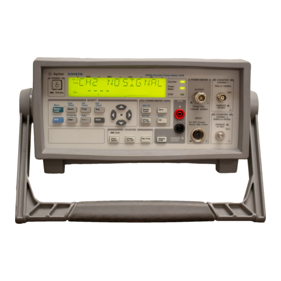
GPIB address, and CH2 NO SIGNAL. The Counter is now ready to measure the frequency of a signal applied to the Channel 2 input. Note that the Ch 2 and Freq annunciators are activated. 3 Connect an input signal to Channel 2. Keysight 53147A/148A/149A Operating and Programming Guide... - Page 81 If a signal is presently applied to the Channel 1 input, the measured frequency is then displayed. If no signal is applied, CH1 NO SIGNAL is displayed until an input signal is connected to the Channel 1 input connector. Keysight 53147A/148A/149A Operating and Programming Guide...
-
Page 82: Setting The Resolution And Measurement Rate
As a result, the flash rate of the Gate indicator changes when you change the resolution. The numerals shown for the value of the measurement are displayed in four groups of three digits, as shown below (the leading zero is suppressed): Ch 2 Freq Keysight 53147A/148A/149A Operating and Programming Guide... - Page 83 The setting you chose is now in effect. The number of digits displayed for the measurement is adjusted accordingly; you can observe the affect on measurement speed by monitoring the flash rate of the Gate indicator. Keysight 53147A/148A/149A Operating and Programming Guide...
-
Page 84: Setting The Measurement Rate
Enter The current rate setting is displayed (the current value and the indicator between the arrow keys are flashing to indicate that you can use the up- and down-arrow keys to change the setting). Keysight 53147A/148A/149A Operating and Programming Guide... - Page 85 The instrument computes the measurement and then displays the result (if averaging is enabled, the instrument displays the AVERAGING message while it computes the measurement). Press the Reset/Local key again each time you want to take an additional measurement. Keysight 53147A/148A/149A Operating and Programming Guide...
-
Page 86: Setting The Number Of Averages
+/– The current averages setting is displayed (the current value and the indicator between the arrow keys are flashing to indicate that you can use the up- and down-arrow keys to change the setting). Keysight 53147A/148A/149A Operating and Programming Guide... - Page 87 When the first set of averages is complete and the result is displayed, the instrument immediately takes another measurement, discards the oldest measurement included in the current average computation, recomputes the average and displays the new Keysight 53147A/148A/149A Operating and Programming Guide...
- Page 88 SLOW, MED, or HIGH. When the measurement rate is set to HOLD, the instrument performs a block-average computation instead of a running-average computation. Keysight 53147A/148A/149A Operating and Programming Guide...
-
Page 89: Measuring Relative Frequency
The value displayed when the Counter acquires the second signal is the frequency difference between the two signals. Keysight 53147A/148A/149A Operating and Programming Guide... -
Page 90: Offsetting A Frequency Measurement
Enter a value of 500 Hz. The flashing digit is the digit that currently has the focus. This means that you can change the value of the flashing digit using the up- and down-arrow keys. Keysight 53147A/148A/149A Operating and Programming Guide... - Page 91 (LO). If you enter the target frequency as a negative offset, the Counter displays the difference between the LO’s frequency and the target frequency. You can then adjust the LO until the Counter displays a value of zero. Keysight 53147A/148A/149A Operating and Programming Guide...
- Page 92 Operating Your Instrument The maximum value that can be entered for Frequency Offset is NOTE ±49,999,999,999 Hz. Keysight 53147A/148A/149A Operating and Programming Guide...
-
Page 93: Measuring Power
Watts. Selecting a Power Head (Sensor) There are a number of Keysight power heads that can be used with the Power Meter in this instrument. Choosing the appropriate power head is a matter of matching the head’s characteristics to the signal to be measured. - Page 94 When there is no signal applied to the power head, the Power Meter reads the NOTE noise level, as shown in the illustration above. This reading is generally below –25 dBm prior to zeroing and will vary. Keysight 53147A/148A/149A Operating and Programming Guide...
- Page 95 The instrument is shipped with calibration tables in nonvolatile memory for five of the supported power heads. The data points in these tables are almost always sufficient to provide accurate readings, so it is usually unnecessary to add or modify the values in the tables. Keysight 53147A/148A/149A Operating and Programming Guide...
- Page 96 Store key (Shift + Cal) to input the frequency value instead of using either the Freq or Cal Factor keys and entering a value manually. This saves time and has the same effect. Keysight 53147A/148A/149A Operating and Programming Guide...
-
Page 97: Modifying And Adding Calibration Factor Tables
Modifying and Adding Calibration Factor Tables The HEAD menu option provides access to preconfigured, editable calibration-factor tables for five models of Keysight power-sensor heads (models 8481A, 8481D, 8482A, 8485A, and 8487A) and three custom tables. You can modify the frequency/calibration-factor values in any of the data points for any power head, and you can input data to build new calibration tables (CUST 1, CUST 2, and CUST 3). -
Page 98: Table 2-1 Calibration Factor Data Point Modifications
(or add data points) by pressing the right-arrow key while a power-head model number is displayed and pressing the right-arrow key again when “LIST” is displayed. For instructions on entering or changing data, see “Numeric Entry” on page 72. Keysight 53147A/148A/149A Operating and Programming Guide... - Page 99 You can also use the right and left arrow keys to move between the digits of the frequency value and use the up and down arrow keys to change the values of these digits. Keysight 53147A/148A/149A Operating and Programming Guide...
- Page 100 Press the right arrow key once to display the model number. If your instrument’s model number is any number lower than 2060166-99, you should obtain and install the firmware kit (Keysight part number 53147-80018). 7 When you move the focus to the last d igit of the frequency value (the one...
- Page 101 To delete a data point entirely, set the calibration-factor to a value of 50 or NOTE lower. When you move to the next data point or exit the menu, the data point containing the =< 50 value is automatically deleted from the table. Keysight 53147A/148A/149A Operating and Programming Guide...
-
Page 102: Table 2-2 Calibration Table Data-Point Values
8 GHz 96.6 8481A 9 GHz 96.2 10 GHz 95.4 11 GHz 94.9 12.4 GHz 94.3 13 GHz 94.3 14 GHz 93.2 15 GHz 93.0 16 GHz 93.0 17 GHz 92.7 18 GHz 91.8 Keysight 53147A/148A/149A Operating and Programming Guide... - Page 103 8481D 9 GHz 99.5 10 GHz 98.6 11 GHz 98.7 12 GHz 99.0 12.4 GHz 99.1 13 GHz 98.9 14 GHz 99.4 15 GHz 98.9 16 GHz 99.1 17 GHz 98.4 18 GHz 100.1 Keysight 53147A/148A/149A Operating and Programming Guide...
- Page 104 0.3 MHz 99.5 1 MHz 99.3 3 MHz 98.5 10 MHz 98.5 8482A 30 MHz 98.1 100 MHz 97.6 300 MHz 97.5 1 GHz 97.0 2 GHz 95.0 3 GHz 93.0 4.2 GHz 91.0 Keysight 53147A/148A/149A Operating and Programming Guide...
- Page 105 97.0 17 GHz 96.7 18 GHz 96.6 19 GHz 96.0 20 GHz 96.1 21 GHz 96.2 22 GHz 95.3 23 GHz 94.9 24 GHz 94.3 25 GHz 92.4 26 GHz 92.2 26.5 GHz 92.1 Keysight 53147A/148A/149A Operating and Programming Guide...
- Page 106 98.1 12 GHz 97.9 13 GHz 98.0 14 GHz 98.2 15 GHz 97.7 16 GHz 96.8 17 GHz 97.0 18 GHz 96.3 19 GHz 95.9 20 GHz 95.2 21 GHz 95.6 22 GHz 95.5 Keysight 53147A/148A/149A Operating and Programming Guide...
- Page 107 92.0 37 GHz 92.4 38 GHz 90.9 39 GHz 90.3 40 GHz 91.4 41 GHz 90.6 42 GHz 89.9 43 GHz 89.1 44 GHz 88.1 45 GHz 86.9 46 GHz 85.8 47 GHz 85.4 Keysight 53147A/148A/149A Operating and Programming Guide...
- Page 108 Operating Your Instrument Table 2-2 Calibration Table Data-Point Values (continued) Power Head Model Number Frequency Calibration Factor 48 GHz 83.2 49 GHz 81.6 8487A (continued) 50 GHz 80.2 Keysight 53147A/148A/149A Operating and Programming Guide...
-
Page 109: Measuring Relative Power
(sensor), and then connect the second signal to the same power head. The value displayed when the Power Meter acquires the second signal is the power difference between the two signals. Keysight 53147A/148A/149A Operating and Programming Guide... -
Page 110: Offsetting A Power Measurement
Pwr Offset annunciator at the left side of the display activates, and the power-offset value is set to 00.00, as shown below: Ch 12 Rel Freq Watts Offset If the power-offset value was previously changed, the previous value is NOTE displayed instead of 00.00. Keysight 53147A/148A/149A Operating and Programming Guide... - Page 111 When you are entering a power- or frequency-offset value, you can use the NOTE Reset key to restore all of the displayed digits to zero. These are the only two functions in which the Reset key has this effect. Keysight 53147A/148A/149A Operating and Programming Guide...
-
Page 112: Measuring Voltage
Operating Your Instrument Measuring Voltage The Keysight 53147A/148A/149A included a digital voltmeter (DVM) that can measure voltages from – 50 VDC to +50 VDC. To measure voltage, use the following procedure: Voltage Measurement Example 1 If the instrument is not already turned on, connect the power cord to the power-input connector on the rear panel and to an appropriate power source (or, with the Battery option, turn on the Battery power switch). -
Page 113: Using The Menu
Operating Your Instrument Using the Menu The Keysight 53147A/148A/149A’s Menu makes it easy to control a number of the instrument’s features and functions. You use the Selection (arrow) keys to navigate to the setting you want to change and then to actually make the changes. - Page 114 – BATT VOLTAGE — Displays the current voltage level in the rechargeable battery packs (only if the Battery option is installed). – DO SELF TEST — Starts the sequence of built-in tests. Keysight 53147A/148A/149A Operating and Programming Guide...
- Page 115 However, you can change more than one setting if you wait to press the Enter key until you have made all the changes you need to make. Keysight 53147A/148A/149A Operating and Programming Guide...
- Page 116 Some of the menu items listed on the previous page provide information only (no settings are required [or possible] for these), such as Battery Voltage, Operation Hours, and information that identifies the instrument (Keysight model number, firmware version number, serial number, and installed option codes). These menu options are described in the remainder of this chapter and also in “The Front Panel...
- Page 117 The Counter has a built-in 50 kHz low-pass filter that can be enabled from the Menu to eliminate measurement distortions that result from noise in low-frequency signals. When the low-pass filter is enabled, signals above 50 kHz are attenuated. Keysight 53147A/148A/149A Operating and Programming Guide...
- Page 118 Power Meter Head Model (HEAD) 8481A, CUSTOM 1, CUSTOM 2, CUSTOM 3 GPIB Address (GPIB) 0-30 1 Hz, 10 Hz, 100 Hz; 1kHz, 10 kHz, Resolution (Resol key) 1 Hz 100 kHz, 1 MHz Keysight 53147A/148A/149A Operating and Programming Guide...
- Page 119 Frequency limits vary with model COUNTER: Offset On/Off key Off, On 00.0 GZ through 19.9 GZ, 26.4 GZ, or Frequency value (Freq key) 46.4 GZ (for 53147A,148A, and 149A 00.1 GZ (GHz) respectively) Calibration Factor (Cal Factor key) 80.0 through 110.0 (%) 100.0...
- Page 120 Menu, navigating to DO SELF TEST, and pressing the Enter key. The individual tests that comprise the Self Test, and the error messages that are displayed if problems are detected, are described in Appendix B, “Messages”. Keysight 53147A/148A/149A Operating and Programming Guide...
- Page 121 Power Head Selection (HEAD) The instrument’s Power Meter works with a number of different Keysight power heads. This menu option allows you to choose the model number of the power head you intend to use for the current measurement. The power-head models included in the menu are: 8481A, 8481D, 8482A, 8485A, and 8487A.
- Page 122 Operating Your Instrument THIS PAGE HAS BEEN INTENTIONALLY LEFT BLANK. Keysight 53147A/148A/149A Operating and Programming Guide...
-
Page 123: Programming
Commands for Displaying Results Programming the Instrument to Synchronize Measurements Writing SCPI Programs Programming Examples Command Reference :ABORt Command :CALibration Subsystem :DISPlay Subsystem Group Execute Trigger (GET) :INITiate Subsystem :INPut Subsystem :MEASure Subsystem :MEMory Subsystem [:SENSe] Subsystem Keysight 53147A/148A/149A Operating and Programming Guide... - Page 124 Programming [:SENSe]:FUNCtion Subtree :STATus Subsystem :SYSTem Subsystem :TRIGger Subsystem :UNIT Subsystem Common Commands Errors Keysight 53147A/148A/149A Operating and Programming Guide...
-
Page 125: Introduction
Introduction This chapter assumes you are familiar with the front-panel operation of the Keysight Technologies 53147A, 53148A, and 53149A. See Chapters 1 and 2 for detailed information about front-panel operation. You should use this chapter together with Chapters 1 and 2. Knowing how to control the instrument from the front panel and understanding the measurements you want to perform makes the programming task much easier. -
Page 126: Chapter Summary
207 – “:ABORt Command” pg. 208 – “:CALibration Subsystem” pg. 209 – “:DISPlay Subsystem” pg. 214 – “Group Execute Trigger (GET)” pg. 216 – “:INITiate Subsystem” pg. 217 – “:INPut Subsystem” pg. 219 Keysight 53147A/148A/149A Operating and Programming Guide... - Page 127 – “[:SENSe]:FUNCtion Subtree” pg. 237 – “:STATus Subsystem” pg. 241 – “:SYSTem Subsystem” pg. 248 – “:TRIGger Subsystem” pg. 251 – “:UNIT Subsystem” pg. 252 – “Common Commands” pg. 253 – “Errors” pg. 266 Keysight 53147A/148A/149A Operating and Programming Guide...
-
Page 128: How To Use This Chapter
“Programming the Instrument for Remote Operation”, there are programming examples provided in BASIC, Microsoft QuickBASIC, and Borland Turbo C.) However, whatever language you use, the command strings that control the instrument remain the same. Keysight 53147A/148A/149A Operating and Programming Guide... -
Page 129: Experienced Programmers
– Read the section titled “Programming the Instrument for Remote Operation” on page 151 for an overview of SCPI concepts as they relate to the Keysight 53147A, 53148A, and 53149A. Look at the flowcharts, which illustrate some of the decisions you must make when programming the Instrument. -
Page 130: Applications
173. – If you are going to write programs to transfer data between the instrument and an external computer, read the section titled “Overview of Command Types and Formats” on page 159. Keysight 53147A/148A/149A Operating and Programming Guide... -
Page 131: Assumptions
See Chapters 1 and 2 for detailed information about front-panel operation. Knowing how to control the instrument from the front panel and understanding the measurements you need to perform makes the programming task much easier. Keysight 53147A/148A/149A Operating and Programming Guide... -
Page 132: Related Documentation
Programming Related Documentation This section contains a list of documentation that relates to the use of the Keysight 53147A/148A/149A. Additional information that may be useful is contained in the following publications: 1 Beginner's Guide to SCPI (Keysight Part Number H2325-90002, July 1990 Edition). - Page 133 345 East 47th Street New York, NY 10017 USA 6 Hewlett-Packard Company, Tutorial Description of the Hewlett-Packard Interface Bus, 1987. To obtain a copy of this manual, contact the nearest Keysight Technologies Sales office. Keysight 53147A/148A/149A Operating and Programming Guide...
-
Page 134: Front Panel To Scpi Command Map
3-2), you must send the quotation marks with the command. Refer to the section titled “Using BASIC” on page 201 for details on how to use double quotes or single quotes to enclose the string parameter of a command. Keysight 53147A/148A/149A Operating and Programming Guide... -
Page 135: Figure 3-1 Front Panel Control To Scpi Command Map (Part 1 Of 2)
Shift + dBm/W Zero Display Zero Power Rel Pwr Store Display Power Offset On/Off Offset On/Off (Pwr) Display DVM Display Figure 3-1 Front Panel Control to SCPI Command Map (Part 1 of 2) Keysight 53147A/148A/149A Operating and Programming Guide... -
Page 136: Figure 3-1 Front Panel Control To Scpi Command Map (Part 2 Of 2)
12 SENSe:FUNCtion:ON “VOLT” SENSe:FUNCtion:OFF “VOLT” 13 [SENSe]:POWer:OFFSet:STATe 14 [SENSe]:FUNCtion:ON “POW” [SENSe]:FUNCtion:OFF “POW” 15 UNITs:POWer DBM UNITs:POWer W 16 [SENSe]:FUNCtion:ON “FREQ1” [SENSe]:FUNCtion:ON “FREQ2” Figure 3-1 Front Panel Control to SCPI Command Map (Part 2 of 2) Keysight 53147A/148A/149A Operating and Programming Guide... -
Page 137: Figure 3-2 Front Panel Menu To Scpi Command Map (Part 1 Of 2)
Clear PWR REF SAVE RECALL CH1 LPF BAUD PRESET Instrument ID OP HRS BATT VOLTAGE DO SELF TEST HEAD GPIB ADDR Figure 3-2 Front Panel Menu to SCPI Command Map (Part 1 of 2) Keysight 53147A/148A/149A Operating and Programming Guide... -
Page 138: Figure 3-2 Front Panel Menu To Scpi Command Map (Part 2 Of 2)
6 [:SENSe]:FILTer:FM:AUTO 7 :SYSTem:COMMunicate:SERial[:RECeive]:BAUD 8 *RST 9 *IDN? 10 See Service Manual 11 See Service Manual 12 *TST? 13 [:SENSe]:CORRection:CSET:SELect 14 :SYSTem:COMMunicate:GPIB[:SELF]:ADDRess Figure 3-2 Front Panel Menu to SCPI Command Map (Part 2 of 2) Keysight 53147A/148A/149A Operating and Programming Guide... -
Page 139: Command Summary
– SCPI Subsystem commands designed for the instrument in conformance with SCPI standards but not yet listed in the SCPI Standard—the commands defined Table 3-2 as “New.” – Details of all Keysight 53147A/148A/149A commands can be found in the section titled “Command Reference” on page 207. -
Page 140: Ieee 488.2 Common Commands
Table 3-1 lists the IEEE 488.2 Common Commands supported by the Keysight 53147A/148A/149A in alphabetical order by mnemonic, name, and function. More information concerning the operation of IEEE 488.2 status-reporting commands and structure can be found in the “Status Reporting”... -
Page 141: Table 3-1 Ieee 488.2 Common Commands
Executes an internal self-test and reports the results. *WAI Wait-to-Continue Makes the instrument wait until all pending operations (see Note) are completed before executing commands that follow the *WAI command. Note: Pending operations include measurements in progress. Keysight 53147A/148A/149A Operating and Programming Guide... -
Page 142: Keysight 53147A/148A/149A Scpi Subsystem Commands
The category of “New” consists of commands that could be: – SCPI approved but are not yet in the SCPI manual – Keysight approved and submitted for SCPI approval. – Not approved at all. The “New” commands operate as defined in this guide. -
Page 143: Table 3-2 Keysight 53147A/148A/149A Scpi Command Summary
See Measurement Instructions in this table. :INITiate Subsystem. Controls the initiation of measurements. :CONTinuous <Boolean> Sets the instrument for continuously initiated or user-initiated measurements. [:IMMediate] Event; no query. Causes the instrument to initiate and complete one full measurement cycle. Keysight 53147A/148A/149A Operating and Programming Guide... - Page 144 Programming Table 3-2 Keysight 53147A/148A/149A SCPI Command Summary (continued) Keyword/Syntax Parameter Form Std/New Comments :INPut Subsystem. Controls the characteristics of the instrument’s Channel 1 input port. :FILTer Subtree. Controls a filter that can be inserted in the path of the measurement signal.
- Page 145 Programming Table 3-2 Keysight 53147A/148A/149A SCPI Command Summary (continued) Keyword/Syntax Parameter Form Std/New Comments *The <function> and corresponding <parameters> and <source_list> are defined below: <function> <parameters> Std/New [,<source_list>] [:VOLTage][:DC]FREQuency [<expected_value>[, [,(@1) | (@2)] [,(@2)] <resolution>]] :POWer[:AC] [<expected_value>[, [,(@3)] <resolution>]] :VOLTage[:DC] <expected_value>...
-
Page 146: Table 3-2 Keysight 53147A/148A/149A Scpi Command Summary (Continued)
Programming Table 3-2 Keysight 53147A/148A/149A SCPI Command Summary (continued) Keyword/Syntax Parameter Form Std/New Comments [:SENSe] Subsystem setup commands. :AVERage Subtree. Configures the averaging function. [:STATe] <Boolean> Turns averaging ON and OFF. :COUNt <numeric_value> Specifies the number of measurements to combine when AVERage:STATe is ON. -
Page 147: Table 3-2 Keysight 53147A/148A/149A Scpi Command Summary (Continued)
Programming Table 3-2 Keysight 53147A/148A/149A SCPI Command Summary (continued) Keyword/Syntax Parameter Form Std/New Comments :FUNCtion Subtree. Selects the <sensor_function>(s) to be sensed by the instrument. [:OFF] <sensor_function>[,<sensor_function>] Selects the <sensor_function>(s) to be turned "[XNONe]FREQuency [1 | 2]" OFF. "[XNONe]POWer" [:ON] <sensor_function>[,<sensor_function>]... - Page 148 Programming Table 3-2 Keysight 53147A/148A/149A SCPI Command Summary (continued) Keyword/Syntax Parameter Form Std/New Comments :PTRansition <non-decimal numeric> | <NRf> Sets and queries the positive transition filter for the Operation status reporting structure. :PRESet Event; No query. Presets the enable registers and transition filters associated with the Operation and Questionable status reporting structures.
-
Page 149: Rst Response
<numeric_value>[frequency unit> [:SENSe]:FREQuency:OFFset:STATe <Boolean> [:SENSe]:FREQuency:RESolution <numeric_value>[frequency unit> 1 Hz [:SENSe]:FREQuency:TRACking <character_program_data> SLOW [:SENSe]:FUNCtion:OFF <sensor_function> “FREQuency 1”, “POWer 2” [:SENSe]:FUNCtion[:ON] <sensor_function> “FREQuency 2” [:SENSe]:POWer:AC:REFerence <numeric_value> [:SENSe]:POWer:AC:REFerence:STATe <Boolean> [:SENSe]:ROSCillator:SOURce INTernal | EXTernal <Boolean> INTernal :TRIGger[:SEQuence]:HOLDoff <numeric_value> Keysight 53147A/148A/149A Operating and Programming Guide... -
Page 150: Table 3-4 Unaffected By *Rst
Programming Table 3-4 Unaffected by *RST Item *PRE :MEMory:NSTates? :STATus subsystem—all command settings :SYSTem subsystem—all command settings Keysight 53147A/148A/149A Operating and Programming Guide... -
Page 151: Programming The Instrument For Remote Operation
This section provides remote-operation setup and programming information. You can use this information to configure the instrument to operate as a remote device. Most of this chapter deals with programming the Keysight 53147A, 53148A, and NOTE 53149A using SCPI and IEEE 488.2 commands. With two minor exceptions, the... -
Page 152: Connecting The Instrument To A Computer
Connecting With the GPIB To connect the instrument to a computer using the GPIB, install an GPIB cable (such as the Keysight 10833A cable) between the two units, as shown in Figure 3-3. Computer (Rear Panel) - Page 153 SAV 0. The settings in SAV 0 are recalled each time the instrument is turned on. Keysight 53147A/148A/149A Operating and Programming Guide...
-
Page 154: Ieee 488.1 Interface Capabilities
The Keysight 53147A, 53148A, and 53149A have the following IEEE 488.1 Interface capabilities: Connecting With the RS-232 Serial Interface The Keysight 53147A, 53148A, and 53149A use an RJ12 modular connector for the RS-232 interface. This connector is accessible through the back panel of the instrument, as shown in Figure 3-4. - Page 155 DB25F connector, and the adapter body, or wiring shroud. Wire the RJ12 receptacle to the DB25F connector according to the diagrams in Figure 3-5, and then assemble the adapter according to the instructions included in the kit. Keysight 53147A/148A/149A Operating and Programming Guide...
-
Page 156: Figure 3-5 Wiring The Rj12/Db25 Adapter (1 Of 2)
BLK (TXD) RED (RXD) (Viewed from front side of the connectors) SPC Technology Voltrex Brand Part number MAK206 F DB-25F (female) to RJ12 (male) Adapter Figure 3-5 Wiring the RJ12/DB25 Adapter (2 of 2) Keysight 53147A/148A/149A Operating and Programming Guide... -
Page 157: Figure 3-6 Assembling The Cable
Assembling the Cable 4 Connect either end of the cable to the adapter by inserting the RJ12 plug into the receptacle on the adapter. This cable can be purchased from Keysight as part number 53150-60215. NOTE Keysight 53147A/148A/149A Operating and Programming Guide... -
Page 158: Remote/Local Operation
The Reset/Local key can be used to manually return the instrument to local control (if local-lockout is off). When the instrument is in Local mode, the front-panel Rmt indicator in the display is off. Keysight 53147A/148A/149A Operating and Programming Guide... -
Page 159: Overview Of Command Types And Formats
Programming Overview of Command Types and Formats There are two types of Keysight 53147A/148A/149A programming commands: IEEE 488.2 Common Commands and Standard Commands for Programmable Instruments (SCPI). The format of each type of command is described in the following paragraphs. (Refer to the section titled “Command Summary”... -
Page 160: Elements Of Scpi Commands
NOTE: sp = space. ASCII character decimal 32 Figure 3-8 Simplified Program Command Syntax Diagram Keysight 53147A/148A/149A Operating and Programming Guide... -
Page 161: Common Command Syntax
The command syntax shows most keywords as a mixture of upper- and lowercase letters. Uppercase letters indicate the abbreviated spelling for the command. For better program readability, you may send the entire keyword. The Keysight 53147A/148A/149A accepts either command form and is not case sensitive. -
Page 162: Optional Keyword
:SENS:FREQ:RES :FREQ:RES Parameter Types Table 3-5 contains explanations and examples of parameter types. Parameter types may be numeric value, Boolean, literal, NRf, string, non-decimal numeric, or arbitrary block. Keysight 53147A/148A/149A Operating and Programming Guide... - Page 163 The following BASIC statement sends a command containing a <string> parameter: OUTPUT 703;"FUNC ‘FREQ’" <non-decimal Format for specifying hexadecimal (#H1F), octal (#Q1077), and binary (#B10101011) numbers using ASCII numeric> characters. May be used in :STATus subsystem commands. Keysight 53147A/148A/149A Operating and Programming Guide...
-
Page 164: Parameter Separator
AVER:COUN? MIN), the command returns the minimum acceptable count. If you send the MAX parameter, the command returns the maximum level currently available. Be sure to place a space between the question mark and the parameter. Keysight 53147A/148A/149A Operating and Programming Guide... -
Page 165: Suffixes
Suffix Multipliers Definition Mnemonic Name 1E15 PETA 1E12 TERA GIGA MEGA MA ( or M for OHM and HZ) KILO 1E-3 MILLI M (except for OHM and HZ) 1E-6 MICRO 1E-9 NANO 1E-12 PICO Keysight 53147A/148A/149A Operating and Programming Guide... -
Page 166: Command Terminator
A command may be terminated with a <new line> (ASCII character decimal 10), an EOI (End-of-Identify) asserted concurrent with last byte, or an EOI asserted concurrent with a <new line> as the last byte. Keysight 53147A/148A/149A Operating and Programming Guide... -
Page 167: Using Multiple Commands
Subsequent commands, separated by “;”, are referenced to the same level as the preceding command if no “:” is present immediately after the command separator (the semicolon). Keysight 53147A/148A/149A Operating and Programming Guide... - Page 168 :SENS:AVER:COUN 5 :INIT:CONT OFF If the “:”(which is following the “;” and is in front of INIT) is omitted, the instrument assumes that the second command is “:SENS:AVER:INIT:CONT OFF” and generates a syntax error. Keysight 53147A/148A/149A Operating and Programming Guide...
-
Page 169: Overview Of Response Message Formats
When multiple queries are sent in the same program message, the groups of data corresponding to each query are separated by a semicolon. Note that a <new line> ^END is always sent as a response message terminator. response data <new line> ^END Keysight 53147A/148A/149A Operating and Programming Guide... -
Page 170: Response Message Data Types
16 digits, 1 sign). <NR2> This numeric representation has an explicit radix point. <digit> <digit> − The maximum number of characters in <NR2> response data is 17 (maximum 15 mantissa digits, 1 sign, 1 decimal point). Keysight 53147A/148A/149A Operating and Programming Guide... - Page 171 A single ASCII-encoded byte, 0 or 1, is returned for the query of settings that use <Boolean> parameters. <literal> ASCII-encoded bytes corresponding to the short form of the literal used as the command parameter. Keysight 53147A/148A/149A Operating and Programming Guide...
- Page 172 The “2” indicates the number of digits that follow and the two digits “08” indicate the number of data bytes to be transmitted. A zero-length block has the format: #0<new line>^EOI <new line> is defined as a single ASCII-encoded byte corresponding to 10 decimal. Keysight 53147A/148A/149A Operating and Programming Guide...
-
Page 173: Status Reporting
Programming Status Reporting The Keysight 53147A, 53148A, and 53149A status registers conform to the SCPI and IEEE 488.2 standards. Figure 3-12 shows all of the status-register groups and queues in the instrument. This is a high level diagram that does not show all the registers that are contained in each group. -
Page 174: Figure 3-12 53147A/148A/149A Scpi Status Reporting Summary Functional Diagram
Using Internal Reference Not Used ( 2048 ) Acquiring ( 4096 ) Locked Not Used 13 to 15 (Use :STATus:OPERation Commands to control and read registers.) Figure 3-12 53147A/148A/149A SCPI Status Reporting Summary Functional Diagram Keysight 53147A/148A/149A Operating and Programming Guide... -
Page 175: Status Byte Register And Service Request Enable Register
The entire Status Byte Register can be cleared by sending just the *CLS command to the instrument in a program message. Table 3-8 lists the Status Byte Register bits and briefly describes each bit. Keysight 53147A/148A/149A Operating and Programming Guide... - Page 176 This bit is set TRUE (one) when the instrument is ready to accept a request by the external computer to output data bytes; that is, the Output Queue is not empty. This bit is set FALSE (zero) when the Output Queue is empty. Keysight 53147A/148A/149A Operating and Programming Guide...
- Page 177 Use *SRE to write to this register and *SRE? to read this register. Use *SRE 0 to clear the register. A cleared register does not allow status information to generate the service requests. (Power-on also clears this register.) Keysight 53147A/148A/149A Operating and Programming Guide...
-
Page 178: Standard Event Status Register Group
Table 3-9 Standard Event Status Register Weight Symbol Description Operation Complete — (RQC) Not used because this instrument cannot request permission to become active IEEE 488.1 controller-in-charge. Query Error Device-Specific Error Execution Error Command Error Keysight 53147A/148A/149A Operating and Programming Guide... - Page 179 – Bit 3 (Device-Specific Error) is an event bit which indicates an operation did not properly complete due to some condition of the instrument. Errors -300 through -399 and all those with positive error numbers are device-specific errors. Keysight 53147A/148A/149A Operating and Programming Guide...
- Page 180 Event Status Register are reflected in the ESB summary bit (bit 5) of the Status Byte Register as shown in Figure 3-14. Use *ESE to write to this register and *ESE? to read this register. Use *ESE 0 to clear the register. (Power-on also clears this register.) Keysight 53147A/148A/149A Operating and Programming Guide...
-
Page 181: The Operation And Questionable Data Status Register Groups
Register Filter Register Register (Logical AND) & & & Device Status Continuously Monitored & & Logical OR Summary Bit (OSB or QSB) Status Byte Register Figure 3-15 Operation and Questionable Data Status Reporting Model Keysight 53147A/148A/149A Operating and Programming Guide... - Page 182 Transition Which Causes the Event-Bit to be set TRUE Fil ter Bit Fil ter Bit TRUE FALSE positive transition FALSE TRUE negative transition TRUE TRUE either a positive or negative transition FALSE FALSE neither transition (event reporting is disabled) Keysight 53147A/148A/149A Operating and Programming Guide...
- Page 183 To write the event enable registers use: :STATus:OPERation:ENABle :STATus:QUEStionable:ENABle To read the event enable registers use: :STATus:OPERation:ENABle? :STATus:QUEStionable:ENABle? The event enable registers are cleared by :STATus:PRESet and power-on. Keysight 53147A/148A/149A Operating and Programming Guide...
- Page 184 Using Internal Reference — Not used Acquiring Locked 13 - 14 — Not used — Not used, since some controllers may have difficulty reading a 16-bit unsigned integer. The value of this bit is always 0. Keysight 53147A/148A/149A Operating and Programming Guide...
- Page 185 (when the next search begins). – Bit 12 (Locked) a value of 1 indicates that the instrument has found a measurable signal and has locked onto it. – Bits 13-15 are not used. Keysight 53147A/148A/149A Operating and Programming Guide...
- Page 186 – Bit 3 (Power). Power Cal is turned off or the Power Cal tables in EEPROM are defective or missing. – Bit 5 (Frequency) is a condition bit which indicates that frequency measurements may be affected by component failures. Keysight 53147A/148A/149A Operating and Programming Guide...
- Page 187 – Bit 14 (Command Warning) is an event bit indicating a command, such as CONFigure or MEASure, ignored a parameter during execution. Since this is an event bit, the transition filters have no effect on it. – Bit 15 is not used. Keysight 53147A/148A/149A Operating and Programming Guide...
-
Page 188: Programming The Instrument For Status Reporting
1 Issue an Interface Clear and a Device Clear. (See your computer or interface card documentation on how to issue this command). 2 Issue the following commands: *RST *CLS *SRE 0 *ESE 0 :STAT:PRES Keysight 53147A/148A/149A Operating and Programming Guide... -
Page 189: Using The Standard Event Status Register To Trap An Incorrect Command-Example
Status Byte Register. The command *SRE 128 tells the instrument to assert SRQ when the summary bit for the Operation Status register is set to 1. A serial poll will return 192 when a measurement has completed. Keysight 53147A/148A/149A Operating and Programming Guide... - Page 190 Programming Operation Status Register :STAT:OPER:PTR 0; NTR 16 Detect transition from measuring to non-measuring. :STAT:OPER:ENABLE 16 Enable to detect measuring. *SRE 128 Assert SRQ on Operation Summary bit. Keysight 53147A/148A/149A Operating and Programming Guide...
- Page 191 This enables any of the available bits to generate a summary bit to the Status Byte Register. (See Note 1) Go to sheet 2 of 2 Figure 3-16 Status Reporting Flowchart (1 of 2) Keysight 53147A/148A/149A Operating and Programming Guide...
- Page 192 Write a subroutine to determine occured and what actions are which bits in the Status Byte required. Register are set. Figure 3-16 Status Reporting Flowchart (2 of 2) Keysight 53147A/148A/149A Operating and Programming Guide...
-
Page 193: Programming The Instrument To Display Results
2 Relative results - results modified by offset values. 3 Display Disabled - All LCD display segments disabled. The following command groupings show how to program the instrument to any of the above display modes. Keysight 53147A/148A/149A Operating and Programming Guide... -
Page 194: Commands For Displaying Results
Commands for Enabling and Disabling the Display The instrument display can be turned on or off. The normal condition is for the display to be on. :DISP:ENABLE OFF Disable the display, all segments off. :DISP:ENABLE ON Normal display mode. Keysight 53147A/148A/149A Operating and Programming Guide... -
Page 195: Programming The Instrument To Synchronize Measurements
1 Issue an Interface Clear and a Device Clear. (See your computer or interface card documentation for information on how to issue this command.) 2 Issue the following commands: *RST *CLS *SRE 0 *ESE 0 :STAT:PRES Keysight 53147A/148A/149A Operating and Programming Guide... -
Page 196: Using The *Wai Command
DATA? Asks for the results of the 50 measurements. This command is not executed until all 50 measurements are complete and the average is computed. Keysight 53147A/148A/149A Operating and Programming Guide... -
Page 197: Using The *Opc? Command
*SRE 32 are used to assert the SRQ line to alert the computer that the instrument has completed a measurement. It is up to the computer to use the serial poll command to determine which of the instruments on the bus requested service. Keysight 53147A/148A/149A Operating and Programming Guide... - Page 198 The program can do other things while it is waiting for SRQ. When SRQ occurs, and the instrument has been identified as the cause of the SRQ, ask for the data: DATA? Ask for data. Keysight 53147A/148A/149A Operating and Programming Guide...
-
Page 199: Writing Scpi Programs
Keysight 53147A/148A/149A Operating and Programming Guide... -
Page 200: Figure 3-17 Scpi Programming Flowchart
To transfer measurement data, want to make a new see Chapter 4, [:SENS]:DATA? measurement? Select the function you want to perform. See Figure 2-1. See [SENS]:FUNC in Chapter 4. Figure 3-17 SCPI Programming Flowchart Keysight 53147A/148A/149A Operating and Programming Guide... -
Page 201: Programming Examples
Programming Programming Examples In this section, you will see how to program the Keysight 53147A/ 148A/149A to make common measurements. Examples are provided in the following programming languages: – BASIC ® – Microsoft QuickBASIC – C Using BASIC This guide uses doubles quotes to enclose string parameters in syntax descriptions, but uses single quotes in the BASIC programming examples for readability. -
Page 202: Using C
Programming Using C The C examples assume you have an Keysight 82335A GPIB Interface card inside your computer. List of the Programming Examples The following examples are provided: “Making a Frequency Measurement (BASIC)” “Making a Frequency Measurement (QuickBASIC)” “Making a Frequency Measurement (C)”... -
Page 203: Making A Frequency Measurement (Basic)
! Start making measurements OUTPUT @Count;"INIT:IMM" ! Trigger new measurement OUTPUT @Count;"READ?" ! Process measurement ENTER @Count;Freq$(I) ! fetch the data PRINT USING "11A,DD,4A,22A,3A";"Frequency (";I;") = ";Freq$(I);" Hz" NEXT I LOCAL 703 ! Return instrument to local Keysight 53147A/148A/149A Operating and Programming Guide... -
Page 204: Making A Frequency Measurement (Quickbasic)
CALL IOENTERS(source&ng, freqs(i), 23, actf%) 'Read the ASCII characters PRINT "Frequency"; i; "= "; freqs(i) NEXT i ' Subroutine to send command to Keysight 5314xA/ SUB sendhp (code$) CALL iooutputs(source, code$, LEN(code$)) END SUB Keysight 53147A/148A/149A Operating and Programming Guide... -
Page 205: Making A Frequency Measurement (C)
/* Variables used by function int length; strcpy(hpcmd, gpib_cmd); length=strlen(hpcmd); error=IOOUTPUTS(ctr, hpcmd, length); /* Send command to Keysight 5314xA if (error!=0) printf("Error during GPIB: %d Command %s\n",error,hpcmd); Sendhp( ":CONF:FREQ DEFAULT,DEFAULT,(@1)"); /* Set to Band 1 Sendhp( "INIT:IMM"); /* Trigger new measurement Sendhp( "READ?") - Page 206 ("Power = %s Hz\n",pow); printf("Press a key to continue\n"); getch(); Sendhp(":CONF:VOLT") /* Set to measure Voltage Sendhp("INIT:IMM") Sendhp("READ?") IOENTERS(ctr,volt,&length); length=strlen(volt); freq[length-1]='\0' ; printf ("Voltage = %s Hz\n",volt); printf("Press a key to continue\n"); getch(); Keysight 53147A/148A/149A Operating and Programming Guide...
-
Page 207: Command Reference
Command Reference This section describes the SCPI Subsystem commands and the IEEE 488.2 Common Commands for the Keysight 53147A, 53148A, and 53149A. The information in this section is intended to help you program the instrument over its GPIB or RS-232 serial interface. -
Page 208: Abort Command
– When a measurement or block of measurements is aborted, the Measuring bit in the Operation Status Register is set false. – Aborting a measurement in progress invalidates the result. Reset/Local RELATED FRONT-PANEL KEYS Keysight 53147A/148A/149A Operating and Programming Guide... -
Page 209: Calibration Subsystem
– The power meter should be zeroed before calibration using the CALibration:ZERO:AUTO ONCE command. – For the Keysight 8480 series power sensors, the reference calibration factor used during this calibration can be derived from either an active sensor calibration table or the value entered using CALibration:RCFactor. - Page 210 Power Meter to use the default calibration tables stored in ROM instead of the ones in EEPROM. – <string> can be up to 29 characters long and can contain any character string. This is useful to identify the person and/or entity that performs the calibration. Keysight 53147A/148A/149A Operating and Programming Guide...
- Page 211 This command returns the current numeric value of the CAL:SECurity code. QUERY RESPONSE None RELATED FRONT-PANEL KEYS :CALibration:DATA:SECurity:STATe . . . <Boolean>,<numeric_value> COMMAND Enables/disables access to the calibration memory. – <numeric_value> = the current value of CAL:SECurity:CODE. COMMENTS Keysight 53147A/148A/149A Operating and Programming Guide...
- Page 212 – Pressing the STORE key sets CAL:RCF to the frequency displayed on the front-panel display. Shift + Cal Factor; Shift + Store; Shift + Menu (HEAD > OFF) RELATED FRONT-PANEL KEYS :CALibration:RCFactor? COMMAND The current numeric value of CALibration:RCFactor. QUERY RESPONSE Keysight 53147A/148A/149A Operating and Programming Guide...
- Page 213 – If zeroing was not successful, the error –340, “Data Questionable; ZERO ERROR” occurs. – If this command is set to 1 | ON the error –224, “Illegal parameter value” occurs. None RELATED FRONT-PANEL KEYS Keysight 53147A/148A/149A Operating and Programming Guide...
-
Page 214: Display Subsystem
Sets or queries whether the entire display (annunciators and indicators, with the exception of Rmt) is visible. – Single ASCII-encoded byte, 0 or 1. QUERY RESPONSE – A value of 0 indicates OFF; a value of 1 indicates ON. – *RST: ON COMMENTS Keysight 53147A/148A/149A Operating and Programming Guide... - Page 215 Programming – This value is unaffected by *SAV/*RCL. None RELATED FRONT-PANEL KEYS Keysight 53147A/148A/149A Operating and Programming Guide...
-
Page 216: Group Execute Trigger (Get)
Bus. In response to the IEEE 488.1 Group Execute Trigger (GET) remote interface message (while the instrument is addressed to listen), the instrument performs the action defined by the *DDT command (see page 149). None RELATED FRONT-PANEL KEYS Keysight 53147A/148A/149A Operating and Programming Guide... -
Page 217: Initiate Subsystem
– Error -213 (Init ignored) is generated and the state of INIT:CONT is unaffected by :INIT:CONT ON. – Error -210 (Trigger error) is generated by INIT:CONT OFF. The instrument powers up with :INIT:CONT set to ON, but *RST sets :INIT:CONT NOTE to OFF. Keysight 53147A/148A/149A Operating and Programming Guide... - Page 218 :INITiate[:IMMediate] sets the Pending Operation Flag to true. Completing the measurement or block of measurements (normally or by aborting) sets Pending Operation Flag to false. None RELATED FRONT-PANEL KEYS Keysight 53147A/148A/149A Operating and Programming Guide...
-
Page 219: Input Subsystem
– Single ASCII-encoded byte, 0 or 1. QUERY RESPONSE – A value of 0 indicates OFF; a value of 1 indicates ON. *RST: OFF COMMENT Shift + Menu (CH1 LPF > OFF | ON) RELATED FRONT-PANEL KEYS Keysight 53147A/148A/149A Operating and Programming Guide... -
Page 220: Measure Subsystem
(if any) and places the result in the Output Queue. This allows more than one FETCh? on a single set of acquired data. The functions of the measurement instruction commands are summarized in Table 3-13. Keysight 53147A/148A/149A Operating and Programming Guide... - Page 221 The default values are specified by the particular function description. – This command defaults several instrument settings. To change the function only, while leaving all other instrument settings as they are, use [:SENS]:FUNC[:ON]. Keysight 53147A/148A/149A Operating and Programming Guide...
- Page 222 COMMAND This query returns the measurement taken by the :INITiate or :READ? command or the :MEASure query. If no valid result is available, no result is returned, and error -230 is generated. QUERY RESPONSE Keysight 53147A/148A/149A Operating and Programming Guide...
- Page 223 – Issuing this query while a measurement is in progress aborts the current measurement before initiating the measurement specified in the query. The instrument then waits for the measurement to complete. This has the effect of holding off processing of further commands until the desired measurement Keysight 53147A/148A/149A Operating and Programming Guide...
- Page 224 – If an <expected_value> parameter is outside the measurement capabilities of the instrument model, an error is generated, and the command does not execute. – For :POWer, <resolution> must be defaulted or set to 0.01[dB]. Keysight 53147A/148A/149A Operating and Programming Guide...
- Page 225 “Descriptions of the Measurement Functions” on page 226 for a description of each of the measurement functions. – Refer to Table 3-14 for a summary of the <function>, <parameters>, and <source_list> for each of the measurement functions. Keysight 53147A/148A/149A Operating and Programming Guide...
-
Page 226: Descriptions Of The Measurement Functions
<expected_value> DESCRIPTION Channel 1 range 10 Hz to 125 MHz | MIN | MAX | DEF 100 MHz to 20 GHz (53147A), 26.5 GHz (53148A), 46 GHz (53149A) Channel 2 range: MIN | MAX | DEF defaul t: 100 MHz <resolution>... - Page 227 DEF | (@3 ) defaul t: (@3) response format: <NR2> Power values are returned in dBm. :MEASure[:SCALar]:VOLTage[:DC] <expected_value> This command measures voltage. FUNCTION <expected_value> DESCRIPTION range: -50 to +50 vdc defaul t: 0.00 <source_list> Keysight 53147A/148A/149A Operating and Programming Guide...
-
Page 228: How To Use The Measurement Instruction Commands
50 MHz is the expected value (this value can also be sent as 50E6 HZ), and 1 Hz is the required resolution. The channel numbers can also be specified. For example, you can send: :MEASURE:FREQ? (@1) :MEASURE:FREQ? 50 MHz, 1 HZ, (@1) Keysight 53147A/148A/149A Operating and Programming Guide... - Page 229 For example, use :CONF:FREQ 5 GHZ, 1HZ to configure a default frequency measurement, where 1 Hz is the required resolution and 5 GHz is the expected value. :READ? to start the measurement and query the result. Keysight 53147A/148A/149A Operating and Programming Guide...
-
Page 230: Memory Subsystem
(or lowest) defined data points to extrapolate a linear extension to the curve above the highest data point (or below the lowest data point). Shift + Menu (HEAD > OFF, 8481A, 8481D, 8482A, 8485A, 8487A, CUST1, RELATED FRONT-PANEL CUST2, CUST3) KEYS Keysight 53147A/148A/149A Operating and Programming Guide... - Page 231 – The value returned is 9. – The response value is one greater than the maximum which can be sent as a parameter to the *SAV and *RCL commands. Query only. COMMENTS None RELATED FRONT-PANEL KEYS Keysight 53147A/148A/149A Operating and Programming Guide...
-
Page 232: [:Sense] Subsystem
FRONT-PANEL KEYS [:SENSe]:CORRection:CSET:SELect . . . <name> COMMAND Selects a power calibration table by name from eight available profiles. Valid table names: 8481A, 8481D, 8482A, 8485A, 8487A, CUST1, CUST2, CUST3 – *RST: OFF COMMENTS Keysight 53147A/148A/149A Operating and Programming Guide... - Page 233 – Power values are returned in dB in NR2 format. – Query only. COMMENTS – Does not initiate any measurement action. – The data handle is optional. If it is omitted, the query returns values for all functions enabled by the FUNCtion:ON command. Keysight 53147A/148A/149A Operating and Programming Guide...
- Page 234 For example, the command FREQ:OFFSet 12345.678912MHz results in an offset of approximately 12.3456 GHz. – The coupling equation for this command is: Entered | Displayed frequency = (Hardware frequency ) + offset. Keysight 53147A/148A/149A Operating and Programming Guide...
- Page 235 OFF, it does not use either of the tracking routines. – *RST: FAST COMMENTS – The SLOW setting provides the most accurate signal tracking but yields the smallest number of measurements in a given period of time. Keysight 53147A/148A/149A Operating and Programming Guide...
- Page 236 Programming – The FAST setting centers the IF in the IF bandwidth after each measurement to improve tracking. None RELATED FRONT-PANEL KEYS Keysight 53147A/148A/149A Operating and Programming Guide...
-
Page 237: [:Sense]:Function Subtree
For Frequency and Power, the default is Channel 2. Various RELATED FRONT-PANEL KEYS [:SENSe]:FUNCtion[:ON] . . . <sensor_function>[,<sensor_function>] COMMAND Selects the sensor functions to be sensed by the instrument. Keysight 53147A/148A/149A Operating and Programming Guide... - Page 238 [:SENSe]:FUNCtion:STATe? . . . <sensor_function> COMMAND This query-only command returns a Boolean value that indicates whether the specified <sensor_function> is currently ON or OFF. See [:SENSe]:FUNCtion[:ON] on page 237 for valid <sensor_function> strings. COMMENT Keysight 53147A/148A/149A Operating and Programming Guide...
-
Page 239: [:Sense]:Power Subtree
COMMAND Determines whether amplitude is measured in absolute or relative mode. If STATe is ON, amplitude is referenced to the value set in REFerence. *RST: OFF COMMENT Power Meter Offset On/Off RELATED FRONT-PANEL KEYS Keysight 53147A/148A/149A Operating and Programming Guide... -
Page 240: [:Sense]:Roscillator Subtree
– If this is set to INT, the 10 MHz signal generated by the internal reference oscillator is available as an output on the back-panel Reference connector. Shift + Menu (REF OSC > INT | EXT) RELATED FRONT-PANEL KEYS Keysight 53147A/148A/149A Operating and Programming Guide... -
Page 241: Status Subsystem
– Numeric data transferred as ASCII bytes in <NR1> format. QUERY RESPONSE – Range is 0 to 32,767. – The query response value is an integer formed by the binary weighting of the bits. The value of unused bits is zero. Keysight 53147A/148A/149A Operating and Programming Guide... - Page 242 – Numeric data transferred as ASCII bytes in <NR1> format. QUERY RESPONSE – Range is 0 to 32,767. – The query response value is an integer formed by the binary weighting of bits. The value of unused bits is zero. Keysight 53147A/148A/149A Operating and Programming Guide...
- Page 243 Register. – At power-on and STAT:PRES, the negative transition filter is preset such that each bit is a 0 (FALSE). – This value is unaffected by *RST, *CLS, and *SAV/*RCL. None RELATED FRONT-PANEL KEYS Keysight 53147A/148A/149A Operating and Programming Guide...
- Page 244 Operation and Questionable status reporting structures. The enable registers and negative transition filters are preset such that each bit is a 0 (FALSE). The positive transition filters are preset such that each bit is a 1 (TRUE). Keysight 53147A/148A/149A Operating and Programming Guide...
-
Page 245: Status:questionable Subtree
– The query response value is an integer formed by the binary weighting of the bits. The value of unused bits is zero. – The Questionable Data Condition Status Register is cleared at COMMENTS power-on. – Bits are not cleared when read. None RELATED FRONT-PANEL KEYS Keysight 53147A/148A/149A Operating and Programming Guide... - Page 246 Questionable Data Condition Status Register; this allows the Questionable Data Status Register to detect changes in conditions. – An event becomes TRUE when the associated condition makes the transition specified by the transition filters. Keysight 53147A/148A/149A Operating and Programming Guide...
- Page 247 – The Questionable Data Event Status Register is cleared by *CLS, by :STAT:QUES[:EVEN]?, and at power-on. None RELATED FRONT-PANEL KEYS Keysight 53147A/148A/149A Operating and Programming Guide...
-
Page 248: System Subsystem
:SYSTem:COMMunicate:SERial:BAUD . . . <numeric_value> COMMAND Sets or queries the baud rate. The possible BAUD rate values that can be entered for the <numeric_value> <NUMERIC_VAL UE> parameter are: 1200, 2400, 4800, 9600, 14400, and 19200. RANGE Keysight 53147A/148A/149A Operating and Programming Guide... - Page 249 The maximum length of the Error Queue is 30. – The Error Queue is unaffected by *RST and *SAV/RCL. It is cleared by *CLS. None RELATED FRONT-PANEL KEYS :SYSTem:VERSion? COMMAND Queries the SCPI version number with which the instrument complies. Keysight 53147A/148A/149A Operating and Programming Guide...
- Page 250 QUERY RESPONSE – The response is an <NR2> formatted numeric value which has the form YYYY.V, where YYYY represents the year, and V represents an approved version for that year. None RELATED FRONT-PANEL KEYS Keysight 53147A/148A/149A Operating and Programming Guide...
-
Page 251: Trigger Subsystem
HOLD. The HOLD mode is entered through *RST or INIT:CONT OFF. The instrument then stops making measurements until it is triggered or until it receives INIT:CONT ON. Shift + Rate RELATED FRONT-PANEL KEYS Keysight 53147A/148A/149A Operating and Programming Guide... -
Page 252: Unit Subsystem
The UNIT:POWer and UNIT:POWer:RATio commands are coupled. Therefore, if: COMMENT – UNIT:POWer is set to DBM, then UNIT:POWer:RATio is dB. – UNIT:POWer is set to W then UNIT:POWer:RATio is %. Shift + dBm/W RELATED FRONT-PANEL KEYS Keysight 53147A/148A/149A Operating and Programming Guide... -
Page 253: Common Commands
– This command clears any displayed error message from the front panel. – If the front panel is displaying any menu when *CLS is received, the menu is abandoned (equivalent to pressing the Clear key). Clear RELATED FRONT-PANEL KEYS Keysight 53147A/148A/149A Operating and Programming Guide... -
Page 254: Ddt
Status Enable Register. The value of unused bits is zero when queried and ignored when set. This register is used to enable a single or inclusive OR group of Standard Event Status Register events to be summarized in the Status Byte Register (bit 5). Keysight 53147A/148A/149A Operating and Programming Guide...(Define Device Trigger Command) *Ddt? (Define Device Trigger Query) -
Page 255: Esr? (Event Status Register Query)
The event bits, once set, are “sticky”—i.e., they cannot be cleared until they are read, even if they do not reflect the current status of a related condition. Keysight 53147A/148A/149A Operating and Programming Guide... -
Page 256: Idn? (Identification Query)
COMMENTS not the last query, an error -440 is generated. – The model number is either 53147A, 53148A, or 53149A. – The number of digits in the serial number is not fixed. – The format for the firmware ID is: H0-nnn, where nnn is a three-digit number. -
Page 257: Ist? (Instrument Status)
This event command has no query form. See the section titled “Using the *OPC Command to Assert SRQ” on page 197 for an example that uses this command. None RELATED FRONT-PANEL KEYS Keysight 53147A/148A/149A Operating and Programming Guide... -
Page 258: Opc? (Operation Complete Query)
– The parallel poll enable register is eight bits wide and has the same bit COMMENTS definitions as the status byte. – The status byte and parallel poll enable registers are anded together; the result determines the value of *IST (TRUE or FALSE). Keysight 53147A/148A/149A Operating and Programming Guide... -
Page 259: Rcl (Recall Command)
149 for a complete listing of COMMENTS the *RST state. – Each command description in this section includes the *RST state in the “Comment” portion of the definition. Reset/Local RELATED FRONT-PANEL KEYS Keysight 53147A/148A/149A Operating and Programming Guide... -
Page 260: Sav (Save Command)
– The following front-panel settings are saved (these settings have no command equivalents): Rel Pwr (Relative Power) valueRel Freq (Relative Frequency) value Rel Pwr (Relative Power) stateRel Freq (Relative Frequency) state Power Display Units Shift + Menu (SAVE > 0 through 8) RELATED FRONT-PANEL KEYS Keysight 53147A/148A/149A Operating and Programming Guide... -
Page 261: Sre (Service Request Enable Command) *Sre? (Service Request Enable Query)
– Numeric data transferred as ACSII bytes in <NR1> format. QUERY RESPONSE – The value of bit 6 is zero when queried. – At power-on, this value is cleared (set to 0). COMMENTS – This value is unaffected by *RST, *CLS, and *SAV/*RCL. Keysight 53147A/148A/149A Operating and Programming Guide... -
Page 262: Stb? (Status Byte Query)
– The response value when rounded to an integer value and expressed in base 2 (binary), represents the bit values of the Status Byte Register. – The value of unused bits is zero when queried. Keysight 53147A/148A/149A Operating and Programming Guide... -
Page 263: Trg (Trigger Command)
– A response value of zero indicates the self-test has completed with no errors detected, while a non-zero value indicates the self-test was not completed or was completed with errors detected. The test failures that can be detected and their corresponding bit numbers are shown below: Keysight 53147A/148A/149A Operating and Programming Guide... -
Page 264: Table 3-15 Self-Test Error Values
– The decimal weight of each bit is 2 , where n is the bit number. The following are tested: COMMENTS EEPROM Front-panel components Measurement hardware Power supply outputs Shift + Menu (DO SELF TEST) RELATED FRONT-PANEL KEYS Keysight 53147A/148A/149A Operating and Programming Guide... -
Page 265: Wai (Wait-To-Continue Command)
The only way to cancel this “holdoff” is by device clear, power-on, *RST, or *CLS. See the section titled “Using the *WAI Command” on page 196 for an example that uses this command. None RELATED FRONT-PANEL KEYS Keysight 53147A/148A/149A Operating and Programming Guide... -
Page 266: Errors
70 OUTPUT @Cntr;"SYST:ERR?" 80 !Read error number and string 90 ENTER @Cntr;Err_num,Err_string$ 100 !Enter error number and string 110 PRINT Err_num,Err_string$ 120 !Print error number and string 130 UNTIL Err_num = 0 140 END Keysight 53147A/148A/149A Operating and Programming Guide... -
Page 267: Error Queue
+0, “No error”. The error queue is cleared when any of the following events occur: – Power-on. – Receipt of a *CLS command. – The last item is read from the queue. Keysight 53147A/148A/149A Operating and Programming Guide... -
Page 268: Error Types
Programming Error Types Error numbers are categorized by type as shown in Table 3-16. The error codes that can be generated by the Keysight 53147A, 53148A, and 53149A are listed in Table 3-17. Table 3-16 Error Types Error Number Error Type No Error –100 to –199... -
Page 269: Execution Error
These codes are also used for self-test response errors. The occurrence of any error in this class causes the device-specific error bit (bit 3) in the Event Status Register to be set. Keysight 53147A/148A/149A Operating and Programming Guide... -
Page 270: Query Error
– An attempt is being made to read data from the output queue when no output is either present or pending. – Data in the output queue was lost. Error List Table 3-17 lists and describes the error messages generated by the Keysight 53147A, 53148A, and 53149A. Keysight 53147A/148A/149A Operating and Programming Guide... -
Page 271: Table 3-17 Errors
-130 Suffix error This error can be generated when parsing a suffix. This particular error message is used if the instrument cannot detect a more specific error (errors -131 through -139). Keysight 53147A/148A/149A Operating and Programming Guide... - Page 272 This is the generic syntax error if the instrument cannot detect more specific errors. -200 Execution error This code indicates only that an Execution Error has occurred. -210 Trigger error Used if the instrument cannot detect a more specific error from the :INIT,:TRIG, or :ABOR subsystems. Keysight 53147A/148A/149A Operating and Programming Guide...
- Page 273 This is the generic query error. -410 Query INTERRUPTED Indicates that a condition causing an INTERRUPTED Query error occurred. For example, a query followed by a DAB or GET before a response was completely sent. Keysight 53147A/148A/149A Operating and Programming Guide...
- Page 274 -440 Query UNTERMINATED after Indicates that a query was received in the same program message after a query indefinite response requesting an indefinite response (for example, *IDN? or *OPT?) was executed. Keysight 53147A/148A/149A Operating and Programming Guide...
-
Page 275: Specifications
Keysight 53147A/148A/149A Microwave Frequency Counter/ Power Meter/DVM Operating and Programming Guide Specifications For the specifications and characteristics of the 53147A/148A/149A Microwave Frequency Counter/Power Meter/DVM, refer to the datasheet at http://literature.cdn.keysight.com/litweb/pdf/5988-0300EN.pdf... -
Page 276: 4 Specifications
Specifications THIS PAGE HAS BEEN INTENTIONALLY LEFT BLANK. Keysight 53147A/148A/149A Operating and Programming Guide... -
Page 277: Rack Mounting The Instrument
Keysight 53147A/148A/149A Microwave Frequency Counter/ Power Meter/DVM Operating and Programming Guide Rack Mounting the Instrument Rack Mounting the Instrument... - Page 278 Rack Mounting the Instrument Rack Mounting the Instrument You can mount the Keysight 53147A, 53148A, and 53149A in a standard 19-inch rack using the optional Rack Mounting Kit (53147-67001) available from Keysight: To rack-mount the instrument, you must first remove the front bumper, the front bumper retainers, and the carrying handle.
- Page 279 (the holes that were used to mount the front bumper retainers). Keysight 53147A/148A/149A Operating and Programming Guide...
- Page 280 9 Place the four Nylon washers supplied in the Rack Mount Kit over the four 10-32 screws (3, 4). 10 Inspect the holes in the rack to determine if they are threaded. If the holes are threaded, skip Step 11. Keysight 53147A/148A/149A Operating and Programming Guide...
- Page 281 14 Tighten all four rack-mount screws. 15 Connect the power cord to the Main Power input connector on the instrument’s rear panel. 16 Connect the other end of the power cord to an appropriate AC power source. Keysight 53147A/148A/149A Operating and Programming Guide...
- Page 282 Rack Mounting the Instrument THIS PAGE HAS BEEN INTENTIONALLY LEFT BLANK. Keysight 53147A/148A/149A Operating and Programming Guide...
-
Page 283: Messages
Keysight 53147A/148A/149A Microwave Frequency Counter/ Power Meter/DVM Operating and Programming Guide Messages Overview Status Messages Self-Test Messages Error Messages... -
Page 284: Overview
Messages Overview The Keysight 53147A/148A/149A provides two types of messages that are displayed on the instrument’s front panel and/or sent over the RS-232 serial interface. The first type is status messages, which are displayed during normal operation. The second type is error messages, which are sent via RS-232 and/or displayed when the instrument detects an error during the Self-Test procedure or during normal operation. -
Page 285: Status Messages
The Power Meter was activated without a power head connected to the input NO PM SENSOR connector, or the power head is not connected properly or is defective. Keysight 53147A/148A/149A Operating and Programming Guide... -
Page 286: Self-Test Messages
EEPROM FAIL - SAVED SETTINGS; Invalid EEPROM The checksum of one set of user settings (1 – 9) SAV n Data. stored in EEPROM is bad. GPIB FAIL; Conf. Test The GPIB hardware failed its confidence test. Keysight 53147A/148A/149A Operating and Programming Guide... -
Page 287: Error Messages
THRS THRU B2 HETERODYNE PATH A failure was detected in the Channel 2 THRESHOLD FAIL heterodyne-path threshold circuit. THRS HET EEPROM FAIL - WRITE A failure was detected while writing to EEPROM. EEP WRT FAIL Keysight 53147A/148A/149A Operating and Programming Guide... - Page 288 THRU PATH FAIL A failure was detected in the through-path circuit of Channel 2. THRU FAIL VCO/COUNT CHAIN FAIL A failure was detected in the VCO or the Count Chain. VCO/CNT FAIL Keysight 53147A/148A/149A Operating and Programming Guide...
-
Page 289: Using The Battery Option
Keysight 53147A/148A/149A Microwave Frequency Counter/ Power Meter/DVM Operating and Programming Guide Using the Battery Option Overview Operating the Instrument from the Batteries Operating the Instrument from a DC Power Source Replacing the Batteries Charging the Batteries Precautions... -
Page 290: Overview
25º C. Various conditions, such as ambient temperature and the measurement configuration, can affect the length of time the instrument can operate from a fully charged set of batteries. Keysight 53147A/148A/149A Operating and Programming Guide... - Page 291 GPIB commands are received, no power-sensor head is connected, and/or no signal is applied to any input during that period. Keysight 53147A/148A/149A Operating and Programming Guide...
-
Page 292: Operating The Instrument From A Dc Power Source
No user serviceable parts inside. This unit must be earth grounded. WARNING: Do not remove covers. Refer all servicing to qualified personnel. of domestic and foreign content External DC Input Connector Figure C-2 External DC Power Connector Keysight 53147A/148A/149A Operating and Programming Guide... -
Page 293: Replacing The Batteries
Using the Battery Option Replacing the Batteries Instruments equipped with the Battery option use sealed lead-acid VHS camcorder batteries. You can obtain additional batteries of this type from Keysight (Keysight P/N 53150-80010) and from other suppliers who carry test-equipment and/or video-camera accessories. -
Page 294: Installing Batteries
2 Position the battery sled so that the back (taller) end is to your left as shown in Figure C-3. 1 Thumbscrews 4 Battery chamber 2 Batteries 5 Battery sled 3 Battery terminals Figure C-3 Removing and Installing Batteries Keysight 53147A/148A/149A Operating and Programming Guide... - Page 295 To prevent the battery sled or the terminals from binding or jamming, either turn both thumbscrews simultaneously, or alternately turn the thumbscrews one-half turn each, until the battery sled is fully inserted. Keysight 53147A/148A/149A Operating and Programming Guide...
-
Page 296: Charging The Batteries
In general, it takes approximately eight hours to charge two batteries inside the instrument. The Keysight part numbers for the batteries are provided in the section titled “Accessories Supplied and Available” on page 28. -
Page 297: Precautions
– Handle the batteries carefully to avoid internal damage and/or damage to the casings. Do not drop or throw the batteries or otherwise expose them to strong physical shock. – Do not incinerate the batteries or subject them to extremely high temperatures. Keysight 53147A/148A/149A Operating and Programming Guide... - Page 298 Using the Battery Option THIS PAGE HAS BEEN INTENTIONALLY LEFT BLANK. Keysight 53147A/148A/149A Operating and Programming Guide...
-
Page 299: Index
*ESR? NTRansition FREQuency *IDN? PTRansition *IST? OFFSet PRESet *OPC STAT QUEStionable *OPC? RESolution CONDition? *PRE TRACking ENABle *PRE? *RCL FUNCtion QUEStionable Subtree *RST STATe? STATus subsystem affected setup FUNCtion Subtree SYSTem unaffected HEADer COMMunicate Keysight 53147A/148A/149A Operating and Programming Guide... - Page 300 W, mW, uW, % indicator HEADer? Error battery sled RCFactor Ext Ref Battery Voltage calibration Freq conserving battery power Calibration Factor Freq Offset cooling fan calibration factor Hold DC input connector calibration table Keysight 53147A/148A/149A Operating and Programming Guide...
- Page 301 Parallel Poll Enable Register Condition Register command maps Query condition register command warning status Recall CONFigure Recall Command CONFigure? Common Commands Reset Configuring the HP-IB *CLS Reset Command configuring the HP-IB *DDT Save conformance Keysight 53147A/148A/149A Operating and Programming Guide...
- Page 302 THRS HET drift dBm/W key THRS THRU DC output plug THRU FAIL duty cycle DC power connector VCO/CNT FAIL DVM LED DC power source error messages error number dedicated keys Error Queue Keysight 53147A/148A/149A Operating and Programming Guide...
- Page 303 FAST GPIB ADDR Display Power key FETCh GPIB addres DVM LED FETCh? GPIB Address Freq Offset key FILTer FREQ Offset On/Off key filter GPIB address Gate LED indicator Firmware Version GPIB cable HPIB key Keysight 53147A/148A/149A Operating and Programming Guide...
- Page 304 Measurement Sequence IEEE488.1 backlight MEASURING obtaining copy of LED Display Measuring Frequency standard Annunciator Measuring Power IEEE488.2 left pointer Measuring Relative common commands LIST Frequency conformance list of errors Measuring Relative Power obtaining copy of Keysight 53147A/148A/149A Operating and Programming Guide...
- Page 305 Operation Complete Query register measuring power measuring relative Operation Complete Query Idle No Error frequency State noise measuring relative power operation complete status non-volatile memory measuring rellative Operation Condition Status frequency Register Keysight 53147A/148A/149A Operating and Programming Guide...
- Page 306 Register function Parameter not allowed Questionable Data/Signal Status power-meter head Parameter Types Register Group power-on parameter types Questionable Status Group power-on self-test parameters queue power-sensor head peak-to-peak voltage error precision percentage Queue Overflow PRESET Keysight 53147A/148A/149A Operating and Programming Guide...
- Page 307 ENABle response format ERRor? right pointer reference oscillator EVENt rise time Reference Oscillator (REF FETCh RJ12 OSC) FILTer Reference Oscillator FREQuency ROSCillator function FUNCtion routine maintenance reference timebase GPIB reference, oscillator HOLDoff MEASure RQS/MSS Keysight 53147A/148A/149A Operating and Programming Guide...
- Page 308 Status Messages Selection (arrow) keys Measurement Rate status reporting Selection keys Settings conflict STATus Subsystem SELF Shift STATus subsystem Self Test Shift annunciator commands SELF TEST OK Shift key Self-Test Sign (+/–) key Store key Keysight 53147A/148A/149A Operating and Programming Guide...
- Page 309 Trigger writing programs, general SYSTem trigger ERRor device ABORt Trigger Command DISPlay ZERO trigger command ENABle Zero Trigger error INITiate zero Trigger ignored CONTinuous Zero key trigger system INPut ZEROING Turbo C, using MEASure Keysight 53147A/148A/149A Operating and Programming Guide...
- Page 310 THIS PAGE HAS BEEN INTENTIONALLY LEFT BLANK. Keysight 53147A/148A/149A Operating and Programming Guide...
- Page 311 This information is subject to change without notice. Always refer to the Keysight website for the latest revision. © Keysight Technologies 2001 - 2017 Edition 3, November 1, 2017 Printed in Malaysia *53147-90009* 53147-90009 www.keysight.com...
Need help?
Do you have a question about the 53147A and is the answer not in the manual?
Questions and answers