Table of Contents
Advertisement
Quick Links
Advertisement
Table of Contents

Subscribe to Our Youtube Channel
Related Manuals for Keysight 537A


Summary of Contents for Keysight 537A
- Page 1 Keysight 537A Coaxial Frequency Meter Operating Note...
- Page 2 Declarations of Conformity for this product ceed beyond a CAUTION notice until the indi- the DFARS and are set forth specifically in and for other Keysight products may be down- cated conditions are fully understood and met. writing elsewhere in the EULA. Keysight shall loaded from the Web.
-
Page 3: Printing Copies Of Documentation From The Web
Printing Copies of Documentation from the Web To print copies of documentation from the Web, download the PDF file from the Keysight web site: – Go to http://www.keysight.com. – Enter the document’s part number (located on the Notices page) in the Quick Search box. -
Page 4: Safety Considerations
Failure to comply with these precautions or with specific warnings elsewhere in this manual violates safety standards for design, manufacture, and intended use of the instrument. Keysight Technologies assumes no liability for the customer’s failure to comply with these requirements. -
Page 5: Waste Electrical And Electronic Equipment (Weee) Directive
To return this unwanted instrument, contact your nearest Keysight Service Center, or visit http://about.keysight.com/en/companyinfo/environment/takeback.shtml for more information. Sales and Technical Support To contact Keysight for sales and technical support, refer to the support links on the following Keysight websites: – www.keysight.com/find/adapters... - Page 6 THIS PAGE HAS BEEN INTENTIONALLY LEFT BLANK. Keysight 537A Operating Note...
-
Page 7: Table Of Contents
........... 21 Keysight 537A Operating Note... - Page 8 THIS PAGE HAS BEEN INTENTIONALLY LEFT BLANK. Keysight 537A Operating Note...
-
Page 9: List Of Figures
Overall accuracy test setup ....... . . 19 Keysight 537A Operating Note... - Page 10 THIS PAGE HAS BEEN INTENTIONALLY LEFT BLANK. Keysight 537A Operating Note...
-
Page 11: List Of Tables
......... . 19 Keysight 537A Operating Note... - Page 12 THIS PAGE HAS BEEN INTENTIONALLY LEFT BLANK. Keysight 537A Operating Note...
-
Page 13: Overview
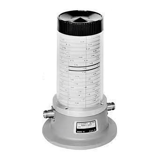
Overview Description The Keysight 537A coaxial frequency meter is used for measuring frequency in the 0.96 to 12.4 GHz range. Accuracy is obtained from the spiral scale. The meter contains a coaxial line coupled to a quarter- wavelength coaxial resonant cavity loaded with capacitance at the bottom of the band. -
Page 14: Measurement
The detector-indicator combination can be a thermistor mount and power meter such as the Keysight 478A and 432A, or a crystal detector and SWR meter. If a SWR meter is used as the indicator, the signal source must be modulated at 1000 Hz (sine or square wave modulation). For visual display, an oscilloscope can be used as the indicator. -
Page 15: Performance Test
P, T Sensitivity: <–7 dBm [a] P= performance tests, T = troubleshooting. Maintenance For dial-stop gear replacement, instrument recalibration, or any other repair needs, contact your local Keysight Technologies Sales and Service office for instructions and assistance. Keysight 537A Operating Note... -
Page 16: Return Loss Specifications
2, two detectors are connected together with a modulator, swept amplitude analyzer, and a dual directional coupler in a reflectometer test setup. The reflectometer is calibrated using a short. The 537A coaxial frequency meter under test is connected and the return measured. -
Page 17: Procedure
13 Disconnect the short from the reflectometer test port. 14 Connect the 537A under test to the reflectometer test port by disconnecting the short and inserting the properly terminated 537A under test. - Page 18 20.8 dB 27.8 dB 24.6 dB 21.9 dB 9.5 dB 11.0 dB 10.5 dB 9,8 dB 18 If the above limits are not met, test the 537A using a slotted line at the frequency in question. Keysight 537A Operating Note...
-
Page 19: Overall Accuracy
A sweep oscillator, 537A under test, detector, and oscilloscope are connected in series. The sweep oscillator is set to AF to sweep the band in question. The 537A is set to the frequency in question and the notch located on the trace. The sweep oscillator is set to CW and adjusted to the center of the absorption notch of the 537A. -
Page 20: Procedure
2 Set oscilloscope for a vertical sensitivity of about 02 V/cm (ac) and horizontal sensitivity of about 1 V/cm. 3 Set sweep oscillator for ^F automatic sweep of about 3.8 GHz + 12 MHz for 537A. 4 Set the 537A to 3.8 GHz. -
Page 21: Calibration Procedure
Figure 2 Figure 3 list procedures for checking instrument specifications. If dial accuracy is not within listed specifications, adjust 537A as detailed in the Calibration Alignment Procedure, as follows. 1 Remove knob (1). 2 Remove base (11) retaining screws. With base retaining screws removed, place the 537A in upright position and make electrical hookup for OVERALL ACCURACY TEST. - Page 22 Calibration Procedure THIS PAGE HAS BEEN INTENTIONALLY LEFT BLANK. Keysight 537A Operating Note...
- Page 23 This information is subject to change without notice. Always refer to the Keysight website for the latest revision. © Keysight Technologies 2014 - 2018 Edition 2, November 13, 2018 Printed in Malaysia *00536-90013* 00536-90013 www.keysight.com...
Need help?
Do you have a question about the 537A and is the answer not in the manual?
Questions and answers