Sign In
Upload
Manuals
Brands
Keysight Manuals
Measuring Instruments
53148A
Keysight 53148A Manuals
Manuals and User Guides for Keysight 53148A. We have
1
Keysight 53148A manual available for free PDF download: Operating And Programming Manual
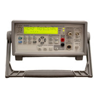
Keysight 53148A Operating And Programming Manual (311 pages)
Microwave Frequency Counter/Power Meter/DVM
Brand:
Keysight
| Category:
Measuring Instruments
| Size: 5.37 MB
Table of Contents
Serial Prefix Number
3
Certification and Warranty
3
Certification
3
Warranty
3
Safety Symbols
5
Safety Considerations
6
Acoustic Noise Emissions
7
Geräuschemission
7
Electrostatic Discharge Immunity Testing
7
Waste Electrical and Electronic Equipment (WEEE) Directive
8
Product Category
8
Sales and Technical Support
8
Table of Contents
9
List of Figures
17
List of Tables
19
In this Guide
21
Contents and Organization
22
Related Documents
23
Types of Service Available if Instrument Fails
24
Standard Repair Services (Worldwide)
24
Express Repair/Performance Calibration Service (USA Only)
24
Repair Instrument Yourself
24
Repackaging for Shipment
25
Description of the Microwave Frequency Counter/Power Meter/DVM
26
Options
27
Hardware
27
Retrofit
27
Accessories Supplied and Available
28
Accessories Supplied
28
Accessories Available
28
Manuals Supplied
28
Keysight 53147A/148A/149A Quick Reference Guide
29
Keysight 53147A/148A/149A Quick Reference Guide
30
1 Getting Started
31
The Front Panel at a Glance
32
The Front Panel Indicators at a Glance
33
The Front Panel Menus at a Glance
35
The Display Annunciators at a Glance
36
The Display Special Characters at a Glance
38
The Rear Panel at a Glance
39
Operating the Instrument
40
2 Operating Your Instrument
67
Introduction
68
Chapter Summary
68
How this Instrument Works for You
69
Summary of the Measurement Sequence
70
Using the Selection Keys
71
Sequencing through the Menu
71
Numeric Entry
72
Changing States
73
Using the Clear and Reset/Local Keys
75
Acknowledging Messages
75
Other Function Selection Keys
76
Measuring Frequency
80
Setting the Resolution and Measurement Rate
82
Setting the Resolution
82
Setting the Measurement Rate
84
Setting the Number of Averages
86
Averages Setting Example
86
Measuring Relative Frequency
89
Relative Frequency Example
89
Offsetting a Frequency Measurement
90
Frequency Offset Example
90
Measuring Power
93
Selecting a Power Head (Sensor)
93
Making a Power Measurement
93
Modifying and Adding Calibration Factor Tables
97
Table 2-1 Calibration Factor Data Point Modifications
98
Table 2-2 Calibration Table Data-Point Values
102
Measuring Relative Power
109
Relative Power Example
109
Offsetting a Power Measurement
110
Power Offset Example
110
Measuring Voltage
112
Voltage Measurement Example
112
Using the Menu
113
3 Programming
123
Introduction
125
Chapter Summary
126
How to Use this Chapter
128
New Users
128
Experienced Programmers
129
Applications
130
Assumptions
131
Related Documentation
132
Front Panel to SCPI Command Map
134
Figure 3-1 Front Panel Control to SCPI Command Map (Part 1 of 2)
135
Figure 3-1 Front Panel Control to SCPI Command Map (Part 2 of 2)
136
Figure 3-2 Front Panel Menu to SCPI Command Map (Part 1 of 2)
137
Figure 3-2 Front Panel Menu to SCPI Command Map (Part 2 of 2)
138
Command Summary
139
SCPI Conformance Information
139
IEEE 488.2 Common Commands
140
Table 3-1 IEEE 488.2 Common Commands
141
Keysight 53147A/148A/149A SCPI Subsystem Commands
142
Std/New Column
142
Parameter Form Column
142
Table 3-2 Keysight 53147A/148A/149A SCPI Command Summary
143
Table 3-2 Keysight 53147A/148A/149A SCPI Command Summary (Continued)
146
Table 3-2 Keysight 53147A/148A/149A SCPI Command Summary (Continued)
147
RST Response
149
Table 3-3 Keysight 53147A/148A/149A *RST State
149
Table 3-4 Unaffected by *RST
150
Programming the Instrument for Remote Operation
151
Connecting the Instrument to a Computer
152
Connecting with the GPIB
152
Figure 3-3 GPIB Interconnection
152
IEEE 488.1 Interface Capabilities
154
Connecting with the RS-232 Serial Interface
154
Figure 3-5 Wiring the RJ12/DB25 Adapter (1 of 2)
156
Figure 3-5 Wiring the RJ12/DB25 Adapter (2 of 2)
156
Figure 3-6 Assembling the Cable
157
Remote/Local Operation
158
Figure 3-7 RS-232 Serial Interconnection
158
Overview of Command Types and Formats
159
Common Command Format
159
SCPI Command and Query Format
159
Elements of SCPI Commands
160
Subsystem Command Syntax
160
Common Command Syntax
161
Abbreviated Commands
161
Keyword Separator
161
Figure 3-9 Simplified Common Command Syntax Diagram
161
Optional Keyword
162
Parameter Types
162
Parameter Separator
164
Query Parameters
164
Table 3-5 Command and Query Parameter Types
164
Suffixes
165
Table 3-6 Suffix Multipliers
165
Command Terminator
166
Using Multiple Commands
167
Program Messages
167
Program Message Syntax
167
Overview of Response Message Formats
169
Response Messages
169
Response Message Syntax
169
Response Message Data Types
170
Figure 3-11 Simplified Response Message Syntax Diagram
170
Table 3-7 Response Message Data Types
170
Status Reporting
173
Figure 3-12 53147A/148A/149A SCPI Status Reporting Summary Functional Diagram
174
Status Byte Register and Service Request Enable Register
175
Standard Event Status Register Group
178
The Operation and Questionable Data Status Register Groups
181
Programming the Instrument for Status Reporting
188
Determining the Condition of the Instrument
188
Resetting the Instrument and Clearing the Remote Interface -Example 1
188
Using the Standard Event Status Register to Trap an Incorrect Command-Example
189
Using the Operation Status Register to Alert the Computer When Measuring Is Complete-Example 3
189
Programming the Instrument to Display Results
193
Configuring the Instrument's Display
193
Commands for Displaying Results
194
Command for Displaying Raw Results
194
Commands for Displaying Relative Results
194
Commands for Enabling and Disabling the Display
194
Programming the Instrument to Synchronize Measurements
195
Synchronizing Measurement Completion
195
Resetting the Instrument and Clearing the Interface
195
Using the *WAI Command
196
Using the *OPC? Command
197
Using the *OPC Command to Assert SRQ
197
Writing SCPI Programs
199
Figure 3-17 SCPI Programming Flowchart
200
Programming Examples
201
Using BASIC
201
Using C
202
List of the Programming Examples
202
Making a Frequency Measurement (BASIC)
203
Making a Frequency Measurement (Quickbasic)
204
Making a Frequency Measurement (C)
205
Command Reference
207
Abort Command
208
Calibration Subsystem
209
Display Subsystem
214
Group Execute Trigger (GET)
216
Initiate Subsystem
217
Input Subsystem
219
Measure Subsystem
220
Measurement Instructions (:Configure, :Fetch, :Measure, :READ)
220
Descriptions of the Measurement Functions
226
How to Use the Measurement Instruction Commands
228
Memory Subsystem
230
[:Sense] Subsystem
232
[:Sense]:Function Subtree
237
[:Sense]:Power Subtree
239
[:Sense]:Roscillator Subtree
240
Status Subsystem
241
Status:operation Subtree
241
Status:questionable Subtree
245
Figure 3-19 the Questionable Data/Signal Status Register
245
System Subsystem
248
System:communicate Subtree
248
Trigger Subsystem
251
UNIT Subsystem
252
Common Commands
253
CLS (Clear Status Command)
253
DDT <Arbitrary Block> (Define Device Trigger Command) *DDT? (Define Device Trigger Query)
254
ESE (Standard Event Status Enable Command) *ESE? (Standard Event Status Enable Query)
254
ESR? (Event Status Register Query)
255
IDN? (Identification Query)
256
Figure 3-21 Standard Event Status Register
256
IST? (Instrument Status)
257
OPC (Operation Complete Command)
257
OPC? (Operation Complete Query)
258
PRE (Parallel Poll Enable Register) *PRE? (Parallel Poll Enable Register Query)
258
RCL (Recall Command)
259
RST (Reset Command)
259
SAV (Save Command)
260
SRE (Service Request Enable Command) *SRE? (Service Request Enable Query)
261
Figure 3-22 the Service Request Enable Register
261
STB? (Status Byte Query)
262
Figure 3-23 the Status Byte Register
262
TRG (Trigger Command)
263
TST? (Self-Test Query)
263
Table 3-15 Self-Test Error Values
264
WAI (Wait-To-Continue Command)
265
Errors
266
Reading an Error
266
Error Queue
267
Error Types
268
No Error
268
Command Error
268
Table 3-16 Error Types
268
Execution Error
269
Device-Specific or Instrument-Specific Error
269
Query Error
270
Error List
270
Table 3-17 Errors
271
4 Specifications
275
4 Specifications
276
Rack Mounting the Instrument
277
Messages
283
B Messages Overview
283
Overview
284
Status Messages
284
Status Messages
285
Self-Test Messages
286
Table B-2 Self-Test Messages
286
Error Messages
287
Table B-3 Error Messages
287
Using the Battery Option
289
Overview
290
Operating the Instrument from the Batteries
290
Operating the Instrument from a DC Power Source
292
Operating the Instrument from the Batteries
292
Replacing the Batteries
293
Removing the Batteries
293
Installing Batteries
294
Charging the Batteries
296
Precautions
297
Index
299
Advertisement
Advertisement
Related Products
Keysight 53147A
Keysight 53149A
Keysight 537A
Keysight HeNe 5519A
Keysight HeNe 5519B
Keysight 5500
Keysight 53230A
Keysight 53220A
Keysight 53210A
Keysight 1146B
Keysight Categories
Measuring Instruments
Test Equipment
Multimeter
Control Unit
Portable Generator
More Keysight Manuals
Login
Sign In
OR
Sign in with Facebook
Sign in with Google
Upload manual
Upload from disk
Upload from URL