Table of Contents
Advertisement
Quick Links
Advertisement
Table of Contents

Related Manuals for Leica TCS SP8 SMD


Summary of Contents for Leica TCS SP8 SMD
- Page 1 Living up to Life User Manual Leica TCS SP8 SMD for FCS, FLIM and FLCS...
- Page 2 This manual was created in cooperation with PicoQuant GmbH: Leica Microsystems CMS GmbH PicoQuant GmbH Am Friedensplatz 3 Rudower Chaussee 29 D-68165 Mannheim (Germany) 12489 Berlin (Germany) http://www.leica-microsystems.com http://www.picoquant.com http://www.confocal-microscopy.com Responsible for contents: Leica Microsystems CMS GmbH Copyright © Leica Microsystems CMS GmbH. All rights reserved.
-
Page 3: Copyright
Copyright Copyright All rights to this document are held by Leica Microsystems CMS GmbH. Adaptation, translation and reproduction of text or illustrations (in whole or in part) by print, photocopy, microfilm or other method (including electronic systems) is not allowed without express written permission from Leica Microsystems CMS GmbH. - Page 4 Copyright...
-
Page 5: Table Of Contents
TCS SP8 SMD System Components ........33... - Page 6 Leica APD Detector Unit ........
- Page 7 VIS/UV Lasers for TCS SP8 SMD........
- Page 8 Contents 11.4 Interlock Connectors ........... .72 11.4.1 Interlock Connector on the Supply Unit .
- Page 9 Contents 14.5.3 Selecting the Language for Online Help....... .113 14.5.4 Using Online Help.
- Page 10 Contents 16.2.4 Changing the Pulse Frequency for Pulsed Diode Lasers (405, 440, 470, 640 nm) ..........145 16.2.5 2-Laser PIE (405, 470, 640 nm) .
- Page 11 Contents 17.12.2 Running IRF Measurement ......... . .174 17.13 Remarks .
- Page 12 Contents 18.4 Measurements Step – FCS Measurement Time Series at Multiple Points ..201 18.4.1 FCS Network Connection ..........201 18.4.2 Definition of Multiple FCS Measuring Points in an Image or Stack.
- Page 13 Contents 26.4 Care ..............240 27 Repairs and Service Work.
- Page 14 Contents...
-
Page 15: About This User Manual
If you have any suggestions or improvements for this User Manual, please contact the Leica branch office in your country. -
Page 16: Additional Documentation
• Detection unit: This manual varies depending on the detection system. Here you can find basic information about alignment of the detection path and how to change filters. No separate manual is provided for the Leica APD detection unit. This detection unit is described in this User Manual in Chapter 9.4. -
Page 17: Intended Use
The manufacturer assumes no liability for damage caused by, or any risks arising from, use of the microscopes for purposes other than those for which they are intended, or not using the microscopes within the specifications of Leica Microsystems CMS GmbH. In such cases, the Declaration of Conformity shall be invalid. - Page 18 Intended Use...
-
Page 19: Liability And Warranty
Figures are for illustration purposes. The system you purchased can deviate from the illustrations without Leica Microsystems CMS GmbH explicitly specifying such. Leica Microsystems CMS GmbH shall not be liable for any injury or property damage caused by untrained or unauthorized persons. - Page 20 Liability and Warranty...
-
Page 21: Meaning Of The Warning Messages In The Manual
Meaning of the warning messages in the manual Meaning of the warning messages in the manual WARNING Electric shock This warns you of hazardous electrical voltage. Following the instructions is mandatory, since otherwise there is a risk of severe or fatal injury. - Page 22 Meaning of the warning messages in the manual CAUTION Injuries from… This note warns you of minor to moderate injuries that can be prevented by following instructions. NOTICE Risk of damage to the system This note describes possible material damage that can occur in case of misuse.
-
Page 23: General Safety Notes
Do not open these crates. The crates may be opened and unpacked by Leica service technicians or by people who are authorized by Leica Microsystems CMS GmbH only. • The system may only be set up by Leica service technicians or by people who are authorized by Leica Microsystems CMS GmbH. -
Page 24: Modifications To The System
General Safety Notes Modifications to the System • The system is installed by service technicians from Leica Microsystems CMS GmbH. You must not change the position of the system components. • The supply unit must always be set up and operated in an upright position. - Page 25 S70 microscope condenser could result in a hazard from laser radiation. • Only use S1 and S28 Leica microscope condensers. • Do not look into the eyepieces during the scanning operation. • Never change samples during a scanning operation.
-
Page 26: Electrical Safety
• Before any cleaning or servicing, de-energize the entire system. To do so, use the power switches of all components and disconnect all power cables from the power supply. • Only use the power cable included or provided by your local Leica service technicians for connecting individual peripheral devices to the power supply. - Page 27 General Safety Notes If any of these occur, immediately notify the Leica branch office in your country or your local contact person.
- Page 28 General Safety Notes...
-
Page 29: Additional Notes On Handling The System
• We recommend using a room that can be completely darkened. • Do not expose the system to drafts. • If the system has to be moved to a new location for any reason, contact the Leica branch office in your country. -
Page 30: Protecting The System
Additional Notes on Handling the System • Do not switch the workstation off after a software crash, but restart the LAS AF software after 15 seconds. No image data are lost in case of a software crash. If the LAS AF software is restarted without restarting the workstation, the data are automatically restored. -
Page 31: Objectives
Additional Notes on Handling the System excitation etc. • If you have any further questions, please directly contact the Leica branch office in your country (see Chapter "Contact"). 6.3.1 Objectives • Only use immersion fluids that are intended for the objective. Unsuitable immersion fluid can contaminate or destroy the objective. - Page 32 Additional Notes on Handling the System...
-
Page 33: System Overview And Properties
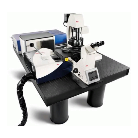
TCS SP8 SMD System Variants 7.1.1 TCS SP8 SMD System Components Figure 2: System components using the TCS SP8 SMD with upright microscope and flexible supply unit as an example 1 Trolley with external lasers, detectors and 8 TCS SP8 workstation... -
Page 34: Tcs Sp8 Smd With Upright Microscope
System Overview and Properties 7.1.2 TCS SP8 SMD with Upright Microscope Figure 3: Dimensions of TCS SP8 SMD with upright microscope and flexible supply unit 7.1.3 TCS SP8 SMD with Inverted Microscope Figure 4: TCS SP8 SMD dimensions with inverted microscope and flexible supply unit... -
Page 35: Tcs Sp8 Smd System Variants With White Light Laser
7.2.1 TCS SP8 SMD System Components with White Light Laser Figure 5: System components using the TCS SP8 SMD with white light laser, upright microscope and PicoQuant laser as an example 1 Trolley with external lasers, detectors and 8 TCS SP8 workstation... -
Page 36: Tcs Sp8 Smd With White Light Laser And Upright Microscope
TCS SP8 SMD with White Light Laser and Upright Microscope Figure 6: Dimensions of TCS SP8 SMD with white light laser, upright microscope, and PicoQuant laser Figure 7: Dimensions of TCS SP8 SMD with white light laser and upright microscope, without PicoQuant... -
Page 37: Tcs Sp8 Smd With White Light Laser And Inverted Microscope
TCS SP8 SMD with White Light Laser and Inverted Microscope Figure 8: Dimensions of TCS SP8 SMD with white light laser, inverted microscope and PicoQuant laser Figure 9: Dimensions of TCS SP8 SMD with white light laser and inverted microscope, without... -
Page 38: Tcs Sp8 Smd System Variants With Mp Configuration
The system is available with an infrared laser as well. Here, you see the example dimensions for the MP variant with 150 x 120 cm (4'11" x 3'11") optical table. If you should need the dimensions for using a larger table or additional accessories, please look at the Leica TCS SP8 MP Room Requirements. - Page 39 System Overview and Properties Figure 11: System overview of TCS SP8 SMD with MP configuration and white light laser, without PicoQuant laser; upright and inverted microscope possible 1 Trolley with detectors, their controllers and 5 Optical table, 150 x 120 cm (4 "...
-
Page 40: Controls On The Supply Unit
System Overview and Properties Controls on the Supply Unit 7.4.1 Main Switch Board on the Flexible Supply Unit Figure 13: Overview of the main switch board on the flexible supply unit 7.4.2 Control Panel Field on the Compact Supply Unit (Only for FLIM) Figure 14: Overview of the control panel field on the Compact supply unit... -
Page 41: Technical Data
System Overview and Properties Technical Data 7.5.1 Dimensions Dimensions of the system (length x depth x height) TCS SMD for TCS SP8 with upright 350 x 120 x 175 cm (11'6" x 3'11" x 5'9") microscope, compact and flexible supply unit possible TCS SMD for TCS SP8 with inverted 364 x 120 x 150 cm (11'11"... -
Page 42: Electrical Specifications
System Overview and Properties 7.5.3 Electrical Specifications Flexible supply unit Compact supply unit White light laser Supply voltage 100 V~ to 240 V~ ± 10%, grounded Power consumption 2x 1600 VA 700 VA 400 VA (Including peripheral devices connected to the flexible supply unit's multiple socket outlet, see Chapter 8.5) -
Page 43: Serial Number
System Overview and Properties Serial Number The serial number for your system is located on the rear side of the scan head: Figure 15: Rear side of the scan head – label with serial number... - Page 44 System Overview and Properties...
-
Page 45: Ambient Conditions
Otherwise, this could cause fire and electrical shocks to the system and the electrical components. • The room should be equipped with a telephone connection to contact Leica Microsystems CMS GmbH for phone support. For RemoteCare, an Internet connection is also needed. -
Page 46: Room Dimensions
PicoQuant laser TCS SP8 SMD with MP configuration 610 x 290 cm (20' x 9'6") TCS SP8 SMD with white light laser and 610 x 290 cm (20' x 9'6") MP configuration, without PicoQuant laser TCS SP8 SMD with white light laser, MP 660 x 290 cm (21'8"... -
Page 47: Electrical Connection Requirements
Ambient Conditions Electrical Connection Requirements WARNING Electric shock is possible when using ungrounded sockets This system is designed for connection to grounded (earthed) outlets. The grounding plug performs an important safety function. To avoid the risk of electrical shock or damage to the instrument, do not disable this feature. -
Page 48: System With Compact Supply Unit (Only With Flim)
Ambient Conditions 8.4.2 System with Compact Supply Unit (Only with FLIM) Supply voltage 100 V~ to 240 V~ ± 10%, grounded Frequency 50/60 Hz Power connection Two separate electric circuits with Power supply voltage: 100 V - 120 V, fuse protection: 20 A Power supply voltage: 200 V - 240 V, fuse protection: 12 - 16 A (One for the compact supply unit's power supply and one for supplying peripheral devices) -
Page 49: Load Capacity Of The Multiple Socket Outlet On The Flexible Supply Unit
Ambient Conditions Load capacity of the multiple socket outlet on the flexible supply unit The total power consumption of all loads connected to the multiple socket outlet (see Figure 16) must not exceed 800 VA. The terminals are intended for: •... -
Page 50: System With Flexible Supply Unit
Ambient Conditions 8.6.1 System with Flexible Supply Unit Waste heat of the complete Max. of 3.9 kW (VIS system with SMD components) system, including the argon Max. of 6.9 kW (MP system with SMD components) laser Max. 4.3 kW (WLL and VIS system with SMD components) Max. -
Page 51: Smd Components
The TCS SMD system combines technologies for individual molecule detection and analysis (SMD = Single Molecule Detection analysis), such as FCS/FCCS, FLIM, FLCS, etc., with confocal imaging. It is a bundle of a confocal or multiphoton microscope from Leica Microsystems CMS GmbH and SMD equipment from PicoQuant GmbH (PQ). The SMD... -
Page 52: Flim Application Area
FLIM excitation: HyD RLD Counting unit TCSPC unit PH300 + with multiple detectors: Router PHR800 Table 4: Special SMD hardware for FLIM 9.1.2.2 Software License Leica LAS AF SMD FLIM Wizard PQ SPT SPT2 Table 5: Software license for FLIM... -
Page 53: Application Area Fcs/Fccs, Flim, Flcs, Gated Fcs
TCSPC unit PH300 + Router PHR800 Table 6: Special SMD hardware for FCS/FCCS, FLIM, FLCS, gated FCS 9.1.3.2 Software License Leica LAS AF FCS Wizard + FLIM Wizard PQ SPT SPT1+2 Table 7: Software license for FCS/FCCS, FLIM, FLCS, gated FCS... -
Page 54: Detection Units From Picoquant
SMD Components Figure 17: SP8 scan head with APD detection at the external X1 port Detection Units from PicoQuant The following detection units are available for SMD upgrades: Figure 18: Single-channel PMT detection unit Figure 19: Double-channel PMT detection unit... -
Page 55: Leica Apd Detector Unit
APDs. Leica APD Detector Unit Two APDs (of type AQR from Perkin Elmer) are located in the Leica APD detector unit (Figure 22). They are linked to the X1 port adapter on the scan head using optical fibers. At the APD detector unit, the APDs can be switched on independently of one another (Figure 22, item 1 and 2). -
Page 56: General Precautionary Measures For Using Apd Detector Units
• Never switch the APDs on with a light source switched on. To prevent inadvertent illumination of the APDs, in the Leica LASAF software, place the external port (X1 Port) in Beam Path Settings in the LAS AF software in the mirror position (see Chapter 16.1.1 and Chapter 18.2.1) before you switch on the APDs. -
Page 57: Laser Coupling Unit (Lcu)
SMD Components Figure 23: Front side of the trigger unit Figure 24: Rear side of the trigger unit Laser Coupling Unit (LCU) WARNING Risk of permanent eye and skin damage from laser radiation The laser coupling unit must not be opened. The adjustment of the laser beam and the coupling must be carried out by a service technician. -
Page 58: Attenuation Unit
SMD Components 9.6.1 Attenuation Unit The laser coupling module contains an attenuation unit which enables a graduated and continuous intensity attenuation via two different elements: a filter wheel and a scaffold (Figure 26). Using the filter wheel, the attenuation is adjustable in three steps (between four positions) by replacing the filter in the beam paths: •... -
Page 59: Other Picoquant Components
SMD Components 9.6.2 Other PicoQuant Components Figure 27: PicoHarp 300 TCSPC unit Figure 28: Router PHR 800. A multi-photomultiplier configuration is shown here. Figure 29: Laser drivers for pulsed diode lasers: PDL 828 Sepia II Figure 30: Laser drivers for pulsed diode lasers: PDL 800-B... - Page 60 SMD Components Figure 31: DSN 102 Dual SPAD Power Supply...
-
Page 61: Laser
System variant Usable Wavelength range laser class lasers 400 - 700 nm (visible laser radiation) TCS SP8 SMD 3B / IIIb 350 - 400 nm (invisible laser radiation) 400 - 700 nm (visible laser radiation) TCS SP8 SMD 3B / IIIb... -
Page 62: Vis/Uv Lasers For Tcs Sp8 X
Laser OPSL 514 Continuous wave (cw) OPSL 552 Continuous wave (cw) DPSS 561 < 100 < 12 Continuous wave (cw) HeNe < 4 < 1 Continuous wave (cw) HeNe < 15 < 5 Continuous wave (cw) Diode 638 Continuous wave (cw) 10.2.2 VIS/UV Lasers for TCS SP8 X... -
Page 63: Femtosecond Laser
< 0,8 pulsed > 100 fs 10.3 Overview of Usable Lasers for FCS 10.3.1 VIS/UV Lasers for TCS SP8 SMD The TCS SP8 SMD (for FCS) features a combination of the lasers listed below: Laser type Wavelength Maximum Maximum Pulse duration... -
Page 64: Overview Of Usable Lasers For Flim
Pulsed 10.4.2 Infrared Lasers for TCS SP8 SMD with MP Configuration The TCS SP8 SMD with MP configuration (for FLIM) can contain a combination of all the infrared lasers in Chapter 10.4.1 and the following infrared lasers: 10.4.2.1 Picosecond laser... - Page 65 Laser Chameleon 680 - 1080 < 4,0 < 1,9 pulsed ~ 140 fs Vision II Chameleon 690 - 1050 < 3,5 < 1,9 pulsed ~ 75 fs Vision S Chameleon Ultra II 680 - 1080 < 4,0 < 1,9 pulsed ~ 140 fs Compact OPO 1000 - 1300 <...
-
Page 66: Overview Of Usable Lasers For Flcs
Laser 10.5 Overview of Usable Lasers for FLCS 10.5.1 VIS/UV Lasers for TCS SP8 SMD The TCS SP8 SMD (for FLCS) features a combination of the lasers listed below: Laser type Wavelength Maximum Maximum Pulse duration (nm) light output at... -
Page 67: Safety Features
Safety Features Safety Features The Leica TCS SP8 SMD system is available with a flexible or a compact supply unit (only for FLIM). Note the safety features described here that apply to your supply unit. 11.1 Main Circuit Breaker for Disconnecting the Power Supply 11.1.1... -
Page 68: Other Components
Safety Features 11.1.3 Other Components Observe the user manuals for other components You can find information on the network equipment for additional components from the respective documents provided by the manufacturer. 11.2 Key Switch 11.2.1 Master Key Switch on the Compact Supply Unit There is a master key switch on the compact supply unit for protection against unauthorized use of the laser products. -
Page 69: Key Switch For The White Light Laser
Safety Features Figure 34: Master key switch on the main switch board of the flexible supply unit 11.2.3 Key Switch for the White Light Laser The external lasers can also be turned off individually. The detachable key switch for protection against unauthorized use of the external white light laser is located on the front of the white light laser (see Figure 35). -
Page 70: Key Switches For Other External Lasers
Safety Features Figure 37: Key switch on external UV laser 405 11.2.5 Key Switches for Other External Lasers Observe the user manuals for external lasers Please refer to the information from the documents provided by the laser manufacturer for the external lasers. Pay particular attention to the laser manufacturer's notes! 11.3 Emission Warning Indicators... -
Page 71: Emission Warning Indicator On The White Light Laser
Safety Features Figure 39: Emission warning indicator on the main switch board of the flexible supply unit 11.3.2 Emission Warning Indicator on the White Light Laser The emission warning indicator of the achromatic light laser is located on the front of the achromatic light laser (see Figure 40) and is red when lit. -
Page 72: Emission Warning Indicator On Other External Lasers
• Scanning of the specimen is not activated after being switched on properly (laser radiation in the specimen area). If any of these occur, immediately notify the Leica branch office in your country or your local contact person. 11.4 Interlock Connectors 11.4.1... - Page 73 Safety Features The total length of the cable must not exceed 10 m. If a large amount of electromagnetic interference (EMC) is expected in the environment, use a shielded cable with a shielded plug. Figure 43: Interlock connector on the compact supply unit Figure 44: Interlock connector on the rear side of the flexible supply unit...
-
Page 74: Interlock Connector On The White Light Laser
Safety Features 11.4.2 Interlock Connector on the White Light Laser The interlock connector is located on the rear side of the white light laser (12 V DC operating voltage, see Figure 45). Figure 45: Interlock Connector on the White Light Laser Interlock connector when using the white light laser If the white light laser is operated as a component of the TCS SP8 X system, you have to use the interlock connector on the supply unit! The... -
Page 75: Interlock Connector On The Scan Head
Safety Features 11.4.4 Interlock Connector on the Scan Head The interlock connector is located on the rear side of the scan head (operating voltage: 12 V DC, see Figure 46). For laser safety reasons, the inverted microscope must be connected to this connection or, if an upright microscope is used, to the mirror housing. -
Page 76: Safety Switches On The Microscope
LAS AF. For safety reasons, the shutters remain closed. No further use of the laser is possible. In this situation, the system must not be operated. Contact the Leica branch office in your country or your contact person. - Page 77 For safety reasons, the shutters remain closed. No further use of the laser is possible. In this situation, the system must not be operated. Contact the Leica branch office in your country or your contact person.
-
Page 78: Special Laser Safety Equipment
Safety Features 11.7 Special Laser Safety Equipment 11.7.1 Laser Protection Tube and Laser Protection Shield The laser protection tube and the laser protection shield are used in inverted microscopes for protection from laser radiation (see Figure 48). Figure 48: Inverted microscope 1 Laser Protection Tube 2 Condenser Base 3 Laser Protection Shield... -
Page 79: Safety Beam Guide On The Mp System
Safety Features 11.7.2 Safety Beam Guide on the MP System The light of all employed VIS lasers (wavelength range 400 - 700 nm, visible spectrum) and UV lasers (wavelength range < 400 nm, invisible) is fed through a fiber optic cable and, therefore, completely shielded until it leaves the microscope objective and reaches the specimen. - Page 80 Safety Features...
-
Page 81: Safety Labels On The System
Missing or damaged safety labels must be attached immediately and at the described location. Operation without the safety labels shown is not permitted. If you have any further questions, contact your laser safety officer or the Leica branch office in your country immediately. 12.1 Compact Supply Unit (Only for FLIM) -
Page 82: Flexible Supply Unit
Safety Labels on the System 12.2 Flexible Supply Unit Figure 51: Safety labels on the flexible supply unit Position Safety label in English Translation of the safety label DANGER VORSICHT LASER RADIATION CLASS 3B LASERSTRAHLUNG KLASSE 3B WHEN OPEN AVOID EXPOSURE TO WENN ABDECKUNG GEÖFFNET NICHT BEAM DEM STRAHL AUSSETZEN... -
Page 83: Inverted Microscope
Safety Labels on the System 12.3 Inverted Microscope Figure 52: Safety labels for the inverted microscope Position System Safety label in English Translation of the safety label LASER RADIATION IS EMITTED AUSTRITT VON FROM THIS APERTURE LASERSTRAHLUNG AVOID EXPOSURE BESTRAHLUNG VERMEIDEN UV/MP VISIBLE AND INVISIBLE LASER AUSTRITT VON SICHTBARER... -
Page 84: Upright Microscope
Safety Labels on the System 12.4 Upright Microscope Figure 53: Safety labels for the upright microscope Position System Safety label in English Translation of the safety label DANGER VORSICHT LASER RADIATION CLASS 3B LASERSTRAHLUNG KLASSE 3B WHEN OPEN AVOID EXPOSURE WENN ABDECKUNG GEÖFFNET TO BEAM NICHT DEM STRAHL AUSSETZEN... -
Page 85: Mirror Housing
Safety Labels on the System 12.5 Mirror Housing Figure 54: Safety label on the mirror housing (top) Position System Safety label in English Translation of the safety label DANGER VORSICHT LASER RADIATION CLASS 3B LASERSTRAHLUNG KLASSE 3B WHEN OPEN AVOID EXPOSURE WENN ABDECKUNG GEÖFFNET TO BEAM NICHT DEM STRAHL AUSSETZEN... -
Page 86: Cover For Replacement Flange
Safety Labels on the System 12.6 Cover for Replacement Flange Front view of the cover: Figure 55: Safety labels on the cover Position System Safety label in English Translation of the safety label DANGER VORSICHT LASER RADIATION CLASS 3B LASERSTRAHLUNG KLASSE 3B WHEN OPEN AVOID EXPOSURE WENN ABDECKUNG GEÖFFNET TO BEAM... -
Page 87: Transmitted Light Detector (Tld)/Reflected Light Detector (Rld)
Safety Labels on the System 12.7 Transmitted Light Detector (TLD)/Reflected Light Detector (RLD) Figure 56: Safety labels on the transmitted light detector or reflection detector with MP systems Position Safety label in English Translation of the safety label DANGER VORSICHT VISIBLE AND INVISIBLE LASER SICHTBARE UND UNSICHTBARE RADIATION CLASS 4... - Page 88 Safety Labels on the System Position System Safety label in English Translation of the safety label DANGER VORSICHT LASER RADIATION CLASS 3B LASERSTRAHLUNG KLASSE 3B WHEN OPEN AVOID EXPOSURE WENN ABDECKUNG GEÖFFNET TO BEAM NICHT DEM STRAHL AUSSETZEN DANGER VORSICHT VISIBLE AND INVISIBLE LASER SICHTBARE UND UNSICHTBARE RADIATION CLASS 3B...
-
Page 89: White Light Laser
Safety Labels on the System 12.9 White Light Laser Rear side of white light laser: Figure 58: Safety labels on the rear side of the white light laser Position Safety label in English Translation of the safety label DANGER VORSICHT LASER RADIATION CLASS 3B LASERSTRAHLUNG KLASSE 3B WHEN OPEN AVOID EXPOSURE TO... -
Page 90: Mp Beam Coupling Unit
Safety Labels on the System 12.11 MP Beam Coupling Unit Figure 60: Safety label for the MP beam coupling unit (top side) Position Safety label in English Translation of the safety label DANGER VORSICHT VISIBLE AND INVISIBLE LASER SICHTBARE UND UNSICHTBARE RADIATION CLASS 4 LASERSTRAHLUNG KLASSE 4 WHEN OPEN AVOID EYE OR SKIN... -
Page 91: Switching On The System
Switching On the System Switching On the System The TCS SP8 SMD is available in different versions. You must precisely follow the switch-on sequence that applies to your system variant. During FLIM experiments, it is also possible to operate the system with a compact supply unit. - Page 92 Switching On the System Figure 62: Overview of the main switch board on the flexible supply unit 4. Switch off the multiple socket outlet on the trolley. Switch on the SMD workstation if it does not start up automatically. 5. Check whether the microscope is switched on. The microscope is operational once the readiness indicator (Figure 63, item 1) on the toggle switch is lit up.
- Page 93 Switching On the System 7. Switch on the scan head on the flexible supply unit's main switch board (see Figure 62, item 2). 8. Switch on the lasers on the main switch board of the flexible supply unit (see Figure 62, item 3).
- Page 94 Switching On the System Figure 66: Key Switch for the White Light Laser White Light Laser Error Messages An error report appears in the display of the white light laser. • if the room temperature exceeds 40°C -> the white light laser switches itself off and can only be turned back on after the room cools off.
- Page 95 Switching On the System Figure 69: Key switch on the power supply of external UV laser 355 Figure 70: Key switch on external UV laser 405 15. After the workstation has started, log on to the operating system. Using a personalized user ID Use your personal user ID if one has been set up.
-
Page 96: Confocal System With Compact Supply Unit (Only With Flim)
Switching On the System 13.2 Confocal System with Compact Supply Unit (Only with FLIM) 1. If you are using a fluorescence lamp EL6000, switch it on first. Figure 71: EL6000 2. If you are using a HyD RLD, switch it on at its supply unit. You can find additional information on the HyD RLD in Chapter 13.3. - Page 97 Switching On the System Figure 73: Microscope electronics box 6. If your system has an infrared laser (MP) or an optical parametric oscillator (OPO), switch on the NDD detection unit: Figure 74: Switch on the NDD detection unit 7. Switch on the scan head on the front side of the compact supply unit (see Figure 75, item 1).
- Page 98 Switching On the System 10. To switch on the laser in the supply unit, press the key switch on the front side of the compact supply unit (see Figure 75, item 3). WARNING Risk of permanent eye and skin damage from laser radiation From this time on, laser radiation may be present in the specimen area of the laser scanning microscope.
-
Page 99: Hyd Reflected Light Detectors (Hyd Rlds)
Switching On the System Figure 79: Key switch on external UV laser 405 13. After the workstation has started, log on to the operating system. Using a personalized user ID Use your personal user ID if one has been set up. This ensures that user- specific settings are saved and maintained for this user only. -
Page 100: Starting The Smd Hardware And Software
The target region for FLIM or FCS measurements has already been determined (Chapter 15, Chapter 18.1.5, Chapter 18.1.6 and Chapter 18.2). The SMD upgrade can be started completely independently from the Leica TCS SP8. Start the SMD upgrade hardware and software in the following sequence: 1. - Page 101 6. Set the correct fluorescence filter on the corresponding filter holder position of the external PicoQuant detector unit or on the Leica TCS SP8. Select the correct SMD filter cube in the X1 port adapter (Chapter 23, Figure 188). If you have a dual-channel APD detector unit, set the variable beam splitter unit to the correct position (see dual channel detector unit manual for details).
- Page 102 Switching On the System...
-
Page 103: Las Af
Image acquisition, image analysis and image processing are carried out using LAS AF. Within the Leica LAS AF software, FCS and FLIM experiments are designed and executed using special Wizards. After data acquisition, the SMD data analysis is carried out within the SymPhoTime (SPT) software by PicoQuant. -
Page 104: Structure Of The Graphical User Interface
LAS AF You are now in the main LAS AF view. 14.2 Structure of the Graphical User Interface Figure 83: Structure of the Graphical User Interface 1 Scaling range 7 Image display 2 Operating mode selection 7a Image display settings 3 Steps 7b Image processing and image analysis options 4 Menu... - Page 105 LAS AF The displayed tabs depend on the selected step. In the TCS SP8's basic operating mode, the following tabs are assigned to the steps: • Acquire step: Experiments tab: Directory tree for opened files Acquisition tab: Hardware settings for the current experiment and parameter settings for image acquisition •...
- Page 106 LAS AF select how the acquisition is to be started: • Autofocus: Focusing using the selected settings • Live: Acquisition of a live image • Capture Image: Acquisition of an individual image • Start: Series of acquisitions using the selected settings The software's "experiment concept"...
-
Page 107: Design Of The Flim Wizard In Las Af
LAS AF 14.3 Design of the FLIM Wizard in LAS AF The LAS AF software includes a FLIM wizard with operating steps for capturing and optimizing image data as well as a function that enables FLIM measurements to be carried out. - Page 108 LAS AF Figure 87: Overview of the FLIM Wizard steps • "Setup Corr-ring" step Some immersion objectives have a correction ring to optimally correct for differences in the refractive index between immersion and specimen and temperature effects. An optimum adjustment of the correction ring correlates with the best possible optical resolution of the system.
- Page 109 LAS AF In each step, two to three different tabs are shown in the tab area: • On the Experiments tab, the intensity image data shown on the image display (LAS AF Viewer) is saved. The FLIM data is only saved in the PicoQuant software SymPhoTime. •...
-
Page 110: Design Of The Fcs Wizard In Las Af
LAS AF 14.4 Design of the FCS Wizard in LAS AF The LAS AF software includes an FCS Wizard with steps for capturing and optimizing image data as well as a function that enables FCS measurements to be carried out on previously defined points. - Page 111 LAS AF Figure 90: Overview of the SMD FCS Wizard steps • "Setup Corr-ring" step The recommended FCS objective (63x Plan Apo 1.2 W) has a correction ring to optimally correct for differences in the refractive index between immersion and specimen and temperature effects. An optimum adjustment of the correction ring correlates with the best possible optical resolution of the system –...
- Page 112 LAS AF • Step Measurements: Here, you can define multiple FCS measuring points in the previously acquired xy or xz image or xyz or xzy stack, then carry out consecutive and automatic FCS measurements defined in the Setup FCS step. The list of measuring points can be saved and reloaded.
-
Page 113: Las Af Online Help
LAS AF 14.5 LAS AF Online Help 14.5.1 Structure of Online Help Online Help is divided into seven main chapters: • General Information: Contains legal notices and general information on LAS AF. • About LAS AF Online Help: Contains general information for the LAS AF Online Help. •... -
Page 114: Using Online Help
LAS AF 1. In LAS AF, switch to the Configuration step. 2. Click on the User Config button on the left side to access the User Configuration dialog. 3. In the User Configuration dialog, select the desired language under Help Language. Figure 93: Selecting the language for Online Help The next time you call up Online Help, the help topics will be displayed in the selected... -
Page 115: Full-Text Search With Logically Connected Search Terms
LAS AF 14.5.5 Full-text Search with Logically Connected Search Terms In Online Help, you can use the full-text search function to search for words and for phrases enclosed in quotation marks. You can also use placeholders when searching (such as * or You can run a full-text search using logical operators (such as boolean operators) in order to link search terms and thereby increase the accuracy of search results. - Page 116 LAS AF...
-
Page 117: Selecting The Laser
Selecting the Laser Selecting the Laser 15.1 Activate laser as the excitation source in the configuration menu All available lasers can be used for images of normal image intensity. The lasers are switched on outside the Wizards in the TCS SP8 operating mode. 1. -
Page 118: Using Continuous Wave Vis Lasers
Selecting the Laser Figure 96: Activate laser in the LAS AF laser configuration window 15.1.1 Using Continuous Wave VIS Lasers 1. Open the laser shutter in Beam Path Settings (Figure 97, item 1). 2. Set the desired laser line intensity using the slider (Figure 97, item 2). Open shutter The red-colored ON button (Figure 97, item 1) signals that the shutter is open. -
Page 119: Using Mp Lasers
Selecting the Laser Figure 98: Beam Path Settings: MFP setting (1) and selection of AOBS (2) 4. With beam splitter systems, set the beam splitter to one which corresponds to the continuous wave laser line selected for the scan head. 5. - Page 120 Selecting the Laser Figure 100: MP Laser Configuration, second shutter closed Figure 101: MP Laser Configuration, second shutter opening WARNING Risk of permanent eye damage from laser radiation The red button signals that the shutter is open and laser radiation can escape.
-
Page 121: Using Pulsed Vis Lasers
Selecting the Laser Figure 102: MP Laser Configuration, second shutter open 3. You can now set the wavelength of the MP laser. Use either the slider (Figure 102, item 3) or enter the desired wavelength directly. 4. Select a suitable neutral filter strength for the light incidence (Trans) and/or define the Gain and Offset from the EOM (Figure 99, item 3). - Page 122 Selecting the Laser Notes about laser intensity For intensities under 3.5 (PDL) or 35 % (SEPIA II), the pulsed output of the laser light can be interrupted. Do not select too high of values on the laser driver (PDL or SEPIA) unless the laser intensity is not sufficient.
- Page 123 Selecting the Laser Configuration Lasers used MFP settings in LAS AF Substrate 405+440 Substrate RSP 445 405+470 Substrate 405+470 SD 470 SD 470 405+470+640 Substrate 405+470 DD 470+640 405+640 DD 470+640 DD 470+640 470+640 DD 470+640 DD 470+640 RSP 445 440+470 RSP 445 SD 470...
-
Page 124: Using Pulsed Uv Lasers
Selecting the Laser 15.1.4 Using Pulsed UV Lasers 1. Open the shutter for pulsed lasers. 2. Activate the 405 nm laser by moving the corresponding slider upwards (Figure 106, item 1). Figure 106: Settings for the UV lasers in Beam Path Settings 3. - Page 125 Selecting the Laser 3. You can activate up to eight laser lines simultaneously. Click the corresponding buttons (Figure 108, item 2). The position of the laser lines in the spectrum can be moved as desired. 4. Adjust the power of the line by adjusting the slider for the respective laser line. 5.
- Page 126 Selecting the Laser Automatic MFP positioning Within the FLIM Wizard, the MFP positioning is done automatically. MFP positioning occurs at the corresponding beam splitters whenever a laser selection is changed. Outside of the wizard, the user must configure this setting on his or her own. Settings made automatically can be modified later by the user.
-
Page 127: Flim Data Acquisition
FLIM Data Acquisition FLIM Data Acquisition You can acquire a FLIM image using a pulsed laser, an internal or external FLIM detector, and an external PicoQuant TCSPC unit. 16.1 Setup Imaging Step – Image Acquisition 1. Start the FLIM Wizard in LAS AF. To do so, open the operating mode selector and select FLIM (Figure 110). - Page 128 FLIM Data Acquisition Figure 111: Selecting the Mirror setting for X1 Port 2. In Beam Path Settings, enable the desired photomultiplier by clicking the corresponding button (Figure 112, item 1). 3. When a detector is activated, it can be recognized by a shadow with a slider below the electromagnetic spectrum.
-
Page 129: External Apds
FLIM Data Acquisition Figure 114: Beam Path Settings of LAS AF when using detectors for default image acquisition (1) and internal FLIM detectors for intensity image acquisition (2) 6. Acquire an image by clicking the Capture Image image acquisition button or acquire a stack by clicking the Start image acquisition button. -
Page 130: External Flim Photomultiplier
FLIM Data Acquisition 3. Deactivate all PMTs. 4. Activate the APDs by clicking the corresponding buttons (Figure 115, item 2). Dependency of the spectral detection range of the APDs The spectral detection range of the APDs is determined by the SMD filter cube used, not by the slider settings for the photomultipliers. -
Page 131: Using Mp Lasers
FLIM Data Acquisition Figure 116: Dialog for AOBS configuration 2. Choose a suitable laser line and adjust the intensity to the desired level using the AOTF slider. 3. If the system has a multifunction port (MFP), set it to Substrate. 16.1.2.2 Using MP Lasers Prevent light incidence during MP FLIM measurement... -
Page 132: Using Pulsed Uv Lasers
FLIM Data Acquisition Figure 117: Settings for using pulsed VIS lasers as excitation source 4. Check whether the correct beam splitter (MFP) is selected (Table 18). You can use the pulsed VIS lasers together with the pulsed UV laser (405 nm). The MFP setting is not influenced by the UV laser. -
Page 133: Using White Light Lasers
FLIM Data Acquisition 16.1.2.5 Using White Light Lasers 1. Select the desired laser lines in the Whitelight dialog in Beam Path Settings. 2. Make sure that the AOBS is at fluorescence. 3. Set the desired intensity using the AOTF slider. 4. -
Page 134: Setup Flim Step - Optimizing The Flim Measurement Conditions
FLIM Data Acquisition 16.2 Setup FLIM Step – Optimizing the FLIM Measurement Conditions Go to the Setup FLIM step in the FLIM Wizard. Now set the instrument parameters for a FLIM measurement. 16.2.1 Selecting FLIM Detectors For FLIM measurements, special detectors have to be used that are able to do single photon counting with a high time resolution. -
Page 135: Flim Data Acquisition With Internal Sp Flim Detectors
FLIM Data Acquisition Whenever you toggle between these options, the split-off filter on the stand and the X1 port are automatically moved to the correct position and the corresponding detectors are activated. If there are pulsed diode lasers in your system, this selection also impacts the automatic adjustment of the fluorifier disc (if present), according to Table 19, page 143. -
Page 136: Flim Data Acquisition With External Mpd Apds
FLIM Data Acquisition acquisition is applied to the detectors. In other words, the gain cannot be changed as long as FLIM is selected. 3. Select a suitable range for spectral detection by adjusting the spectral sliders of the SP FLIM detectors accordingly (Figure 120, item 2 and 3). At the same time, additional detectors can be activated and used for intensity image acquisition. -
Page 137: Flim Data Acquisition With External Photomultiplier
FLIM Data Acquisition Figure 121: Selecting external APDs for FLIM data acquisition 5. If the APDs still have not been activated in Beam Path Settings, click the buttons allocated to the APDs and set them to ON. Dependency of the spectral detection range of the APDs The spectral detection range of the APDs is determined by the SMD filter cube used, not by the slider settings for the photomultipliers. -
Page 138: Flim Data Acquisition With Detectors At Ndd Position (Hyd Rld)
FLIM Data Acquisition cube and mount it in the X1 port adapter (Chapter 23). In LAS AF, a simulator photomultiplier is activated. This means that no image from the external photomultiplier will be displayed in LAS AF. Dependency of the spectral detection range of the photomultiplier The spectral detection range of the photomultiplier is determined by the SMD filter cube used, not by the slider settings for the photomultipliers. - Page 139 FLIM Data Acquisition Figure 122: Selecting external HyD RLD for FLIM data acquisition Dependency of the spectral detection range of the HyD RLD The spectral detection range of the HyD RLD is determined by the NDD filter cube used, not by the slider settings for the photomultipliers. 5.
-
Page 140: Selecting Laser Lines For Flim
FLIM Data Acquisition Cooling of HyD RLDs: To achieve the minimum dark count rate and thereby optimum performance, the HyD RLDs are actively cooled. You can read the cooling status in the Setup tab in the Detection Unit Cooling State dialog (Figure 123). The colors here mean: •... -
Page 141: Using Pulsed Diode Lasers (Uv, Vis)
FLIM Data Acquisition Figure 124: Beam Path Settings in LAS AF: Activating the continuous wave VIS lasers If the system has an FCS filter wheel, its setting is irrelevant for FLIM, as it is directly in front of the argon laser and thus does not affect the pulsed excitation. 16.2.2.2 Using Pulsed Diode Lasers (UV, VIS) •... -
Page 142: Using White Light Lasers
FLIM Data Acquisition Alternative selection of UV and MP FLIM excitation Some systems feature both a pulsed diode laser (405 nm) and an MP laser. Only one of these two lasers can be used for FLIM at a time. Make sure that the correct synchronization cable is connected to the TCSPC unit PicoHarp 300 at channel 0. - Page 143 FLIM Data Acquisition Recommended settings of the fluorifier disc for SP FLIM detection: Excitation laser line Recommended setting of the fluorifier disc Barrier filter 405/640 405+470 Barrier filter 405/470 405+ 640 Barrier filter 405/640 Barrier filter 405/470 470+640 Barrier filter 470/640 Barrier filter 405/640 or 470/640 SP680 or SP700 Depending on the selected white light laser wavelength,...
-
Page 144: Setting For External Flim Or Intensity Image Acquisition
FLIM Data Acquisition 2. Click the upper radio button (Figure 126, item 1). 3. Filter selection: • For automatic filter selection: Select the Auto Select (Figure 126, item 3) check box. Individual filters now cannot be manually selected. • For manual filter selection: Remove the check in the Auto Select check box. From the filter list, select the suitable filter. -
Page 145: Changing The Pulse Frequency For Pulsed Diode Lasers
FLIM Data Acquisition If you would like to use other wavelengths for excitation, the filter wheel should be in the Empty position (Figure 126, item 2). 16.2.4 Changing the Pulse Frequency for Pulsed Diode Lasers (405, 440, 470, 640 nm) The frequency is controlled using LAS AF. -
Page 146: 2-Laser Pie (405, 470, 640 Nm)
FLIM Data Acquisition The following window is displayed: Figure 130: Oscilloscope window in SymPhoTime 4. In the Acquisition field, you can change the resolution under resol. Please confirm the settings by selecting apply. To cover the whole range between two consecutive laser pulses at the maximum resolution possible, the following settings are recommended: Laser frequency Resolution of data acquisition... -
Page 147: Changing Pulse Frequency For White Light Lasers
FLIM Data Acquisition Enable the PIE function by clicking on the 2-laser PIE (Figure 131) button. Select the base frequency in the pull-down menu. The frequency of both lasers is shown as a PIE frequency (Figure 132). it is half as high as the base frequency. Figure 131: Beam Path Settings in LAS AF: Activating exactly two pulsed diode lasers Figure 132:... -
Page 148: Setting The Pinhole
FLIM Data Acquisition Figure 134: Selecting the white light laser pulse frequency in Beam Path Settings If the repetition rate is changed, it can become necessary to adapt the resolution in SymPhoTime (see Table 20). Do not select other frequencies on the laser If you select manual in the pull-down menu, you can select additional frequencies on the laser yourself. -
Page 149: Count Rate Monitor
FLIM Data Acquisition 5. If you want to view an online lifetime histogram, close the fast FLIM image in SymPhoTime. Click the symbol Show Oscilloscope... and select the TCSPC histogram tab. 6. To cancel specimen illumination, select the Stop FLIM Test button in the LAS AF software. -
Page 150: Measurements Step - Time Series For Flim Measurement
FLIM Data Acquisition You can also load FLIM instrument parameter settings in the Setup Imaging step or outside the FLIM Wizard. In this case, these settings are treated as settings for normal image capture intensities. 16.3 Measurements Step – Time Series for FLIM Measurement at Multiple Points After optimizing the FLIM measurement conditions, it is possible to have FLIM measurements run automatically. - Page 151 FLIM Data Acquisition Figure 136: Defining FLIM image names The naming structure is comprised of the following: • Whenever a series of FLIM measurements is started, SymPhoTime generates a folder that houses all FLIM measurement files of this series. The folder name is comprised of the following: "BaseName"_"Run"...
-
Page 152: Defining A Single Flim Image
FLIM Data Acquisition 16.3.3 Defining a Single FLIM Image To acquire a single FLIM image, proceed as follows: 1. Select the specimen position. 2. Select either the Acquisition Mode xyz or xzy as a scan mode in step Setup FLIM on the Acquisition tab. -
Page 153: Defining An Xyz Or Xzy Flim Stack
FLIM Data Acquisition Figure 138: Defining a single FLIM image 7. In the Defining FLIM Image acquisition time dialog, you can define the duration of the acquisition of the individual image (Figure 138). To improve FLIM data statistics, multiple scanning operations are normally carried out with the specimen and the data is compiled into a final image. -
Page 154: Defining An Flim Time Series
FLIM Data Acquisition 6. Define the first and last image of the stack and the number of planes via the stack dialog (z-stack or y-stack) (Figure 139). Figure 139: FLIM stack definition xzy 7. Define the duration of the individual FLIM images as described in Chapter 16.3.3. The option Acquire until max ___ photons/pixel is of particular interest for acquiring FLIM stacks. -
Page 155: Defining A Time Series Of Xyz Or Xzy Flim Stacks
FLIM Data Acquisition 5. Define the duration of the individual FLIM images as described in Chapter 16.3.3. For recording a FLIM time series, use either Duration of each image or Repetitions, because the last option, (Acquire until max ___ photons/pixel), does not allow a fixed period of time to be specified. - Page 156 FLIM Data Acquisition 3. Define a file name in the Setup tab (Chapter 16.3.2). 4. Open the Acquisition tab. Via the stack dialog, you define the first and last image of the stack and the number of planes (Figure 139). 5.
-
Page 157: Defining An Xy Or Xz Flim Stack
FLIM Data Acquisition 7. Enter the desired value in the time series dialog. 8. Start the FLIM experiment recording with the Run FLIM button. In LAS AF, you obtain a time series of averaged images of stacks and, in SymPhoTime, a series of FLIM images. -
Page 158: Defining A Time Series Of Xy Or Xz Flim Stacks
FLIM Data Acquisition λ Figure 142: Defining xy FLIM stacks 7. Define the duration of the individual FLIM images as described in Chapter 16.3.3. If all images are to have a comparable brightness, use the Acquire until max ___ photons/ pixel option. - Page 159 FLIM Data Acquisition 6. Via the λ stack dialog, define the stack as described in Chapter 16.3.7 (Figure 142). 7. Define the duration of the individual FLIM images as described in Chapter 16.3.3. Use either Duration of each image or Repetitions, because the last option, Acquire until max ___ photons/pixel, does not enable the specification of a fixed period of time.
-
Page 160: Defining An Xy Or Xz Flim Stack
FLIM Data Acquisition 9. Start the FLIMλ stack acquisition with the image acquisition button Run FLIM. In LAS AF, you obtain a λ stack of averaged images and, in SymPhoTime, a series of FLIM images. 16.3.9 Defining an xyΛ or xzΛ FLIM Stack These modes are only available for systems that are equipped with variable-frequency Λ... - Page 161 FLIM Data Acquisition Figure 145: Select the detector in Beam Path Settings 9. Define the stack in the Λ stack dialog as follows (Figure 146): • Excitation Begin and Excitation End: Excitation wavelength of the first and last FLIM image •...
-
Page 162: Control Of Flim Measurements
FLIM Data Acquisition 10. Define the duration of the individual FLIM images as described in Chapter 16.3.3. If all images are to have a comparable brightness, use the Acquire until max ___ photons/ pixel option. It enables corrections of intensity changes which are caused by the excitation spectrum and by bleaching artefacts. -
Page 163: Summarized Manual For Flim Experiments
Summarized manual for FLIM experiments Summarized Manual for FLIM Experiments 17.1 Prerequisites The following description assumes that the following prerequisites are met: • SymPhoTime has been started and a workspace has been loaded. • LAS AF was started. • All components (lasers, detectors, software) of the PicoQuant SMD upgrade are switched on. -
Page 164: Changing From Internal Detection On The Sp8 To External Tcspc Detectors
Summarized manual for FLIM experiments applies for pulsed diode lasers and white light lasers with a pulse picker only. The repetition rate of multiphoton lasers cannot be adapted (other than with a pulse picker). For details, see Chapter 17.9. 17.4 Changing from Internal Detection on the SP8 to External TCSPC Detectors 1. -
Page 165: Setting Suitable Scan Parameters
Summarized manual for FLIM experiments detector module. 4. Check whether the fluorifier disc is in the correct position (Chapter 16.2.3). 17.7 Setting Suitable Scan Parameters Determine the correct scan template in LAS AF in the FLIM Wizard's Setup FLIM step. The following settings should be made on the Acquisition tab: •... - Page 166 Summarized manual for FLIM experiments Figure 148: Online monitoring of the photon count rate in the SymPhoTime preview window. Left: Display of the count rate over time. Right: FLIM image preview specifying the maximum count rate (red rectangle). 3. Make sure that the maximum Peak Count Rate is below the values given in the table below Table Laser pulse frequency Upper count rate limit for different detectors, in [kcounts/s]...
- Page 167 Summarized manual for FLIM experiments 4. Make the settings in the Measurement Preview window (such as the selection of the displayed channels, the resolution of the time trace etc.) by selecting the Show Measurement Preview... button in SymPhoTime while no measurement is running. Defaults can be saved using the Set Defaults button.
-
Page 168: Selecting The Correct Laser Repetition Rate
Summarized manual for FLIM experiments Upper limit for the count rate Unnecessarily low photon count rates lead to an extension the data acquisition, because a certain number of photons is required for the FLIM analysis. On the other hand, too high of photon count rates can lead to artifacts and falsify the FLIM analysis due to the pile-up effect. - Page 169 Summarized manual for FLIM experiments Repetition rate with pulsed diode lasers In the supplied configuration, 40 MHz is the maximum repetition rate for the pulsed diode lasers. 80 MHz is available only if the trigger on the laser driver (PDL, SEPIA) is set to internal. This bypasses the laser settings in LAS AF.
-
Page 170: Starting Flim Data Acquisition
Summarized manual for FLIM experiments 17.10 Starting FLIM Data Acquisition Prevent light incidence during MP FLIM measurement During an MP FLIM measurement, the room light should be switched off and the shutter of the fluorescence lamp should be closed. Furthermore, the iris diaphragm on the condenser should be completely closed. - Page 171 Summarized manual for FLIM experiments Figure 150: Annotation file in the workspace overview in SymPhoTime 1. You can enter individual information (such as measurement type, specimen etc.) manually. 2. For access to certain acquired individual images of an individual FLIM measurement, the image can be recalculated using the options...
-
Page 172: Measuring The Instrument Response Function (Irf)
Summarized manual for FLIM experiments 17.12 Measuring the Instrument Response Function (IRF) For accurate measurements of lifetimes near to the timing resolution, the instrument response function (IRF) should be taken into account. The width of the IRF displays the timing resolution of the instrument. For determination and use of the instrument response function (IRF) in MP systems with HyD RLD, it is advisable to place a black, non-reflective piece of paper between the specimen and the condenser. -
Page 173: With Fluorescence Mode
Summarized manual for FLIM experiments 17.12.1.3 With Fluorescence Mode This is the preferred mode for MP and pulsed VIS or UV excitation, because the conditions of the IRF measurement match the measurement conditions of the real experiment. 1. Use a dye with a very short lifetime (a few picoseconds) in a measurement chamber. A dye can be used for IRF measurements if the fluorescence decay time is much shorter than the IRF width. -
Page 174: Running Irf Measurement
Summarized manual for FLIM experiments 17.12.2 Running IRF Measurement Carry out the following steps to measure the IRF: 1. In the FLIM Wizard in LAS AF, go to step Setup FLIM. 2. Start the scanning operation in test mode by selecting the image acquisition button Run FLIM Test. - Page 175 Summarized manual for FLIM experiments Figure 152: IRF oscilloscope window, acquired with PH300, APD of type MPD and PQ laser source 9. The time width per channel can be set with the Resol. slider. After a change, select the Apply button. 10.
-
Page 176: Remarks
Summarized manual for FLIM experiments 17.13 Remarks 17.13.1 Ad-hoc-Inspection of a Specimen For the ad hoc inspection of your specimens, you can also use the pulsed lasers in conjunction with the internal SP8 PMT detectors. Typical pulsed lasers have a lower power than continuous wave lasers (cw lasers). -
Page 177: L)Cs Data Acquisition
F(L)CS Data Acquisition F(L)CS Data Acquisition With the TCS SP8 SMD, you can carry out point measurements and FCS and FLCS data acquisitions are possible. With sensitive detectors such as APDs, FCS measurements can be carried out. In all point measurements, the fluorescence is recorded at a certain position in the specimen and analyzed in the SymPhoTime software. - Page 178 F(L)CS Data Acquisition 3. Start the FCS Wizard by selecting the FCS operating mode (Figure 153). Using FCS is logical only if the software has not been started previously in resonant mode (Resonant Scanner). Figure 153: Opening the FCS Wizard in LAS AF 4.
- Page 179 F(L)CS Data Acquisition 7. Select one (or more) suitable laser line(s) (Figure 154, item 3) and a suitable detection range on the detector (Figure 154, item 5), 8. Then specify the xyz mode and a scan speed of 400 Hz for an image. 9.
- Page 180 F(L)CS Data Acquisition select the Set Calibration button (Figure 156, item 2). Figure 156: Procedure for calibrating the FCS measurement position – Definition of the bleach point The calibration data will be stored by the system and displayed under X and Y (Figure 157). Figure 157: Display of the calibration data Optimized calibration...
-
Page 181: Testing The Positioning Accuracy
F(L)CS Data Acquisition 18.1.3 Testing the Positioning Accuracy In order to test the positioning accuracy of the scanner on different pixels, the multipoint functionality for FCS can be used for a different purpose. This test is not necessary to ensure the functional capability of the system as such; you use it only to confirm the performance capability of the system for yourself. - Page 182 F(L)CS Data Acquisition Figure 158: Testing the accuracy of the FCS measuring points – Setting the bleach points 7. Switch the APDs off electrically. 8. Select the initial bleach point in the xy image by clicking a point in the image display (Figure 158).
-
Page 183: Adjusting The Correction Ring On The Objective
F(L)CS Data Acquisition Setup tab and enter 1 (Figure 159, item 2). This will automatically take a new image after photobleaching all points. 11. Set the laser used for photobleaching to 100 %. 12. Under Measurement Duration, enter a suitable bleaching period; this will typically be a few seconds (Figure 159, item 3). - Page 184 F(L)CS Data Acquisition Figure 160: Optimization of the correction ring in the Setup Corr-ring step 5. Move the focus using the z-drive of the microscope stand until you see the two reflection lines that appear between the immersion and the glass and between the glass and the specimen (Figure 161, only visible simultaneously at zoom 1).
- Page 185 F(L)CS Data Acquisition Reversed image with inverted microscope Please note that with an inverted microscope the image is inverted. In this case, the bottom reflection (between glass and specimen) is the important signal that has to be optimized. 6. Go to a higher zoom (e.g. 4 to 8) and activate a continuous xz scanning operation with the Live image acquisition button.
-
Page 186: Setting The Reference Position
F(L)CS Data Acquisition Repeat the correction ring adjustment whenever you insert a new FCS specimen. 18.1.5 Setting the Reference Position When FCS measurements are taken in solutions, the measuring point must always be defined with the aid of a reference point. The reflection that is generated at the transition between cover slip and specimen serves as reference. -
Page 187: Image Acquisition Using Photomultipliers
F(L)CS Data Acquisition 18.1.6.1 Image Acquisition Using Photomultipliers Normally, reference images of sufficiently bright signals are acquired using the internal photomultipliers; this uses the high dynamic range of these detectors. 1. Switch the acousto-optical beam splitter (AOBS) to fluorescence (Figure 165). Figure 165: Dialog for AOBS configuration 2. -
Page 188: Image Acquisition With Pe Apds (Aqr Type) Or Mpd Apds
F(L)CS Data Acquisition Figure 166: Settings for acquiring a reference image using photomultipliers 4. For a better comparison of the confocal image with the FCS measurement data, set the spectral detection window for image acquisition using the internal photomultipliers corresponding to the transmission of the SMD filter block used in the X1 port adapter. The laser lines and intensities for image acquisition may be the same as those for the FCS measurement, but they do not have to be. - Page 189 F(L)CS Data Acquisition 1. First, switch on the APDs electrically. NOTICE Light that is too intense may damage the APDs Never switch on the APDs under illumination. Otherwise, the detectors can be damaged irreparably. 2. Now activate the detectors APD1 and/or APD2 (Figure 167, item 1) in Beam Path Setting of LAS AF.
-
Page 190: Setup Imaging Step - Image Acquisition
F(L)CS Data Acquisition 18.2 Setup Imaging Step – Image Acquisition 1. Start the FCS Wizard in LAS AF. To do so, open the operating mode selector and select FCS. 2. For applications in cells or tissues, in the Setup Imaging step you first create an xy scan of your specimen in the desired z plane, or you acquire an xyz stack (with z-Galvo). -
Page 191: Selecting Laser Lines As An Excitation Source For The Image Acquisition
F(L)CS Data Acquisition has no effect on the detector; it modifies the color look-up table, which renders low- intensity structures more visible. It may also be helpful to accumulate over several images. The Offset setting on the control panel has no effect on the image. Dependency of the spectral detection range of the APDs The spectral detection range of the APDs is determined by the SMD filter cube used, not by the slider settings for the photomultipliers. -
Page 192: Using Mp Lasers
F(L)CS Data Acquisition Figure 169: Acquiring the reference image using continuous wave lasers and photomultipliers 18.2.2.2 Using MP Lasers 1. For MP scanning operations, select the desired wavelength. 2. Choose a suitable neutral density filter for the attenuation using the Trans slider and/or adjust the electro-optical modulator (EOM) using the Gain and Offset sliders. -
Page 193: Using A Pulsed Uv Laser
F(L)CS Data Acquisition Controlling laser intensity of the pulsed laser For pulsed lasers, the slider does not affect the laser intensity. Laser intensity needs to be controlled at the desired laser. Figure 170: Settings for using pulsed VIS lasers as excitation source 4. -
Page 194: Using White Light Lasers
F(L)CS Data Acquisition Positioning the multifunction port Within the FCS Wizard, positioning of the multifunction port is automated; outside the wizard, it must be set by the user. The automatic configuration can be changed subsequently by the user. For more detailed information about using the pulsed UV laser, refer to Chapter 15.1.4. 18.2.2.5 Using White Light Lasers 1. -
Page 195: Setup Fcs Step - Optimizing Fcs Measurement Conditions
F(L)CS Data Acquisition 18.3 Setup FCS Step – Optimizing FCS Measurement Conditions 1. Open the Setup FCS step in the FCS Wizard. 2. Now set the instrument parameters for an FCS measurement. Do not change Acquisition mode any more Do not make any more changes to the Acquisition mode (xyz or xz) used in the last image. -
Page 196: Using Pulsed Vis Diode Lasers
F(L)CS Data Acquisition Figure 172: Controlling the FCS filter wheel Due to the configuration of the FCS filter wheel, the following laser lines are not available for FCS and are therefore grayed out in the software (Figure 172): • 476 nm •... -
Page 197: Using White Light Lasers
F(L)CS Data Acquisition 18.3.2.3 Using White Light Lasers The white light laser can be used for FCS. The signal-noise ratio is optimized when you select laser lines that are available in the fluorifier disc and position the filter wheel accordingly (Chapter 16.2.3). If you want to adjust other laser lines, the distance between displayed laser wavelength and detection range (FWHM) should be >12 nm. -
Page 198: Optimizing Fcs Settings
F(L)CS Data Acquisition 18.3.5 Optimizing FCS Settings A scanning operation is required before an FCS measurement After starting LAS AF, at least one scanning operation has to be carried out (using Live or Capture) before an FCS measurement can be started. This is also necessary when working in solutions only. -
Page 199: Count Rate Monitor
F(L)CS Data Acquisition Saving the data in Measurements This curve is not saved. If you want to save your data, you have to work in the Measurements step. Figure 176: Starting the FCS test and applying the measuring point 5. To end illumination of the specimen, click the Stop FCS Test button in LAS AF. This will also stop the online correlation display in SymPhoTime. -
Page 200: Loading And Saving Fcs-Specific Instrument Parameter Settings
F(L)CS Data Acquisition Figure 177: Measurement Preview in SymPhoTime: Allocation of the FCS channels Defaults can be saved using the Set Defaults button. In addition to the count rate (cps), the count rate per molecule (cpm) is displayed in the count rate monitor in LAS AF. -
Page 201: Measurements Step - Fcs Measurement Time Series At Multiple Points
F(L)CS Data Acquisition Figure 178: Loading and saving FCS-specific instrument parameter settings 18.4 Measurements Step – FCS Measurement Time Series at Multiple Points After optimizing the FCS measurement conditions, it is possible to have FCS measurements run automatically at previously defined measuring points with the previously defined settings. -
Page 202: Definition Of Multiple Fcs Measuring Points In An Image Or Stack
F(L)CS Data Acquisition 18.4.2 Definition of Multiple FCS Measuring Points in an Image or Stack Figure 179: Overview of the Measurements step in the FCS Wizard... - Page 203 F(L)CS Data Acquisition Figure 180: Setting of multiple FCS measuring points in a previously acquired xyz image stack To set the FCS measuring points for FCS measurement time series, proceed as follows: 1. Take an xy or xz image or take an xyz or xzy stack. 2.
-
Page 204: Fcs Time Series At Multiple Measuring Points
F(L)CS Data Acquisition 8. Select the next measuring point, click Add, and create another snapshot as necessary. 9. Continue until you have marked all the points you want. The maximum number of points is 200. 10. Different measuring points in an xyz or xzy stack can be located on different z or y planes, respectively. - Page 205 F(L)CS Data Acquisition • Number of defined points: The user does not have access to this field. It serves to visualize the number of measuring points defined in the viewer (Figure 181, item 6). The maximum number of FCS measurements in a measurement series is 1000. Figure 181: Definition of an FCS Time Series The following functions are available for repeated processing of all points:...
-
Page 206: Definition Of The File Names Transferred To Symphotime During The Fcs Measurement
F(L)CS Data Acquisition • The user does not have access to the Total number of measurements field. It serves to visualize the number of FCS measurements carried out (Figure 181, item 11). This number is the product of Number of defined points times Repetition at point times Number of cycles. -
Page 207: Fcs Z-Stack
F(L)CS Data Acquisition This makes it easier to allocate the images in LAS AF to the corresponding FCS data in SymPhoTime. 18.4.5 FCS z-Stack An FCS z-stack can be particularly useful for FCS measurements on membranes. To create an FCS z-stack, follow these steps: 1. -
Page 208: Operating The Fcs Measurement Series
F(L)CS Data Acquisition 18.4.6 Operating the FCS Measurement Series The measurement series is started by clicking Run FCS image acquisition button. It stops automatically after all measurements are taken. A user-defined stop is possible by clicking Stop FCS (Figure 179). In the count rate monitor (Figure 179), the current count rate (in cps –... -
Page 209: Summarized Manual For Fcs Or Other Point Measurements
Summarized manual for FCS or other point measurements Summarized manual for FCS or other point measurements 19.1 Prerequisites The following description assumes that the following prerequisites are met: • SymPhoTime is started and a workspace is loaded. • LAS AF was started. •... -
Page 210: Starting Point/ Fcs Data Acquisition
Summarized manual for FCS or other point measurements 7. The settings in the Measurement Preview window in SymPhoTime can be preset by selecting Show Measurement Preview... when no measurement is running. Defaults can be saved using the Set Defaults button. 8. - Page 211 Summarized manual for FCS or other point measurements 6. Select the measurement times. 7. Start the FCS measurement in LAS AF by selecting the image acquisition button Run FCS under the step Measurements. Normally, the SymPhoTime software will start the data acquisition automatically. If you start the FCS data acquisition by selecting Acquire Point Measurements in the SymPhoTime software, the measurement is not synchronized with LAS AF.
- Page 212 Summarized manual for FCS or other point measurements Figure 184: Display of the FCS curves in the "Correlation" tab of the annotation file Using detectors with high quantum efficiency FCS measurements can only be carried out with detectors with high quantum efficiency, such as APDs.
-
Page 213: Changing The Specimen
Changing the Specimen Changing the Specimen WARNING Risk of permanent eye damage from laser radiation Never change specimens during the scanning operation because laser radiation can escape uncontrolled from the specimen area. 20.1 Changing the Specimen on an Upright Microscope To change specimens on an upright microscope, proceed as follows: 1. - Page 214 Changing the Specimen...
-
Page 215: Changing The Objective
Changing the Objective Changing the Objective WARNING Risk of permanent eye and skin damage from laser radiation Never change objectives during the scanning operation because laser radiation can escape uncontrolled from the specimen area. To change objectives proceed as follows: 1. - Page 216 Changing the Objective...
-
Page 217: Piezo Focus On Upright Microscope
• Do not make any adjustments to the piezo focus controller (see Figure 186), as it has already been optimally set up by Leica Service. • When replacing the objective on the piezo focus, you must perform a teach-in for the new objective in LAS. - Page 218 Piezo Focus on an Upright Microscope Figure 186: Piezo focus controller Figure 187: Spacer on objective...
-
Page 219: Changing The Filter Cube
Risk of permanent eye damage from laser radiation Never change filter cubes during the scanning operation because laser radiation can escape uncontrolled from the specimen area. SMD filter cubes for the following dye combinations are available for the Leica SMD system: Maximum Possible... - Page 220 Changing the Filter Cube Because the locking screws are accessible from the outside, the filter cubes can be replaced without removing the housing. 1. Abort the scanning operation. 2. Turn the key switch on the supply unit into the "OFF" position. 3.
-
Page 221: Using Hyd-Rld
Changing Detector Cable Connections on the Scan Head and Router When Using HyD-RLD If you have a Leica TCS SP8 SMD with MP configuration and external MPD APDs, internal SP FLIM PMT and HyD-RLDs, you can use the different detectors for different SMD experiments. -
Page 222: Hardware Trees
Changing Detector Connections on the Scan Head and Router When Using HyD-RLD Figure 189: Overview of the terminals and cable connections 24.1 Hardware Trees In order to enable all applications, your system is delivered with three different hardware trees: two for use of APDs and a third for use of HyD-RLDs. Select the correct hardware tree for the desired application when starting LAS AF: •... -
Page 223: Mp On Fcs Flim 2 Apd
Changing Detector Connections on the Scan Head and Router When Using HyD-RLD 24.1.1 MP on FCS FLIM 2 APD SP FLIM PMT MPD APD HyD-RLD (no connection) MP laser Image acquisition, Image acquisition, not possible Descanned spectral MP Descanned MP FLIM FLIM White light laser Image acquisition,... -
Page 224: Connect And Use Detectors
Changing Detector Connections on the Scan Head and Router When Using HyD-RLD 24.2 Connect and Use Detectors 24.2.1 Using SP FLIM PMT If you would like to use SP FLIM PMT, you have to connect the SMD signal cable of the detector in the scan head with the router. -
Page 225: Using Hyd-Rld
Changing Detector Connections on the Scan Head and Router When Using HyD-RLD 24.2.3 Using HyD-RLD If you would like to use HyD RLD, you have to connect the detector's image signal cable and the SMD signal cable with the scan head and router. Proceed as follows: 1. - Page 226 Changing Detector Connections on the Scan Head and Router When Using HyD-RLD Figure 191: PHR 800 router: CH 1 and CH 2 (left) to connect the two SMD signal cables of the MPD APDs (SPAD 1 and SPAD 2) and CH 1 IN and CH 2 IN of the CFD input (right) to connect the SMD signal cable from SP FLIM PMTs or HyD RLDs Figure 192: SMD signal cable on the scan head's internal SP FLIM PMTs...
- Page 227 Changing Detector Connections on the Scan Head and Router When Using HyD-RLD Figure 194: Terminals for the FLIM signal cable on HyD RLD, which are connected to the CFD input connector on the PHR 800 router Figure 195: MPD APD (SPAD): The upper cable of each SPAD unit is connected to the PHR 800 router (see Figure 191, terminals left);...
- Page 228 Changing Detector Connections on the Scan Head and Router When Using HyD-RLD Figure 197: PicoHarp 300 counting unit: At Channel 0, the synchronization cable of the laser used (MP laser or white light laser) is connected...
-
Page 229: Switching Off The System
Switching Off the System Switching Off the System The TCS SP8 SMD is available in different versions. You must precisely follow the switch- off sequence that applies to your system variant. During FLIM experiments, it is also possible to operate the system with a compact supply unit. - Page 230 Switching Off the System 3. Save all relevant data in SymPhoTime and close the SymPhoTime software. 4. Turn off the lasers in the supply unit with the key switch on the main switch board of the flexible supply unit (see Figure 200, item 4). Figure 200: Overview of the main switch board on the flexible supply unit The emission warning indicator goes out.
- Page 231 Switching Off the System Figure 202: Key Switch for the White Light Laser 9. If you are using an external 355 and 405 (inclusive) UV laser, use the following key switch to turn it off (not possible for FLIM, FCS and FLCS images). The emission warning indicators go out.
- Page 232 Switching Off the System Figure 205: Power switch on external UV laser 355 Figure 206: Power switch on external UV laser 405 11. If you are using a HyD RLD, switch it off at its supply unit: Figure 207: HyD RLD supply unit 12.
-
Page 233: System With Compact Supply Unit (Only For Flim)
Switching Off the System Figure 208: NDD detection unit 13. Shut down both workstations. 14. Switch off the lasers (see Figure 200, item 3), the scan head (see Figure 200, item 2), the workstation and the microscope (see Figure 200, item 1) on the flexible supply unit's main switch board. - Page 234 Switching Off the System 2. Close the LAS AF software: On the menu bar, select File > Exit. Figure 210: Shutting down LAS AF 3. Save all relevant data in SymPhoTime and close the SymPhoTime software. 4. Turn off the lasers in the supply unit with the key switch on the front side of the compact supply unit (see Figure 211, item 3).
- Page 235 Switching Off the System Figure 212: Key switch on the power supply of external UV laser 355 Figure 213: Key switch on external UV laser 405 8. Switch off both external UV laser main power switches 355 and 405. Figure 214: Power switch on external UV laser 355 Figure 215: Power switch on external UV laser 405...
- Page 236 Switching Off the System Figure 216: HyD RLD supply unit 10. If your system is equipped with an NDD detection unit, switch it off: Figure 217: NDD detection unit 11. Shut down both workstations. 12. Switch off the lasers (see Figure 211, item 2) and the scan head (see Figure 211, item 1) on the front side of the compact supply unit.
- Page 237 Switching Off the System 15. Switch off the multiple socket outlet on the SMD trolley. Observe the user manuals for external lasers Please refer to the information from the documents provided by the laser manufacturer for the external lasers. Pay particular attention to the laser manufacturer's notes!
- Page 238 Switching Off the System...
-
Page 239: Care And Cleaning
Care and Cleaning Care and Cleaning Observe the user manuals provided Always observe all of the user manuals provided for the individual components and peripheral devices. WARNING Electric shock Before cleaning, disconnect the entire system from the power supply. To do so, use the power switches of all components and disconnect all power cables from the power supply. -
Page 240: Cleaning Immersion Lenses
Caution when objective lens is contaminated If an objective lens is contaminated by unsuitable immersion oil or by the specimen, please contact your local Leica branch office. Certain solvents may dissolve the glue which holds the lens in place. 26.4 Care •... -
Page 241: Repairs And Service Work
• Be sure to back up your data before any service or repair work is performed. Leica Microsystems CMS GmbH shall not be liable for any loss of data. - Page 242 Repairs and Service Work...
-
Page 243: Maintenance
You can find the safety data sheet for the coolant in the Chapter "Appendix". Maintenance and replacement of the coolant may only be carried out by service technicians who are authorized by Leica Microsystems CMS GmbH. Opening or working on the system in any way shall void any and all warranty claims. - Page 244 Maintenance...
-
Page 245: Disassembly And Transport
Contact the Leica branch office in your country or your contact person if you need to move or transport the system or need to ship parts of it. - Page 246 Disassembly and Transport...
-
Page 247: Disposal
Disposal Disposal At the end of the product service life, please contact the Leica branch office in your country with regard to disposal. Disposal The system, its accessory components and consumable materials must not be disposed of together with general household waste! Be sure to... - Page 248 Disposal...
-
Page 249: Troubleshooting
If the hardware equipment is changed, the CFG file needs to be changed accordingly to adapt the software to the hardware changes. Please contact Leica Microsystems CMS GmbH in this case. As the system is delivered already configured, it is not recommended to change settings without the supervision of Leica Microsystems CMS GmbH. -
Page 250: Causes For Decreased Performance
• Decreasing detection sensitivity: • Misalignment of the TCS SP8: Contact Leica Service. • Misalignment of the fiber decoupler for the fluorescent light: Contact Leica Service. • Misalignment of the detector(s): In this case, please contact Leica customer support. 31.3... - Page 251 (the filter should sit in the filter holder correctly). Shutters should click quietly when opening and closing. • Make sure that the X1 port setting of the Leica TCS SP8 is correct. In LAS AF, select the following in the beam path window: •...
-
Page 252: How To Handle Pq Error Codes In Las Af
File name must be no longer than 255 characters -> =-111 Choose shorter base name in LAS AF PQ_ERRCODE_TIMESTAMP_ARRAY_T Reduce frame size of FLIM image in x. Contact Leica OO_LONG =-112 PQ_ERRCODE_INVALID_LICENSE =- The software license is not valid for this kind of... -
Page 253: Contact
Contact Contact If you have any further questions, please directly contact your country's Leica branch office or your local contact person. The appropriate contacts can be found on the Internet under: http://www.confocal-microscopy.com... - Page 254 Contact...
-
Page 255: Recommended Literature
Recommended Literature Recommended literature Publications related to the LSM FLIM / FCS upgrade hardware, software, and underlying key technologies: • Wahl M., Koberling F., Patting M., Rahn H., Erdmann R.: Time-resolved confocal fluorescence imaging and spectroscopy system with single molecule sensitivity and sub-micrometer resolution. - Page 256 Recommended Literature...
-
Page 257: Abbreviations
Förster Resonance Energy Transfer FWHM Full Width at Half Maximum Input-Output Instrument Parameter Setting Instrument Response Function LAS AF Leica Application Suite Advanced Fluorescence Light Emitting Diode Laser Scanning Microscope Multichannel Scaling Micro Photon Devices (manufacturer of the SPADs) Non-descanned detector Optical Density... - Page 258 Abbreviations SymPhoTime (software from PicoQuant) SYNC Synchronization (signal) TCSPC Time-Correlated Single Photon Counting Transistor-Transistor Logic TTTR Time-Tagged Time-Resolved...
-
Page 259: Appendix
6,678,443; 6,687,035; 6,738,190; 6,754,003; 6,771,405; 6,801,359; 6,831,780; 6,850,358; 6,852,964; 6,867,899; 7,016,101. Further patents are pending. The Leica TCS SP8 X product is protected by US patents: 5,886,784; 5,903,688; 6,137,627; 6,222,961; 6,285,019; 6,311,574; 6,355,919; 6,423,960; 6,433,814; 6,444,971; 6,466,381; 6,510,001; 6,611,643; 6,614,031; 6,614,525; 6,614,526; 6,654,165; 6,657,187;... - Page 260 Appendix EEC - SAFETY DATA SHEET Gem. 91/155/EG; 2001/58/EG innovatek OS GmbH Dated: www.innovatek.de February 28st 2011 / innovatek Protect application mixture info@innovatek.de 1. Substance/preparation and company name Trade name: innovatekProtect IP – application mixture company: innovatek OS GmbH, Stadtweg 9, 85134 Stammham Tel: 08405/92590 Fax: 08405/925921 Emergency phone No.: +49 (0) 8405/92590...
- Page 261 Appendix EEC - SAFETY DATA SHEET Gem. 91/155/EG; 2001/58/EG innovatek OS GmbH Dated: www.innovatek.de February 28st 2011 / innovatek Protect application mixture info@innovatek.de 6. Accidental release measures Personal precautions: Avoid excessive contact with skin and eyes. In case of release of larger amounts remove contaminated clothing and wash bo- dy down thoroughly with water.
- Page 262 Appendix EEC - SAFETY DATA SHEET Gem. 91/155/EG; 2001/58/EG innovatek OS GmbH Dated: www.innovatek.de February 28st 2011 / innovatek Protect application mixture info@innovatek.de Upper explosion limit: 15.0 % vol (only valid für the Ethylenglykol – part) Ignition point: >200°C (DIN 51794)(only valid für the Ethylenglykol – part) Vapor pressure (20°C): 2 mbar (DIN 51757) Density (20°C):...
- Page 263 Appendix EEC - SAFETY DATA SHEET Gem. 91/155/EG; 2001/58/EG innovatek OS GmbH Dated: www.innovatek.de February 28st 2011 / innovatek Protect application mixture info@innovatek.de tural waters. The product has not been tested. The statement was derived from the properties of the individual components. 13.
- Page 264 Appendix EEC - SAFETY DATA SHEET Gem. 91/155/EG; 2001/58/EG innovatek OS GmbH Dated: www.innovatek.de February 28st 2011 / innovatek Protect application mixture info@innovatek.de sponsible and liable by reason of intent or gross negligence. No liability will be accepted for damage indirectly incured. We provide this information and data according to our present level of knowledge and expe- rience.
-
Page 265: Compliance
Appendix 35.3 Compliance This system has been tested and meets the requirements of the following standards: IEC/EN 61010-1:2011 "Safety requirements for electrical equipment for measurement, control and laboratory use - Part 1: General requirements" IEC/EN 60825-1:2007 "Safety of laser products - Part 1: Equipment classifications and requirements"... - Page 266 Appendix Figure 225: Declaration of conformity...
-
Page 267: People's Republic Of China
Appendix 35.4 People's Republic of China - Administrative Measures on the Control of Pollution Caused by Electronic Information Products - printed circuit boards electronic components mechanical parts optical components cables light sources Note: The actual product may or may not include all the part types listed above. - Page 268 Appendix...
- Page 270 Phone: +49 621 7028 - 0 Am Friedensplatz 3 Fax: +49 621 7028 - 1028 D-68165 Mannheim (Germany) http://www.leica-microsystems.com Copyright © Leica Microsystems CMS GmbH • All rights reserved User Manual Leica TCS SP8 SMD Order number: 158000062 | V: 00...
Need help?
Do you have a question about the TCS SP8 SMD and is the answer not in the manual?
Questions and answers