Table of Contents
Advertisement
Quick Links
Download this manual
See also:
Quick Reference Manual
Advertisement
Table of Contents
Troubleshooting

Related Manuals for Raven Viper Pro


Summary of Contents for Raven Viper Pro
- Page 1 Installation & Operation Manual Viper Pro™ (Software Version 3.10)
- Page 2 GPS, GNSS, SBAS, etc.). Therefore, Raven Industries cannot guarantee the accuracy, integrity, continuity, or availability of these services and cannot guarantee the ability to use Raven systems, or products used as components of systems, which rely upon the reception of these signals or availability of these services.
-
Page 3: Table Of Contents
......................6 Active Matrix Transflective Touch Screen ................6 Front Panel ..........................7 File Transfer ........................8 Rear Panel ..........................9 Viper Pro Care and Use ......................10 Technical Specifications ....................10 Updates ........................... 12 Chapter 3 Installation, Start Up and Registration ....... 13 Overview of the Installation Process .................. - Page 4 ..................53 Main and Job Screen Displays ..................53 Controller Status Screen ....................62 Chapter 5 Using the Viper Pro System..........65 Overview of Job Files and Features ..................65 Overview of Job Types ...................... 66 Overview of Job Features ....................66 Starting a New AgX Job ......................
- Page 5 Addressing Alarm Conditions ..................102 Creating Application Reports ....................103 To Enter Report Information .................... 104 Chapter 6 Viper Pro Guidance ............109 Guidance Views ........................109 Swath Guidance Patterns ..................... 110 Setting the Straight (A-B) Line Pattern ................110 Set A-B Line by Heading ....................
- Page 6 Console Comm Port Setup ....................166 Auxiliary Comm Port Setup ..................... 167 Weather Module Setup ....................167 Light Bar Guidance ........................ 168 Configuring the Light Bar Display ..................169 Boom and Implement Setup ....................169 Viper Pro Installation & Operation Manual...
- Page 7 Table of Contents Chapter 9 Using AccuBoom™ ............171 AccuBoom™ Control Setup .................... 173 Configuring AccuBoom™ Control ................... 175 AccuBoom™ Boom Disable .................... 176 AccuBoom™ Aggressiveness Factor ................177 Enabling AccuBoom™ Override ..................178 AccuBoom™ Spray/No-Spray Mapping ................179 Standard AccuBoom™ Method ..................
- Page 8 Appendix A System Diagrams ............... 213 Appendix B Calculating the Calibration Values........225 Appendix C Testing Extension Cables ..........253 Appendix D Updating CAN Nodes via the Viper Pro ......257 Appendix E Using the Front Panel Program with the Viper Pro System ............261 Appendix F Tiered Booms..............
-
Page 9: Calibration Reference Sheet
Calibration Reference Sheet Record the settings and calibration values used when programming the field computer and keep this sheet for future reference or when contacting a service technician. Circle the setting selected on the field computer for the following options: US (Acres) SI (Hectares) Turf (1000 Square Feet) -
Page 10: Unit Definitions And Conversions
1 kPa = 0.145 psi • 1 meter (m) = 3.281 feet • 1 kilometer (km) = 0.621 miles • 1 inch = 25.4 mm or 2.54 cm • 1 mile = 1.609 km viii Viper Pro Installation & Operation Manual... -
Page 11: Important Safety Information
• Follow all safety information presented within this manual. • If you require assistance with any portion of the installation or service of Raven equipment, contact a local Raven dealer for support. • Follow all safety labels affixed to the system components. Be sure to keep safety labels in good condition and replace any missing or damaged labels. -
Page 12: Hydraulic Safety
Ensure that the power cable is the last cable to be connected. • Disconnect the Viper Pro field computer before jump-starting the vehicle. • Disconnect the Viper Pro field computer and any other Raven systems before welding any component of the machine. Viper Pro Installation & Operation Manual... -
Page 13: Introduction
Congratulations on the purchase of the Raven Viper Pro precision application management system! Viper Pro is a multi-purpose precision tool offering the latest technology in precision agriculture with features including product application control, field mapping and application reports, as well as in-field guidance via a connected DGPS (Differential Global Positioning System) receiver. -
Page 14: Viper Pro Features
A real-time, as-applied map is displayed on-screen while application and scouting information is logged and saved by the Viper Pro. This “job” information can then be transferred to a home or office PC or the Slingshot web site and used to create printed reports and coverage maps. -
Page 15: Agx™ Compatibility
AgX compliant devices and software. AgX recommendations can be transferred onto the Viper Pro field computer for pre-populated job and product information. The Viper Pro also creates AgX compliant reports for transfer back onto a home or office PC for detailed application reporting. -
Page 16: The Viper Pro Interface
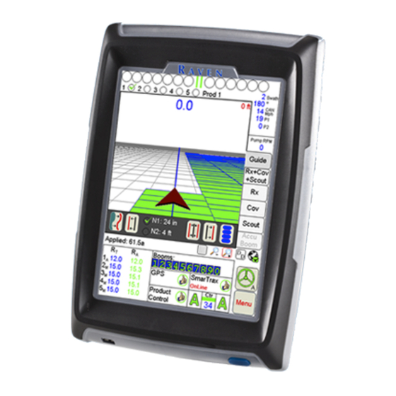
Chapter 2 The Viper Pro Interface The following sections offer an overview of the user interface features of the Viper Pro field computer. Active Matrix Transflective Touch Screen Active Matrix Transflective touch screen technology offers clear visibility across a range of lighting conditions and even in direct sunlight while the touch screen functionality places menus and options literally at the operator’s finger tips. -
Page 17: Front Panel
Make sure to properly close any open jobs before shutting down the computer. A USB port is conveniently located on the front of the Viper Pro field computer. Insert a USB flash drive into this port to transfer compatible Viper Pro files. Note: The USB flash drive must be set up with the Viper Pro file structure. -
Page 18: File Transfer
PC for archiving and printing job reports. The Viper Pro is compatible with USB flash drives with between 256 MB and 4 GB of storage and should be used to manually transfer files to and from the field computer. -
Page 19: Rear Panel
Introduction Rear Panel The following is a brief introduction to the ports and connectors available on the back of the Viper Pro field computer. The rear panel offers additional USB ports as well as an ethernet port for wireless capabilities using an optional Slingshot Field Hub. -
Page 20: Viper Pro Care And Use
Chapter 2 Viper Pro Care and Use Refer to the following guidelines for proper care and use of the Viper Pro field computer. CAUTION • Do not apply any type of liquid or glass cleaner directly to the surface of the touch screen. Harsh chemicals may damage the touch screen. - Page 21 Introduction Amp Connector Pin Definitions Main Amp Auxiliary Amp Connection Connection Main Amp Connector Auxiliary Amp Connector Battery Negative Auxiliary DSR Ext. Switch Ext. Switch CAN Hi CAN Hi CAN Lo CAN Lo DGPS Receive Auxiliary DCD DGPS Transmit Not Used DGPS CTS Auxiliary Receive DGPS RTS...
-
Page 22: Updates
Chapter 2 Updates Updates for Raven manuals as well as software updates for Raven consoles are available at the Raven Applied Technology Division web site: www.ravenhelp.com At Raven Industries, we strive to make your experience with our products as rewarding as possible. -
Page 23: Installation, Start Up And Registration
C h a p t e r 3 and Registration Overview of the Installation Process The following sections are intended as an overview of the Viper Pro installation process. These instructions cover basic installation of the Viper Pro field computer and supplied components and cabling. Note: For instructions on installing additional hardware with the Viper Pro, refer to instructions provided with the additional or optional component(s). -
Page 24: Kit Contents
Chapter 3 Kit Contents Before proceeding with the installation of the Viper Pro system, review the following components of the Viper Pro kit: Viper Pro Chassis Cable Platform Components TABLE 1. Part/Description Part Number Console, Viper Pro 063-0172-879 Manual, Viper Pro... -
Page 25: Mounting The Field Computer
• The Viper Pro should be mounted in a location where it will not be jarred during normal equipment operation. Keep the field computer clear of moving elements within the machine’s cab. •... -
Page 26: Cable Platforms And Connections
Chapter 3 Cable Platforms and Connections Two cable platform options are available for use with the Viper Pro field computer. Each platform offers a range of optional features which can be added to the control system at any time. The Viper Pro field computer may be installed with either the generation 1 or generation 2 cable platform. -
Page 27: Generation 1 Cable Connections
Installation, Start Up and Registration Generation 1 Cable Connections Ensure that the field computer has been properly mounted and all component cabling is connected properly before connecting the Viper Pro to power. Interface Cable Connection Diagram FIGURE 2. To Field Computer... - Page 28 If more than 1 amp is required to power a device connected to the orange wire, install a relay to switch the higher currents. Relay (P/N 415-1001-009) Terminals FIGURE 3. Batt + Batt - 12V Switched to Node Power To 12V Switched Orange Wire Key Switch Viper Pro Installation & Operation Manual...
-
Page 29: Generation 2 Cable Connections
Generation 2 Cable Connections The chassis cable platform requires the following components: • Machine specific chassis cable • Viper Pro chassis interface cable (P/N 115-0172-001) • CAN Switch Box kit (P/N 117-5020-002) Generation 2 Cable Connection Diagram FIGURE 4. Manual No. 016-0171-122 Rev. I... - Page 30 Insert this connector into the ‘To Cab Cable’ on the chassis cable previously installed on the vehicle. Thread the connectors together to secure the connection. Route the end of the cable with two round connectors to the back of the Viper Pro and connect to the main and auxiliary ports.
-
Page 31: Dgps Receiver Connection
Signal from a DGPS receiver must be routed into the Viper Pro via the serial connector labeled ‘GPS Receiver/ DGPS’ on the main interface or chassis interface cable. For information on configuring the Viper Pro to receive signal from the connected DGPS Receiver, refer to the Serial Communication Port Setup section on page 163. -
Page 32: Canbus Network Connection
CAN systems allow product nodes to be added to expand the number of control channels on the system at any time. Ten product control nodes can be connected to the Viper Pro control system for any combination of liquid, granular, chemical injection, or spinner control applications. -
Page 33: Start Up
To start up the Viper Pro: Press the power button on the Viper Pro. The field computer will take approximately 2 minutes to power up. Note: Pressing the power button when the following prompt is displayed on-screen will launch the touch screen calibration wizard without displaying the Program Selection Menu. - Page 34 Chapter 3 The Program Selection Menu will display if the Viper Pro was powered off at this screen the last time the field computer was on. Note: To skip the Program Selection Menu next time the Viper Pro is powered up, shutdown the field computer from the Viper Pro application.
- Page 35 Installation, Start Up and Registration If the Viper Pro is set as the CAN Controller, the Viper Pro will attempt to establish communication with the CANbus system. The CAN Initialization Results screen displays the results of CANbus detection. If the status of the CAN nodes is displayed properly, touch the Start Viper button to finish the start up sequence.
-
Page 36: Touch Screen Calibration Wizard
Touch Screen Calibration Wizard When the operator touches an area of the screen, the Viper Pro displays an arrow in the area where the selection has been made. If this arrow does not appear in the correct location, the touch screen may require recalibration. -
Page 37: Registering The Viper Pro
Registering the Viper Pro The Viper Pro must be registered if an optional feature activation key such as the multi-product VRA, AgX prepopulated jobs or a weather station will be activated. Activation keys are specific to each Viper Pro. Once activated, a purchased key may not be transferred to another field computer. -
Page 38: Activation Key Request
On the main screen, touch the Menu button. Select Setup then Reg. Keys to display the Validation Data screen. Write down the Machine ID and Validation Code from the Viper Pro field computer on the Registration Code sheet; an example is shown below. - Page 39 The above values are for example purposes only. If additional features (such as multi-product VRA or weather module) have not been purchased, the registration code sheet will not be supplied. Write down the machine ID and validation code from the Viper Pro system on a blank piece of paper for future use.
- Page 40 Fill in the machine ID, validation code, and registration code from the registration code sheet. Click the Next button. Fill in the requested information and then click Next. If the registration was processed successfully, prompt similar to the following will be displayed. Viper Pro Installation & Operation Manual...
- Page 41 Locate the product Activation Key. Note: Print and save this page for future use. Back on the ‘Key 1’ screen on the Viper Pro, use the on-screen keyboard to enter the activation key received from the Raven web site (see step 8). Note: If the Viper Pro has been registered previously, touch the Menu button on the main screen and select Setup, then Reg.
- Page 42 Chapter 3 Viper Pro Installation & Operation Manual...
-
Page 43: Initial Set Up And Navigation
Navigation Detecting CANbus Nodes The Viper Pro must be able to communicate with the CANbus system to make sure product is being applied correctly. Viper Pro should automatically establish communication with the boom/speed node and all product nodes connected to the CANbus. -
Page 44: Can Initialization Results
Re-Addressing Product Nodes If the Viper Pro cannot detect a CAN product control node (i.e. single product node, dual product node, motor control node, etc.) during the start up sequence, troubleshoot the CANbus and the node, and then re-address... - Page 45 To power cycle a node, temporarily disconnect the logic power connector from the node, wait a few seconds and reconnect. Touch the Next button on the Viper Pro to cycle the next product node in the system. Repeat steps step 3 and step 4 until all product control nodes in the system have been re-addressed.
- Page 46 For example, enter a value of ‘9005’ in the valve cal to enable all five control channels on the air cart node. Touch the OK button until the Viper Pro main screen is displayed. Select the Menu button in the lower, right corner of the display and select the Exit, Exit to Menu options.
-
Page 47: Initial Set Up
Initial Set Up and Navigation Initial Set Up The first time the Viper Pro is powered up, the field computer will require the operator to input information about the machine and the type of applications, products and setup any additional features connected to the system. -
Page 48: Product Control Type
Viper Pro to control application of a product during a field application. If the Viper Pro will be connected to a separate Raven rate control console via a serial cable, select the specific rate controller from the list of controller model options. -
Page 49: Speed Sensor Type And Cal
Use the Wheel option if a magnetic type, such as a wheel or drive shaft magnet, system is used with the Viper Pro. Set the speed sensor setting to the Radar option if a radar or GPS unit is sending speed information to the Viper Pro. -
Page 50: Application And Control Valve Type(S)
Chapter 4 Application and Control Valve Type(s) The application and control valve type settings configure the Viper Pro for the type of product applied with the control system and how the products will be applied. Touch within the Product Control area at the bottom of the main screen. - Page 51 Contact a local Raven dealer for purchasing information and refer to the Registering the Viper Pro section on page 27 to enter the activation code to unlock the Gran 4 and Gran 5 application type selections.
-
Page 52: Rate Cal(S)
Repeat the above process for any remaining nodes or product control channels as necessary. Touch OK to save the entered value or proceed to the Valve Cal(s) section on page 44 to continue with the initial set up process. Viper Pro Installation & Operation Manual... -
Page 53: Spreader Constant And Product Density
Initial Set Up and Navigation Spreader Constant and Product Density Note: The spreader constant and product density settings are required when the corresponding product node or control channel will be controlling application of a dry, or granular, product. If the product node or control channel is set to control application of a liquid product, refer to the Meter Cal(s) section on page 42. -
Page 54: Valve Cal(S)
Note: To maintain accuracy of the Viper Pro control system, the density value should be adjusted as the measured density of the granular product changes throughout the application. Touch within the Product Control area at the bottom of the main screen. -
Page 55: Dual Loop Control Cals
Initial Set Up and Navigation Valve Cal 2 (Optional) The valve cal 2 value may be used to fine tune control valve response and reduce application rate oscillations when using a Fast Close, PWM or PWM Close control valve. Fast Close Valves. When using a fast close valve to control product application, valve cal 2 is utilized to enable a high resolution rate control for lower application rates. -
Page 56: Boom Or Section Cal
Touch the Number of Boom Sections value and enter the corresponding number of the highest boom sense connector used by the application system. Note: The total number of booms may include “skipped” sections or boom sense wires not connected in some cases. Raven boom sense wires are color coded as follows: Section Lead Wire Section... - Page 57 Initial Set Up and Navigation Fore or Aft Offset The fore/aft offset is the distance of the boom or implement in front or behind the GPS antenna. Note: The fore/aft offset must be measured perpendicular to the boom or implement width. See Figure 1 below.
- Page 58 Touch the Next button to continue to the Boom Section Setup screen. Use the on-screen keypad, enter the width of each boom or implement section in the corresponding field. Note: Enter a section width value of zero for skipped boom sections. Viper Pro Installation & Operation Manual...
- Page 59 Press Next when all of the section width information has been entered. The boom summary screen displays. Note: If the section widths do not match the overall guidance width, the Viper Pro will display a ‘Boom Setup Warning’ to alert the operator to a potential issue. Review the section configuration and select: •...
-
Page 60: Profiles
If the Viper Pro will be used with different machines or application equipment, profiles allow the operator to quickly re-configure the field computer for the specific application and equipment type. -
Page 61: Powering Down The Viper Pro
Initial Set Up and Navigation Profile Changes If any of the settings saved within a profile are changed during operation of the field computer, the Viper Pro will prompt the operator to save the current profile settings before the field computer is powered down. - Page 62 Refer to the Start Up section on page 23 for details on the Program Selection Menu options. If a Job is in progress when the exit button is selected, the Viper Pro will display a warning alerting the operator. Raven recommends closing any open jobs before exiting the Viper Pro application to avoid losing job information.
-
Page 63: Navigating The Viper Pro Interface
Note: The Viper Pro may also display an on-screen light bar at the top of the screen during an active job. Refer to the Light Bar Guidance section on page 168 to enable the on-screen light bar feature. - Page 64 The Viper Pro is also using the displayed speed value for speed compensated product rate control. If ‘GPS’ is displayed in the speed area, the Viper Pro is monitoring speed from a GPS receiver (e.g. an Invicta or Phoenix series receiver). ‘GPS’ will be displayed when the Viper Pro is connected to an optional Raven serial control console.
- Page 65 (if available) to help navigate between fields. Note: Refer to the Street Maps section on page 152 for assistance loading street maps on the Viper Pro field computer. The Main tab view also displays the active profile at the top of the screen.
- Page 66 Viper Pro regardless of current GPS location. Note: To return to the current GPS position, select the Vehicle Lock icon.
- Page 67 To review current alarm information, touch the alarm icon to display information such as the control channel and alarm type currently active. Wireless Communication Status The status of wireless communications is displayed on the Viper Pro main screen in the tool bar below the map. Wireless...
- Page 68 Touch within the Booms area accesses the AccuBoom Control Setup screen. If the required hardware has been installed, the Viper Pro can be used to automatically control boom sections based on the coverage map or other scouting information such as a field boundary. See Chapter 9, Using AccuBoom™, for a detailed description of the AccuBoom feature.
- Page 69 Screens section on page 144 for details on using the GPS Status screen. When connected to a compatible GPS receiver, the Viper Pro will display the source of GPS corrections currently received. An audible tone will sound anytime the correction source changes. The Viper Pro will display the following on the Main screen: •...
- Page 70 CAN Controller Status screens on the Viper Pro field computer. SmarTrax Status Area and Steering Indicator If an optional SmarTrax or SmartSteer system is installed with the Viper Pro, the status of the system will be displayed in this area.
- Page 71 Viper Pro field computer via the Raven CANbus system. Menu Various configuration and feature settings for the Viper Pro control system are accessible via the ‘Menu’ button in the lower, right corner of the Viper Pro display.
-
Page 72: Controller Status Screen
The Controller Status screen displays information from the product rate controller or a CANbus control system. Controller Status When connected to a separate product rate control console, the Viper Pro Controller Status screen displays boom section and product rate information provided by the rate controller. The following is an example of the Controller Status screen with the Viper Pro configured to interface with a Raven SCS 460 console. - Page 73 Initial Set Up and Navigation CAN Controller Status When configured to interface with a CAN network, the current control settings for each product node or control channel are displayed on the CAN Controller Status screen. The following information areas display on the CAN Controller Status screen: Boom Cals Miscellaneous Area...
- Page 74 • The Current Alarms button is displayed only when an alarm condition is detected by the Viper Pro during an active job. Refer to the Alarms section on page 101 for detailed information on alarm conditions. Viper Pro Installation & Operation Manual...
-
Page 75: Using The Viper Pro System
System Overview of Job Files and Features The Viper Pro uses jobs and job files to automatically log data in the field during operations using the application management system. During an active job, the Viper Pro collects the following information: •... -
Page 76: Overview Of Job Types
Overview of Job Types The Viper Pro is compatible with the following job types for operation as a stand alone system or as a part of a full crop data software package. - Page 77 Raven CANbus using Raven product nodes. Each node provides a single control channel for controlling the application of a single product. So, if the Viper Pro is connected to a CANbus with a single product node, the Viper Pro will monitor or control for one product during an active job. Up to ten product nodes may be connected to the Viper Pro to control any combination of liquid, granular, injection or spinner channels as necessary.
- Page 78 Chapter 5 AccuBoom™ Control The AccuBoom control feature allows the Viper Pro to automatically turn the boom sections on or off in reference to a coverage or as-applied map. As the boom enters an area where product has previously been applied, AccuBoom will control boom sections off.
-
Page 79: Starting A New Agx Job
If AgX recommendations have not been transferred to the field computer, or if the AgX activation code has not been entered and validated, the Viper Pro will display a prompt. Contact a local Raven dealer to acquire an AgX activation code or refer to AgX File Maintenance section on page 200 for assistance transferring recommendations from a USB flash drive to the Viper Pro. - Page 80 To view a complete list of recommendations stored on the Viper Pro, select the Show All option. A list of recommendations currently stored on the field computer will be displayed.
- Page 81 Using the Viper Pro System When the correct recommendation is selected, touch the Next button to display the Assign Recommendation to Channel screen. This screen displays the available control channels and any recommendations available for the selected field. If the Viper is controlling more than one product via a CANbus, the Chain Profile selection will be displayed at the top of the screen.
-
Page 82: Assign Or Create A Product Chain Profile
The existing profile settings will be displayed and may be changed as necessary. The profile name will not be updated automatically while editing an existing chain profile. To remove chain profiles from the list, select the profile name and touch the Delete Entry button. Viper Pro Installation & Operation Manual... - Page 83 Select the Enable Auto Advance option to allow the Viper Pro to automatically advance to the next product in the chain. If the auto advance feature is disabled, the Viper Pro will display a prompt to allow the operator to manually advance to the next tank or bin.
-
Page 84: Selecting Control Channels
Note: Recommendations may be assigned to any product during the job setup. During the job, Viper Pro will display any “skipped” control channels and the operator may control application of a product using these channels if necessary. “Skipped” channels will not have a product name associated with the control channel and the application report will need to be adjusted for these skipped products. -
Page 85: Booms
Confirm the boom or section selections are correctly set up for the equipment being used. Note: The boom or section selections are also accessible before setting up a job through the Product Control area on the Viper Pro Main screen. Refer to the Section Assignments section on page 130 for more information. Default Rate Touch the Default Rate button to enter a standard rate of application for the channel when no prescription information is available. -
Page 86: Machine Control Settings
Standard AccuBoom - This method requires no action or additional setup by the operator. The operator simply begins to apply product to the field and the Viper Pro monitors the coverage map and will turn sections off if the boom enters into a previously applied area. -
Page 87: Starting A Standard Job
Using the Viper Pro System Starting a Standard Job To begin a standard job and use the Viper Pro to enter all product and job information: Select Menu, then Start Job. Select New Job. The New Job screen displays. Note: A Program D or later boom/speed node is required to use AccuBoom™... - Page 88 Standard AccuBoom - This method requires no action or additional setup by the operator. The operator simply begins to apply product to the field and the Viper Pro monitors the coverage map and will turn sections off if the boom enters into a previously applied area.
- Page 89 Using the Viper Pro System Press Next. If Product Application was selected, the Product Selection screen displays. CAN nodes are controlled in a sequential manner and each single product node provides one product control channel. The operator may only enable the number of control channels currently available on the machine when setting up a new job.
-
Page 90: Enabling Product Chaining
Touch Next. Select the Enable Auto Advance option to allow the Viper Pro to automatically advance to the next product in the chain. If the auto advance feature is disabled, the Viper Pro will display a prompt to alert the operator to manually advance to the next tank or bin. -
Page 91: Product Setup
Using the Viper Pro System Press Next. The final Product Chain Setup screen displays. Set the product name and options for chained tanks or bins before any non-chained products. Refer to the Product Setup section on page 81 for details on setting product information for products not controlled in a product chain. - Page 92 Chapter 5 Press Browse to display a list of folders or prescription maps stored in the Viper Pro file structure. Note: If an AgX recommendation is available on the Viper Pro, the AgX prescription map files can be loaded into a standard job by accessing the AgXRec folder on the above screen.
-
Page 93: Prescription Rate Conversions And Default Rates
Using the Viper Pro System Prescription Rate Conversions and Default Rates When product setup is complete for each enabled product, the Rate Conversion screen will be displayed if any prescription maps have been assigned to products. Rate Conversions may be used to calibrate prescription maps for the application. Enter a value of ‘2’ to double the prescription rates on the selected prescription map or a value of “0.8”... -
Page 94: Existing Jobs
Chapter 5 Existing Jobs Jobs previously created on the Viper Pro may be reopened to complete report information or to resume a field operation. The following options are available when opening an existing job file: • View the existing job •... -
Page 95: Using An Existing Field Boundary
Touch the ‘Start New Job’ button to begin a new job using the displayed in the preview. The Viper Pro will begin the job set up process for a new job. Refer to the Starting a New AgX Job section on page 69 for information on completing the job set up process. When the new job is ready to begin, Viper will prompt the operator to select whether the previous job coverage information should be saved or deleted. -
Page 96: Pausing And Resuming Jobs
To help reduce the file size of completed jobs and to help minimize the time required to perform file maintenance, jobs may be paused to keep the Viper Pro from logging data not necessary for the job report. -
Page 97: Application Rates Area
Using the Viper Pro System Application Rates Area Use the Application Rates area to quickly check the status of each configured product node or control channel during product application. Note: The “Application Rates” heading will be hidden if multiple product nodes or control channels are enabled to allow all information to be displayed on the main screen. -
Page 98: Tabs
Main Tab The main tab is only available when a job is not in progress on the Viper Pro. This tab displays county street maps (if available) to help the operator locate fields or areas for product application and any saved field boundary features currently stored on the Viper Pro internal memory. -
Page 99: Guide Tab
If the swath guidance feature is enabled during the job setup process, touch the Guide tab during the job to access the swath guidance tools and features or to toggle between the available guidance patterns. Note: Refer to Chapter 6, Viper Pro Guidance, for detailed information on using the guidance features on the Viper Pro field computer. Rx+Cov+Scout Tab Access the Rx+Cov+Scout tab to view scouting, coverage and any prescription map information in the same map view. -
Page 100: Rx Tab
Touch the Rx tab and select the appropriate product node or control channel above the map display. Select the Prescription icon from the map tools display below the map area. Touch an area or zone on the map. The Viper Pro displays prescription rate information for the selected map area. -
Page 101: Cov Tab
Touch the Cov tab and select the appropriate product node or control channel above the map display. Select the Prescription icon from the map tools located below the map area. Touch a field area or zone on the map. Viper Pro displays product coverage information for the selected area. -
Page 102: Scout Tab
Access the Scout tab to record a zone, path or point to mark a field feature during an active job. Refer to the Scout Tab section on page 92 to customize the scout map display on the Viper Pro. Refer to the Marking a Field Feature section on page 93 for details on the available features and zones. -
Page 103: Accuboom™ Tab
Field features, zones and areas may be mapped using the following types of paths or points: Single Point. Select the single point feature to plot a single location on the scout map. The Viper Pro automatically plots the point at the selected location. -
Page 104: How To Mark A Field Boundary
Scout tab and touch the “Rocks Point” button displayed in the map area to plot a point at the current vehicle location. The Viper Pro scout map may then be used to help re-locate the rocks at a later date for removal. - Page 105 Using the Viper Pro System Auto Point Entry. The Viper Pro automatically records points along the driven path to create the boundary in real-time. The field computer will also automatically close the field boundary when the vehicle comes within one boom or implement width of the starting point. The operator may also close the boundary manually if desired.
-
Page 106: Importing A Field Boundary
To close the field boundary, select one of the following options: • Continue driving the field boundary until the Viper Pro automatically closes the boundary. Viper Pro will automatically close the boundary if the vehicle returns to a position within one boom or implement width of the boundary start point. - Page 107 Select ‘Field Boundary’ and then touch the Import Field button. The Select Field Shape File screen displays. Select a file from the list and touch OK. The Viper Pro will import a compatible shapefile into the job in progress. Manual No. 016-0171-122 Rev. I...
-
Page 108: Tally Registers
Chapter 5 Tally Registers The tally registers feature of the Viper Pro may be used to track area and volume totals over the course of a field application or over the course of an application season. To view or reset current tally totals from the Viper Pro main screen: Touch the Product Control area at the bottom of the main screen. -
Page 109: Resetting The Tally Registers
Using the Viper Pro System This screen also displays the overall distance traveled by the vehicle as calculated by the Viper Pro using the speed sensor and programmed speed cal. Touch the Next button on the Tally Registers screen to view the Odometer screen. Continue touching the Next button to view the Tally Registers for each product control node in the Viper Pro CANbus system. -
Page 110: Setting Or Resetting Distance And Individual Nodes
Touch the Next button on the Tally Registers screen to display the Viper Pro Odometer screen. Using the on-screen keyboard, enter the desired distance values in the appropriate fields. Touch the Set button to save the entered values. To reset the Odometer, touch the Reset button. The Viper Pro odometer is reset to zero. -
Page 111: Alarms
Using the Viper Pro System Alarms If the Viper Pro is configured as the CANbus controller, the field computer will display a specific warning prompt for any configured alarm conditions encountered. Any new warning conditions encountered by the field computer will be displayed automatically when the condition is detected and will contain information to assist the operator with addressing the alarm condition. -
Page 112: Addressing Alarm Conditions
Chapter 5 Addressing Alarm Conditions To view any current alarms detected on the CANbus system from the Viper Pro main screen: Touch the Product Control area at the bottom of the screen. Select the Current Alarms button at the bottom of the CAN Controller Status screen. The Current CAN Node Alarms screen displays: To acknowledge the warning, but keep the warning information accessible, touch the OK button. -
Page 113: Creating Application Reports
Information such as field, product(s) and weather information contained in the application report may be entered during the job on the Viper Pro or on a home or office PC. The Viper Pro creates reports in both shapefile and bitmap (.bmp) formats. The shapefile report will require a shapefile editing program to enter ®... -
Page 114: To Enter Report Information
Use the Field Information screen to enter field information and the crop type if applicable. Note: The Viper Pro will store field and crop information entered on the field computer. Select a field name or crop type entered during a previous operation and the field computer will automatically enter the information from the previous job. - Page 115 Use the second Field Information screen to enter application type, soil condition, and moisture information for an operation. Conditions entered for previous jobs may be selected from the drop down lists if applicable. The Viper Pro will automatically store any field information entered on the field computer.
- Page 116 Use the Applicator Information screen to enter the operator or custom applicator address and license number. The Viper Pro will store any applicator information entered on the field computer. Select the operator name from the drop down list to automatically enter the applicator information for future jobs.
- Page 117 EPA number, and targeted pests as applicable. The Viper Pro will store any chemical information entered on the field computer. If the operator selects the product for a future job, the manufacturer and EPA number will be automatically entered on this screen.
- Page 118 Use the Report Notes screen to enter any additional notes for the job report. Use the Prev and Next buttons as necessary to review and modify the job report information before touching OK to accept the displayed information and return to the Viper Pro main screen. Viper Pro Installation & Operation Manual...
-
Page 119: Viper Pro Guidance
C h a p t e r 6 Note: A DGPS receiver is required to use the Guidance features of the Viper Pro. Contact a local Raven dealer for additional assistance with compatible receiver options. Non-Raven DGPS receivers may also be used with the Viper Pro. To avoid issues with connection and compatibility, contact the receiver manufacturer or a local dealer for additional information and receiver capabilities before purchasing. -
Page 120: Swath Guidance Patterns
Setting the Straight (A-B) Line Pattern If Swath Guidance is enabled, the Viper Pro will automatically display the ‘Guide’ tab when a job is opened. To begin swath guidance with the straight (A-B) line pattern: Touch the Set A button to set the first point on the path at the current vehicle location. - Page 121 Viper Pro Guidance Drive to the end of the swath and touch the Set B button on the screen. Once the B point is set, Viper will create a straight guidance line displayed in blue. Manual No. 016-0171-122 Rev. I...
-
Page 122: Set A-B Line By Heading
Touch one of the compass heading arrows to set the heading along a compass heading. Touch the Use Current Heading button to use the current vehicle heading shown in the center of the compass display. Use the on-screen keypad to enter any heading between 0 and 360°. Viper Pro Installation & Operation Manual... -
Page 123: Setting The Fixed Contour Pattern
The Last Pass pattern uses the nearest, previously applied area, or last pass, to determine the guidance for the next swath. If headlands areas are present and the Last Pass mode is active, the Viper Pro may display a guidance line along the headlands area instead of the next swath. -
Page 124: Setting The Pivot Pattern
SmartSteer system on the Viper Pro field computer. Setting the Pivot Pattern If Swath Guidance is enabled, the Viper Pro will automatically display the ‘Guide’ tab when a job is opened. To begin swath guidance with the pivot pattern: Start with the machine located at a point on the outside of the center pivot area and touch the ‘Set A’ button on the screen. -
Page 125: Using The Guide Tab
Using the Guide Tab Viper Pro will automatically display the Guide tab when a job is opened. The map area displays a Course Direction Indicator in the form of an arrow with the arrow pointing in the direction of travel of the vehicle. The operator may access additional guidance information and features by selecting the displayed areas or on- screen buttons. - Page 126 The Save A-B button allows the operator to save an A-B line once the line has been set using the Set A and Set B buttons or if the A-B line has been re-calibrated or reset. Viper Pro Installation & Operation Manual...
-
Page 127: Screen Icons
Viper Pro Guidance ReCal A-B Button When using the Straight (A-B) Line guidance pattern, touch the Guidance Menu icon to access the Recal A-B button. Touch the Recal A-B button to recalibrate the displayed A-B line to the current machine location. -
Page 128: A-B Lines
Note: When saving lines, use unique names to help distinguish each line from other saved A-B lines. Avoid using dates and times as this will make selecting a previously stored A-B line more difficult. Viper Pro Installation & Operation Manual... -
Page 129: Loading An A-B Line
Available A-B Lines Filtering Options If several A-B lines are saved on the Viper Pro, the following filtering options may be used to help locate a specific guidance path: Show all guidance files. This option shows all currently saved paths of the same type selected when the job was created. -
Page 130: Nudge Feature
The in-job nudge settings will only be accessible with an A-B type guidance path (i.e. Straight Line, Fixed Contour, Pivot). To configure the nudge settings in a job: Touch the Guide Menu icon on the Guidance screen. Guide Menu Icon Viper Pro Installation & Operation Manual... -
Page 131: Using The Nudge Feature
Select the ‘Save these settings as default for future jobs’ option to save these nudge values with the Profile. If this option is selected, the nudge values will be available at the start of each job started on the Viper Pro. - Page 132 Chapter 6 Viper Pro Installation & Operation Manual...
-
Page 133: Product Chaining
P roduct Chaining CHAPTER C h a p t e r 7 The product chaining feature allows the operator to link product tanks or bins together when applying product to a field. When one tank or bin runs out, Viper automatically switches application to the next tank or bin to continue applying product. -
Page 134: Using Product Chaining
When controlling more than five products over a CANbus network, touch the drop down arrow in the upper, right of the screen to switch the map display to other available control channels or the product chain profile. Viper Pro Installation & Operation Manual... -
Page 135: Application Rates Area
Product Chaining Application Rates Area The target rate and control mode for each product in a product chain may be adjusted using the same tools available for nodes or channels controlled individually. Review the Application Rates Area section on page 87 for details on the information displayed in this area and on setting the target rate for product nodes or control channels. - Page 136 The field computer will not provide detailed mapping of the application rates for products in the cleanout mode and will not display low rate zones within the application map. Viper Pro Installation & Operation Manual...
-
Page 137: Product Chain Display Data
Review the Product Chain Prompts section on page 126 for details on product chain prompts displayed during field operations. Touch ‘OK’ to acknowledge the chaining prompt and return to the Viper Pro main screen. Touch within the Application Rates area to display the Application Control screen. - Page 138 Chapter 7 Viper Pro Installation & Operation Manual...
-
Page 139: Advanced Settings And Features
This chapter contains descriptions of advanced settings and features available when controlling a CANbus product control system with the Viper Pro field computer. The following settings and features are not required for operation of the Viper Pro system and are intended to assist with various operations using the Viper Pro field computer. -
Page 140: Section Assignments
A liquid chemical is not supplied to fence row nozzle sections. To configure the Viper Pro for these equipment configurations, the Boom Select feature must be used. To access the Boom Select screen: Touch within the Product Control area on the main screen and then touch the Boom Cals area on the CAN Controller Status screen. -
Page 141: Miscellaneous Settings Area
Advanced Settings and Features Miscellaneous Settings Area The information displayed in the Miscellaneous area is an overview of the settings and current system status. The Miscellaneous area displays an overview of several current system settings for the system. Note: Touching within the Miscellaneous area will display the Miscellaneous Settings screen. The following information displays are for reference and monitoring purposes only: Fan/Pump RPM Display. - Page 142 “Combo” is selected. Audible Alarm. When the audible alarm setting is enabled, the Viper Pro will sound a five second alarm tone if an alert condition or alarm setting is detected on the CANbus (i.e. low tank or bin, zero speed, off rate percent etc.).
- Page 143 The current percentage of the entered maximum boom capacity is displayed. If the actual rate of application reaches 90% or more of the maximum boom capacity, the Viper Pro will display the Boom Capacity Display Data prompt to alert the operator to the application condition.
-
Page 144: Feature Settings Area
Touch within the Feature Settings area to view the first screen of settings for the selected product node or control channel. Note: Touch the Next button to access additional alarm and feature settings for the selected product node or control channel. Viper Pro Installation & Operation Manual... - Page 145 If a non-zero value is entered for this setting and the difference between target and actual rate exceeds the set value for longer than five seconds, the Viper Pro will display an off rate alarm. Enter a value of zero to disable the off rate alarm.
- Page 146 Enable the bin alarm for granular applications if an optional bin level sensor is installed. With this feature enabled, the Viper Pro will display an alert when the sensor detects the product level in the bin falls below the sensor level.
- Page 147 Advanced Settings and Features Agitator. The Viper Pro may be used to enable or disable an agitator to continuously mix a chemical suspension. Contact a local Raven dealer for required hardware. Display Smoothing. Enable the display smoothing feature to allow the field computer to smooth the rate displayed during product applications.
-
Page 148: Product Control Settings Area
Before changing any of the product control settings, be sure to select the correct product node or control channel by touching the corresponding radio button displayed at the top of the feature settings area. Viper Pro Installation & Operation Manual... - Page 149 Tank Volume. Enter the initial volume of product in a tank or bin. As product is applied using the corresponding node or control channel, the Viper Pro will calculate the volume remaining in the tank or bin and display the value on the CAN Controller Status screen, the Tally Registers screen and in the Display Data prompt.
- Page 150 • For liquid product applications, the meter cal must be entered to calibrate the Viper Pro to the specific flow meter used to measure the flow of product going to the booms. The meter cal value is typically found on the flow meter.
- Page 151 Advanced Settings and Features Valve Adv. (Advance - Standard, or Fast Valves). While in the automatic rate control mode, the value entered in the valve advance field sets the time (in seconds) which the field computer will allow the control valve to remain open after boom sections are toggled off.
-
Page 152: Dual Pressure Area
Valve Delay. Set the valve delay to include a time delay between when the booms are turned on and when the product nodes start to control the flow rate. Viper Pro activates this delay if the time between turning the boom on and off is less than 30 seconds. -
Page 153: Application Area
The application area on the CAN Controller Status screen displays the current application type and control valve type configured on for the Viper Pro control system. Refer to the Application and Control Valve Type(s) section on page 40 for information on these settings. -
Page 154: Gps Status Screens
DGPS reception. Reverse Sense. The reverse sense feature enables the field computer to detect when the vehicle is backing up. With the reverse sensing feature turned off, the Viper Pro will always display any vehicle motion in the forward direction. -
Page 155: Smartrax Settings Screens
While travelling at least 2 mph [3.2 km/h], select the current direction of travel to calibrate the Viper Pro for automatic reverse detection. This feature may be helpful when backing into corners while spraying with AccuBoom enabled. -
Page 156: Autoboom™ Status Indicator
Status Icon Note: For more information on using the wireless communication features with the Viper Pro, see Appendix J, Wireless Communications and Remote Service. For instructions on installing and setting up the Slingshot Field Hub, refer to the Field Hub Installation Guide provided with the wireless device. -
Page 157: Menu
Viper Pro field computer. Exit Button From the Viper Pro main screen, touch Menu and select the Exit option to display the Exit Viper prompt. Select the following options to: Note: If a Job is in progress when the exit button is selected, the Viper Pro will display a warning alerting the operator. - Page 158 CAN Firmware Version. This value displays the current version of firmware used for CAN communication. Note: Version 16 or higher CAN firmware is required to allow the Viper Pro to update nodes over the CANbus. BIOS Version. The BIOS version currently used by the Viper Pro field computer.
-
Page 159: Web Button
Web Button If the Slingshot Field Hub, or similar hardware, is connected to the ethernet port on the back of the Viper Pro, touch Menu, and select the Web button to access the world wide web on the Viper Pro touch screen. -
Page 160: Setup Button
This feature allows the operator to transfer files to or from the Viper Pro field computer using either a USB flash drive or to set up automatic file transfer options when using a Slingshot Field Hub. -
Page 161: Start Job
The job file automatically logs coverage information for reference at a later date and creates coverage reports for viewing on a home or office PC. Refer to Chapter 5, Using the Viper Pro System, for detailed information about using the Viper Pro during field applications. -
Page 162: Maps
Coverage, scout and prescription (Rx) map displays may be customized to suit the equipment operator or application through the map option in the setup menu. To set map display options from the Viper Pro main screen, touch Menu and select Setup and Maps. The following actions may be performed through the Maps setup menu: •... - Page 163 On the Advanced File Maintenance screen, select: Street Map, then Copy or Move. To move files from the USB drive to the Viper Pro, select the External --> Viper option, and Copy All or Copy Selected. Viper will upload streetmaps files to the internal memory.
-
Page 164: Scout Maps
Scout map features may be recorded at any time during an active job. To Configure the Scout Map Features and Mapping Colors From the Viper Pro main screen, touch the Menu button, then select Setup, Maps, and Scout Map. The Enter Feature Names and Colors screen is displayed. -
Page 165: Coverage Maps
93. Coverage Maps During an active job, the Viper Pro creates an as-applied or coverage map containing real-time product rate information for each active product. The equipment operator may reference the coverage map to view areas of a field application in which: •... - Page 166 Proceed to the next section for details on the zero rate tolerance setting. Zero Rate Tolerance The zero rate tolerance values set the minimum number of pulses detected by an encoder before the Viper Pro will record coverage for the product.
-
Page 167: Prescription (Rx) Maps
Setting the Zero Rate Tolerance. To set the zero rate tolerance for each node from the Viper Pro main screen, touch Menu, then Setup, Maps, and Cov Map. - Page 168 [27.4 m] wide. To load a prescription map shapefile onto the Viper Pro, the .shp, .shx and .dbf files must be copied into the RxMaps folder on the USB flash drive used with the Viper Pro. Refer to the Uploading Prescription Maps from a USB Flash Drive section on page 194 for detailed instructions.
- Page 169 If no color template is selected by the operator, the Viper Pro will use the default colors. Adding a Prescription (Rx) Map Color Template To add or create a prescription map color template from the Viper Pro main screen, touch Menu, then Setup, Maps, Rx Maps, and Rx Colors. The Rx Map Colors prompt will display.
- Page 170 The last range value entered will be the minimum rate for the highest rate range. When a rate range and display color have been entered for each field, touch OK. The Viper Pro will display a confirmation prompt.
- Page 171 From the list of existing templates stored on the Viper Pro, select the desired template to delete and touch The Viper Pro will display a prompt to confirm that the template file will be deleted. Touch Yes to delete the selected template.
-
Page 172: Local Settings
Power Option The automatic power down feature allows the Viper Pro to automatically close any active job file and power down the console when the vehicle ignition is switched off. This feature may be enabled to help ensure that job information is saved and the field computer is properly powered down. -
Page 173: Serial Communication Port Setup
GPS Comm Port Setup To use the guidance capabilities of the VIper Pro field computer, a DGPS receiver must be connected to the 9-pin serial connector labeled ‘DGPS’ on the main interface or chassis interface cable. The GPS Comm Port Setup screen is used to configure the Viper Pro field computer to receive GPS messages from the connected receiver. - Page 174 VTG, and either the RMC or ZDA NMEA messages to communicate properly with the Viper Pro. To configure the Generic GPS preset from the Viper Pro main screen, touch Menu, then Setup, and Comm Ports. The GPS Comm Port Setup screen displays.
- Page 175 Stop Bit = 1 • Parity = None Touch the View Data button to confirm that the Viper Pro is receiving GPS messages or touch OK to return to the Viper Pro main screen. Note: If the Viper Pro is unable to receive GPS messages from the Raven receiver, refer to Chapter 12, Troubleshooting the Viper Pro System, or contact a local Raven dealer for assistance.
-
Page 176: Console Comm Port Setup
Chapter 8 Console Comm Port Setup The Viper Pro may be configured to log product rate data received from a separate rate control console connected to the field computer via the 9-pin serial connector labeled ‘Console’ on the main interface or chassis interface cable. -
Page 177: Auxiliary Comm Port Setup
Spectrum Technologies WatchDog Sprayer Station. Refer to the Light Bar Guidance section on page 168 or Appendix I, Weather Station, to configure the Viper Pro for these components. To configure the auxiliary comm port settings from the Viper Pro main screen, touch Menu, and select Setup, Comm Ports. -
Page 178: Light Bar Guidance
Enable the desired light bar options: On-Screen Lightbar. Enable this option to display a light bar at the top of the Viper Pro touch screen while guidance is enabled during an active job. The on-screen light bar will be displayed regardless of which tab is active during the job. -
Page 179: Configuring The Light Bar Display
Configuring the Light Bar Display When the on-screen or external light bar options are enabled, the Viper Pro field computer may be used to configure the light bar display. These settings can help the operator set the accuracy of the light bar for different operations or display preferences. - Page 180 Advanced Settings and Features Manual No. 016-0171-122 Rev. I...
-
Page 181: Chapter 9 Using Accuboom
AccuBoom turns the boom section back on. The following sections offer instructions on setting up and using the AccuBoom feature with the Viper Pro field computer. Contact a local Raven dealer for more information and available kits for specific machines. - Page 182 Chapter 9 CAN AccuBoom™ with Viper Pro System Example FIGURE 1. Viper Pro Installation & Operation Manual...
-
Page 183: Accuboom™ Control Setup
Using AccuBoom™ CAN AccuBoom™ with Serial Control Console and Viper Pro System Example FIGURE 2. AccuBoom™ Control Setup Note: The required hardware must be purchased and installed before the AccuBoom system may be configured. The AccuBoom Control Setup screen allows the operator to configure AccuBoom functionality. To access this screen, touch the Booms area on the main screen. - Page 184 Program ‘D’ or newer is required for operation. If the boom/speed node on the CANbus does not have Program ‘D,’ the AccuBoom tab will not be accessible and Viper Pro will display a warning message when an AccuBoom enabled job is opened.
-
Page 185: Configuring Accuboom™ Control
Using AccuBoom™ AccuBoom™ Override Sec The AccuBoom Override feature allows the operator to momentarily apply product to a previously applied area while in a job. This feature is useful when backing into a corner during boundary spraying, to start product application while the vehicle or implement is at a complete stop, or to apply additional product on a heavily infested area of the field. -
Page 186: Accuboom™ Boom Disable
In a granular system with spinner control, disable the node associated with the spinner to allow the spinner to run regardless of previous coverage or AccuBoom no-spray zones. Check Enable Zero Rate Shut Off to enable this feature. Touch the Next button to proceed to the AccuBoom Aggressiveness Factor screen. Viper Pro Installation & Operation Manual... -
Page 187: Accuboom™ Aggressiveness Factor
Using AccuBoom™ AccuBoom™ Aggressiveness Factor The look-ahead values set the amount of time ahead of the vehicle (based on vehicle speed) which the Viper Pro will scan for zone boundaries or unapplied areas when turning boom sections on or off. By default, AccuBoom overrides any additional zone boundaries detected until the look-ahead time has passed. -
Page 188: Enabling Accuboom™ Override
AccuBoom control of all boom sections will be overridden until the time set as the Override Seconds value expires. Once the set override time has run out, AccuBoom automatic section control will resume for all boom sections selected for AccuBoom control. Viper Pro Installation & Operation Manual... -
Page 189: Accuboom™ Spray/No-Spray Mapping
Using AccuBoom™ AccuBoom™ Spray/No-Spray Mapping AccuBoom can be set up to operate based on a variety of different map features that define spray and no- spray zones. The AccuBoom Setup screen allows the operator to select the desired method of operation for AccuBoom. -
Page 190: Create Accuboom™ No-Spray Map Method
This method allows the operator to load a map that has already been created. If this method is selected, touching the Next button will display a screen showing the AccuBoom maps contained in memory. The operator can then select the desired map to load. No further setup is required. Viper Pro Installation & Operation Manual... -
Page 191: Create Map From Field Boundary Method
AccuBoom™ Spray/No-Spray Maps An AccuBoom spray/no-spray map may be created on the Viper Pro before an actual job or product application using the scouting function or the map may be created during the application. The first step in creating an AccuBoom spray/no-spray map is to define the spray and no-spray zones within a field. -
Page 192: How To Create A Spray/No-Spray Map
If an existing field boundary has been selected for use in an AccuBoom enabled job, the selected boundary will be displayed in the Map area. The operator may still define additional zones if necessary for the job. Viper Pro Installation & Operation Manual... - Page 193 Using AccuBoom™ Once all spray and no spray zones are created, select the AccuBoom tab and touch the Create Map button. The spray and no-spray zones previously created will be converted to an AccuBoom spray/no-spray zone map. The previously created spray and no-spray zones will be removed from the Scout tab and will appear as an AccuBoom spray/no-spray map.
- Page 194 Chapter 9 Viper Pro Installation & Operation Manual...
-
Page 195: Using Autoboom
CHAPTER C h a p t e r 1 0 The AutoBoom feature, used in conjunction with Viper Pro, adjusts the height of booms automatically. Using the machine hydraulics, the AutoBoom parallel hydraulic system always keeps the hydraulic valves open, gently balancing the hydraulic cylinders and allowing the booms to descend or elevate effortlessly. -
Page 196: Autoboom™ Status Display
If a center ultrasonic sensor is installed, Ctr Ht is displayed in the AutoBoom area in place of the set height. Refer to the CAN AutoBoom Calibration and Operation Manual for detailed instructions on calibrating and operating either the UltraGlide or PowerGlide Plus AutoBoom systems with the Viper Pro field computer. Viper Pro Installation & Operation Manual... -
Page 197: File Maintenance And Editing Reports
To view existing jobs, or add to field applications at a later date, all files associated with those jobs must be transferred back to the Viper Pro field computer. Be sure to backup or save files for any jobs that may need to be resumed at a later date. -
Page 198: Preparing A Usb Flash Drive For File Maintenance
Chapter 11 If a Slingshot Field Hub is connected to the Viper Pro, files may also be transferred wirelessly to the Slingshot web site. A user account will be required to access files transferred to the Slingshot web site on a home or office PC. - Page 199 Touch OK. The necessary file folders will be loaded onto the thumb drive. Touch OK to return to the File Maintenance main menu. The USB flash drive will now be populated with the necessary file folders needed by the Viper Pro. Manual No. 016-0171-122 Rev. I...
-
Page 200: Flash Drive File Structure
If the USB flash drive was initialized with an older version of software, an Rbin folder may also be available. This folder would contain any Rbin files from the Viper Pro. This file is not used with newer software versions and may be deleted if desired. Verify that the Rbin folder is empty before deleting the folder. - Page 201 Field Boundaries created using the Viper Pro are saved as a part of the job file. Clone. The clone sub-folder will only appear on the USB drive if a clone of the Viper Pro has been created. Clones may be used as “restore points” to quickly and easily reset the Viper Pro field computer to a previous set up.
-
Page 202: Performing File Maintenance
Chapter 11 Performing File Maintenance Viper Pro provides flexible options for managing and maintaining files stored on the Viper Pro field computer. To access the File Maintenance feature: Touch Menu on the Viper Pro main screen. Select File Maint. The following file maintenance options will be displayed. -
Page 203: Wireless File Transfer
Wireless File Transfer The Wireless File Transfer button is displayed only if a Slingshot Field Hub is connected and communicating with the Viper Pro field computer. Select this option to setup the desired method for initiating file transfer via a wireless connection. -
Page 204: Uploading Prescription Maps From A Usb Flash Drive
Select USB RxMap Upload from the list of file maintenance options. The following warning screen will display. Touch OK to upload the prescription maps from the USB flash drive to the Viper Pro internal storage or Cancel to abort the upload process. -
Page 205: Usb File Transfer And Advanced File Maintenance
USB flash drive. If a Slingshot Field Hub is connected to the Viper Pro field computer, files may be transferred to the Slingshot web site via the wireless connection. Refer to the Wireless File Transfer section on page 193 for details. - Page 206 Selecting Associated File Actions Some file types may be associated with a job file on the Viper Pro. If job files will be deleted, the operator must choose what action to perform on files associated with the job file being deleted.
-
Page 207: Initialize External Usb Flash Drive
File Maintenance and Editing Reports Selecting File Selection Method Next, select the method to select specific files. • By Age - Select the “by Age” option to set an age for files which the action will be performed upon. The operation will be automatically selected and copied, moved, or deleted. •... -
Page 208: Automatic File Maintenance
Select Automatic File Maintenance from the list of file maintenance options. The following warning screen will display. Touch OK to download the report files from the Viper Pro internal storage and delete associated job files from the Viper Pro or Cancel to abort the downloading of report files. -
Page 209: Clone Or Restore Settings
If a clone has previously been created, select the file name from the list and touch Restore Clone to restore the selected clone on the Viper Pro. To delete a clone, select the file name and touch Delete Clone to remove the selected clone. -
Page 210: Agx File Maintenance
Select External Drive If more than one USB flash drive is connected to the Viper Pro at one time, the ‘Select External Drive’ button will be displayed on the File Maintenance screen. Touch this button to select an external drive. -
Page 211: Uploading Reports To The Slingshot Web Site
Completed job reports may be uploaded to the Raven Slingshot web site using a free Slingshot user account. The Slingshot web site offers tools for creating, editing and archiving job files from the Viper Pro and may also be used to export a job report in the shapefile format. -
Page 212: User Account Sign-Up
Slingshot. Refer to the USB File Transfer and Advanced File Maintenance section on page 195 for instructions on outputting the necessary file types. Insert the USB flash drive into a home or office PC and login to the Raven Slingshot web site at: www.ravenslingshot.com Select the desired language in the upper, left corner of the site. - Page 213 Slingshot web site. Locate the job data package (.jdp.zip) file located on the connected flash drive. The Viper Pro automatically stores transfers the files to the “X:\RDE\Outbox” directory when performing USB file maintenance where “X”...
- Page 214 Chapter 11 Viper Pro Installation & Operation Manual...
-
Page 215: Troubleshooting The Viper Pro System
C h a p t e r 1 2 Viper Pro System This chapter contains information on troubleshooting the Viper Pro system. Please read through all sections in this chapter before contacting technical support, as many common questions are answered here. -
Page 216: Setup Issues
• Check power to the GPS receiver. indicator on the receiver Main Screen • Make sure that the port settings on the Viper Pro and the GPS • Incorrect port setting receiver are the same. • Control console not • Turn on the power switch on the control console. -
Page 217: Job Issues
Troubleshooting the Viper Pro System Issue Possible Cause Solution • The streetmaps files are not located in the • Move the streetmaps files to the Streetmaps folder on the disk. streetmaps folder • Streetmaps are located in a sub-folder in the •... -
Page 218: Rx Map Issues
Possible Cause Solution Only one • A multi-product VRA prescription map registration is not • Purchase a multi-product registration from a local Raven dealer. available loads The prescription map does not • Wrong datum type • Use WGS-84 decimal degrees when creating an Rx map. -
Page 219: Error Messages
Troubleshooting the Viper Pro System Error Messages The following table provides issues and solutions about error messages displayed on the Viper system. General Error Messages Issue Possible Cause Solution The Activation key is • Incorrect Activation key • Re-enter the Activation key. If this still does not work, entered contact a local Raven representative. -
Page 220: Job Error Messages
• VRC was not selected • Select VRC in the Product Setup screen. during the product setup enter prescription information • There are no more No VRC Products • Touch OK to start the job. selections to make Viper Pro Installation & Operation Manual... -
Page 221: Gps Error Messages
Troubleshooting the Viper Pro System Issue Possible Cause Solution • VRC was selected for the No Rx file chosen product during the • Un-select the VRC selection or load an Rx map for the product setup, but no Rx product. -
Page 222: Can Troubleshooting
Issue Possible Cause Solution CANbus cannot • The node is not • Connect the node and re-initialize the Viper Pro to read read the product connected to the CANbus the product node. node • Connect the Clean Power - 16 gauge red wire and High... -
Page 223: Appendix A System Diagrams
A p p e n d i x A The following diagrams may be helpful for installing or troubleshooting the Viper Pro field computer or product control system. The following diagrams may show optional features or components not required for operation and will not apply to all systems if the required hardware has not been installed. - Page 224 Viper Pro Serial Console Connection (Optional) Connect one end of the Raven RS-232 cable to the connector labeled “Console” on the end of the Viper interface cable. Connect the other end to the serial port connector on the back of the Raven SCS console.
- Page 225 Viper Pro with External Light Bar Connect the light bar to the COM3 port on the Viper Pro Auxiliary Interface cable. Refer to the following figure and follow the light bar installation instructions. RGL 600/600ic External Light Bar Connection Options FIGURE 2.
- Page 226 Appendix A Viper Pro with Phoenix 200, RGL 600, SmarTrax™ and TM-1 Tilt Sensor FIGURE 3. Viper Pro Installation & Operation Manual...
- Page 227 Phoenix 300 DGPS Receiver and Antenna with Viper Pro System Example FIGURE 4. Manual No. 016-0171-122 Rev. I...
- Page 228 Appendix A Phoenix 200 DGPS Smart Antenna with Viper Pro System Example FIGURE 5. Viper Pro Installation & Operation Manual...
- Page 229 Viper Pro with SmarTrax Viper Pro with CAN SmarTrax (3D) and Phoenix 300 FIGURE 6. Manual No. 016-0171-122 Rev. I...
- Page 230 Appendix A Viper Pro CANbus Diagrams Viper Pro Single Product (Liquid) CAN Control System FIGURE 7. Viper Pro Installation & Operation Manual...
- Page 231 Viper Pro Dual Product (Liquid/Granular) CAN Control System FIGURE 8. Manual No. 016-0171-122 Rev. I...
- Page 232 Appendix A Viper Pro with Dual Product (Granular) and Spinner Control and Phoenix 200 FIGURE 9. Viper Pro Installation & Operation Manual...
- Page 233 Viper Pro CAN Single Product (Granular) Product Control FIGURE 10. Manual No. 016-0171-122 Rev. I...
- Page 234 Appendix A Viper Pro with CAN Product (Liquid) Control and AccuBoom FIGURE 11. Viper Pro Installation & Operation Manual...
-
Page 235: Appendix B Calculating The Calibration Values
Note: The GPS speed over CANbus feature is only available with specific Raven speed sense nodes. This feature utilizes NMEA speed over ground data transmitted over the CAN network which eliminates the need for a separate, external speed sensor. - Page 236 Touch Next. Begin driving the machine toward the test distance starting point at normal speed. When the beginning of the test distance is reached, touch the Begin Cal Run button. **Calibrating** will begin flashing on-screen. Viper Pro Installation & Operation Manual...
- Page 237 Drive the test distance. At the end of the measured test distance, touch the End Cal Run button. The new speed cal value will be calculated automatically. Touch Yes and the new speed cal will be applied. Note: Touch No to discard the calculated speed cal and continue using the existing value. Verification of the Speed Cal Value The following procedure may be used to verify the speed cal currently entered on the field computer.
- Page 238 × 5280 ----------------------------- - where OSC = the Old Speed Cal value, D = the Viper Pro odometer reading, and CSC = the Corrected Speed Cal. For Example: Using the default Speed Cal of 598 [152], and a Viper Pro odometer reading of 5000 feet [980 meters]: in English Units: ×...
- Page 239 [dm]. Round to the nearest whole number. Note: This measurement is critical to the performance of the Viper Pro. Measure Carefully. Be sure tire is properly inflated before measuring. If possible, measurements should be made in the type of soil in which the vehicle will be operating.
- Page 240 Boom or Section Mapping The boom mapping feature allows the operator configure the field computer for the actual boom sense wire connections or customize the character representing each boom or implement section. Viper Pro Installation & Operation Manual...
- Page 241 ‘0’ width. Use the ‘Display Character’ column to customize the “Booms” display on the Viper Pro main screen. For example, the display character for section 1 may be set to L to signify that section 1 is the left fence row.
- Page 242 Character Touch OK to return to the Boom Setup Summary screen. Touch OK to save the displayed section settings and return to the Viper Pro main screen or proceed to the Advanced Section Setup The standard boom setup covered in the Boom or Section Cal section on page 46 is sufficient for a standard boom configuration with the sections end-to-end with no overlap or skips.
- Page 243 Boom Setup Summary screen. Verify that the section configuration overview represents the actual application equipment or implement configuration. Touch OK to save the section settings and return to the Viper Pro main screen. Manual No. 016-0171-122 Rev. I...
- Page 244 The Dead Band digit is the allowable difference between the target rate and the actual application rate. The values range from 1 to 9, where 1 equals 1% difference and 9 equals 9% of the difference. Viper Pro Installation & Operation Manual...
- Page 245 Flow Cal (Dual Loop Control Mode) The flow cal value has two components which may be used to adjust the response of the application system. Dead Band Percentage Flow System Gain Note: It is recommended to set the Sgain value prior to making any adjustments to the flow cal value. Flow System Gain.
- Page 246 Appendix B PWM Control Valve Tuning The Viper Pro field computer provides three methods for fine tuning a PWM or PWM close valve used for controlling product application: PWM Manual Calibration The operator may enter the known values for the following PWM valve calibration settings within the Product Control Settings area: •...
- Page 247 Touch Next. Note: The PWM Manual Cal and Auto Cal buttons will be displayed only if a PWM or PWM Close is the selected valve type. See the Application and Control Valve Type(s) section on page 40 for more information on the valve type selection. Touch the PWM Manual Cal button.
- Page 248 Touch OK to complete the PWM calibration procedure. A screen will display showing the current PWM settings and the new PWM minimum and maximum values. Touch Yes to use the new calibration settings or No to keep the previous settings. Viper Pro Installation & Operation Manual...
- Page 249 PWM Automatic Calibration Note: Automatic PWM calibration must be used if the PWM Smart Control feature is enabled. Refer to Smart Control section on page 137 for additional information on the Smart Control feature. The automatic calibration mode will allow the field computer to automatically adjust the PWM output and attempt to determine the minimum, maximum and preset values.
- Page 250 1/16 turn until the turbine spins freely. If the flow meter continues to provide inaccurate product volumes, refer to the Flow Meter/Encoder Extension Cables section on page 255. Viper Pro Installation & Operation Manual...
- Page 251 Flow Meter Recalibration The calibration value for the specific flow meter is printed on the tag attached to the flow meter and will typically provide accurate metering of product application. The following procedure may be used to check the meter calibration or recalibrate the flow meter.
- Page 252 260 gallons [984 L]: × ----------------------- - × --------------------------------- - Therefore, the corrected meter cal is 749 [198]. Enter the corrected meter cal value before resuming application. Viper Pro Installation & Operation Manual...
- Page 253 Rate Cal The product rate cal value is entered in gallons per acre [L/ha] for liquid application systems or in pounds per acre [kg/ha] for granular applications. Liquid Applications and Spray Nozzles Enter the desired target volume per minute of liquid product for the application. Refer to Unit of Measure Definitions section on page viii or contact a local sprayer or chemical supply dealer for more assistance.
- Page 254 40 101 Therefore, the adjusted rate is 7 GPA [65 L/ha]. Verifying Flow Rate Limits The target rate for an application must be within the range of that specified for the Raven flow meter installed. Average Meter Flow Meter Model...
- Page 255 Pressure Transducer Calibrating the Pressure Transducer Read the pressure on an analog gauge connected in line with the pressure transducer. Note: If no pressure gauge is installed in line with the pressure transducer, bleed or relieve any pressure applied to the transducer and enter a value of ‘0’ for the pressure value in the procedure below. Touch the Pressure area on the CAN Controller Status screen.
- Page 256 Touch the Calibration Assistance button. The Spreader Calibration prompt displays with the values currently set for the product density and spreader constant. Touch OK to continue the Spreader Calibration wizard. Viper Pro Installation & Operation Manual...
- Page 257 Note: The Viper Pro uses the currently entered product density and spreader constant when performing the Calibration Assistance wizard. Raven recommends setting any known values prior to beginning the Calibration Assistance wizard to ensure accuracy of the Viper Pro system.
- Page 258 Appendix B Touch the Dump Product button. The Viper Pro will display the Product Dump Warning prompt. WARNING Product will be expelled when the OK button is selected. Be sure to warn or clear anyone in the vicinity of operation of the belt and/or fans during the test.
- Page 259 Touch Yes to accept the new spreader constant or No to discard the calculated spreader constant. Note: Raven recommends performing the Spreader Constant Calibration Assistance wizard again to verify the spreader constant. Verification of Spreader Constant To verify and refine the spreader constant, perform the following procedure: Weigh loaded truck and record the initial weight.
- Page 260 A product control node capable of spinner control is required to control the spinner RPM or speed. If the spinner option is not displayed in the application type options, refer to Appendix D, Updating CAN Nodes via the Viper Pro, for assistance with updating the control node. Valve Type Select the type of control valve on the machine used to control spinner speed.
- Page 261 Meter Cal A magnetic pickup coil must be mounted near the bolt heads on the spinner to measure the spinner speed during operation. Calculate the meter cal by multiplying the number of pulses (bolt heads) per revolution by 10. × MeterCal For Example: If the number of pulses per revolution is 4:...
- Page 262 Appendix B Viper Pro Installation & Operation Manual...
-
Page 263: Appendix C Testing Extension Cables
T esting Extension APPENDIX A p p e n d i x C Cables Speed Sensor Extension Cable Verify that the system is in the Wheel Speed Sensor mode while testing the cable. Disconnect the extension cable from the speed sensor assembly cable. Hold the extension cable connector so that the keyway is pointing in the 12 o’clock position as shown below. - Page 264 If no pulses are registered, perform the above voltage checks. If all of the cables test ‘good’, replace the Speed Sensor. Note: After testing is complete, re-enter the correct Speed Cal and Speed Sensor type before starting application. Viper Pro Installation & Operation Manual...
- Page 265 Flow Meter/Encoder Extension Cables Before starting this test, disconnect the flow meter cable from the flow meter. Hold the flow meter cable so that the keyway is pointing in the 12 o’clock position as shown below. Flow Meter Extension Cable Pin Diagram FIGURE 2.
- Page 266 Verify the pin connection and voltage from the previous chart. If all of the cables test ‘good, replace the flow meter. Note: After testing is complete, re-enter the correct meter cal or density and spreader constant values before starting application. Viper Pro Installation & Operation Manual...
-
Page 267: Appendix D Updating Can Nodes Via The Viper Pro
Viper Pro field computers with software version 3.0 or higher and CAN firmware version 16 or higher are capable of programming nodes on the CANbus directly through the Viper Pro using a USB flash drive with the CAN Update program. - Page 268 The Update CAN Nodes screen displays a list of available node updates. This screen also displays the firmware version to which each node will be updated if the update is applied. Available Node Updates Firmware Version Viper Pro Installation & Operation Manual...
- Page 269 Pro will begin the update by erasing the node’s memory. Note: The Viper Pro may take several minutes to prepare and apply the software update to the node. When the update is completed, Viper Pro will display a Programming Complete prompt. Touch the OK button to continue.
- Page 270 The node program and version numbers will be displayed in the following format: P144V111 Program Version Number Number Touch the Start button to attempt to recover the node. If the node recovery fails, or for additional support, contact a local Raven dealer. Viper Pro Installation & Operation Manual...
-
Page 271: The Viper Pro System
A p p e n d i x E Program with the Viper Pro System The Front Panel Program may be used to configure Raven DGPS receivers only (e.g. Invicta 110, 115, or Phoenix 200). Initializing the Front Panel Program... - Page 272 Viper Pro touch screen. Note: Refer to the Operation Manual or Quick Start Guide for the specific Raven receiver used with the Viper Pro field computer. These documents may also be found on the Raven Applied Technology Division web site: www.ravenhelp.com...
-
Page 273: Appendix F Tiered Booms
Generally, sprayers are not setup for this feature from the factory. The Tiered Boom feature of Viper Pro allows the machine to operate over a wider range of application rates than a normal single boom operation. A tiered boom system has two tiers of boom sections stacked on top of each other. - Page 274 18 GPM [68.1 L/min] decreasing to 10 GPM [37.8 L/min] tier 1 turned on Max. Flow - 27 GPM 27 - 18 GPM 18 - 10 GPM Max. Flow - 102.2 L/min 102.2 - 68.1 L/min 68.1 - 37.8 L/min Viper Pro Installation & Operation Manual...
- Page 275 Enabling Tiered Booms Touch the Product Control area in the main screen. The CAN Controller Status screen displays. Touch the Product Control Settings area. The Node 1 Settings screen is displayed. Touch Next until the Node 1 Settings screen displays Tier 1 Max, Tier 2 Max, and % Tier Disable. Enter the desired Tier 1 Max, Tier 2 Max, and % Tier Disable values.
- Page 276 Appendix F Viper Pro Installation & Operation Manual...
-
Page 277: Appendix G Load Cells
APPENDIX A p p e n d i x G The Viper Pro is capable of interfacing with Digi-Star load cell systems to monitor the weight of product remaining in a bin during field operations. To configure the Digi-Star load cell system: Touch the Product Control area at the bottom of the Viper Pro main display screen. - Page 278 Node ID. Displays the Digi-Star scale link node identification number. Scale ID. Displays the Digi-Star scale identification tag. Scale Weight. The weight on the load cell, in the selected mode will be displayed in this area. Viper Pro Installation & Operation Manual...
-
Page 279: Appendix H External Serial Rate Control
The Viper Pro can be configured either as a CANbus system or the Viper Pro can be connected to a Raven serial console. Set up for either configuration with the Viper product control system is the same as without external serial rate control. - Page 280 Select the Serial Rate radio button. Touch OK to return to the main Viper screen. Connecting the GreenSeeker® RT200 to the Viper Pro Connect the GreenSeeker® Interface Module to PDA Cable to the GreenSeeker® RT200. Connect the DB-9 connector on the GreenSeeker® Interface Module to the Auxiliary Comm Port connector on the Viper harness.
-
Page 281: Weather Station
• Wind Gust The Viper Pro can only read information from one specific model of weather station. This unit is the WatchDog Sprayer Station Model 3349SS (P/N 117-0171-138) manufactured by Spectrum Technologies, Inc. This system may be ordered through any Raven dealer. - Page 282 Appendix I Connecting the Weather Station If the Viper Pro is connected to a CAN control system, the weather station must be connected to the ’COM 2/ Console’ connector on the Viper Pro main interface or chassis interface cable. If the Viper Pro is connected to an external Raven serial controller, the weather station must be connected to ‘COM 3/Light bar’...
- Page 283 To view weather information, touch the Display Data button on the lower right hand side of the Viper, and then touch in the data area to toggle to the weather information. Note: If the Wind Direction heading displayed in the Weather Information does not appear as expected, re-initialize the Weather Station as described in the Comm Port Configuration section on page 272.
- Page 284 Appendix I Viper Pro Installation & Operation Manual...
-
Page 285: Appendix J Wireless Communications And Remote Service
Viper Pro field computer, help is now just a touch away. Via the Field Hub wireless router, the Viper Pro can also be used to keep up-to-date with the latest weather forecasts or crop prices from internet web sites while still managing product application. - Page 286 Communication Lost or Unavailable - This icon will be displayed if the registration process has not been successfully completed. The wireless status symbols also display the file transfer status for any files to or from the Viper Pro field computer.
- Page 287 Displays information from the Slingshot™ site. Remote Service Tab The Remote Service feature allows a service technician to view and control a Viper Pro field computer in the field from his or her service location and assist the machine operator diagnose or troubleshoot the system.
- Page 288 Internet Status - View the status of communication with the world wide web in this area. • Secure Server Connection - The connection status with the secure server is displayed in this area. Note: If any error conditions are encountered, the Communication Status screen will display possible solutions. Viper Pro Installation & Operation Manual...
- Page 289 Use the up or down arrows to scroll through the history of files sent from, or received by, the Viper Pro. Touch a file from one of the lists to view file information such as the file type and size as well as the date and time the file was sent or received.
- Page 290 Viper Pro field computer. Note: If the Field Hub has been registered previously, the Viper Pro will display the registration status above the “Registration Code” button. Touching the “Registration Code” button will display the Re- Registration Warning prompt below. To re-register the Field Hub, touch the “Yes” button and proceed with the registration instructions to re-register the Field Hub.
- Page 291 Registration is complete. To test wireless access: Wait for the Viper Pro to automatically search for available files for transfer. This process may take up to five minutes. If the Remote Service feature was enabled during registration, select the Remote Service tab and touch the “Enable Remote Service”...
- Page 292 Appendix J Viper Pro Installation & Operation Manual...
- Page 293 Create No-Spray Map Method 180 Console 166 Enabling Override 178 GPS 163 Load No-Spray Map Method 180 Connecting the GreenSeeker® RT200 to the Override 175 Viper Pro Spray/No-Spray Maps 181 Console Comm Port Setup Spray/No-Spray Zones 179 Cov Tab Standard Method 179 Coverage Maps...
- Page 294 Light Bar Product Application Bright Button 116 Product Chaining Dim Button 116 Using 124 Guidance 168 Product Control Settings Area Load Cells Area/Hour 138 Loading Fan/Pump Cal 141 A-B Lines 119 Max PW 141 Viper Pro Installation & Operation Manual...
- Page 295 Valve Cal 140 CAN AccuBoom™ with Serial Control Console and Viper Valve Delay 142 Pro System Example 173 Volume/Minute 138 CAN AccuBoom™ with Viper Pro System Example 172 Product Control Status Display RGL 600/600ic External Lightbar Connection Product Information Options 215...
- Page 296 Care and Use 10 Features 27 Guidance 109 Mounting the Field Computer 15 Serial Console Connection 214 Troubleshooting Information 205 User Interface 6 Using 65 Using Front Panel 261 Vol/Min Weather Station Zero Speed Shutoff Zoom Level Viper Pro Installation & Operation Manual...
- Page 297 Bring the defective part and proof of purchase to your Raven dealer. If the dealer approves the warranty claim, the dealer will process the claim and send it to Raven Industries for final approval. The freight cost to Raven Industries will be the customer’s responsibility. The Return...
- Page 298 How Can I Get Service? Bring the defective part and proof of purchase to your Raven dealer. If the dealer approves the warranty claim, the dealer will process the claim and send it to Raven Industries for final approval.
- Page 300 Notice: This document and the information provided are the property of Raven Industries, Inc. and may only be used as authorized by Raven Industries, Inc. All rights reserved under copyright laws. ©Raven Industries, Inc. 2007, 2008, 2009, 2010, 2011, 2012, 2013, 2014...
Need help?
Do you have a question about the Viper Pro and is the answer not in the manual?
Questions and answers
The Rogator doesn’t drive completely, is slowly snakes left then right etc when it should be driving completely straight