Table of Contents
Advertisement
Advertisement
Table of Contents

Subscribe to Our Youtube Channel
Related Manuals for Raven SCS-330


Summary of Contents for Raven SCS-330
- Page 1 Installation & Service Manual SCS 330...
- Page 2 N O T I C E The use of the suspension type fertilizers and lime slurries will significantly reduce the life of the plastic parts in the Flow Meter and motorized Control Valve. Check the rotor and inlet hub assembly in the Flow Meter frequently for worn parts. Excessive wear can affect accuracy.
-
Page 3: Table Of Contents
SYMBOL DEFINITION .............................. 2 INTRODUCTION ............................... 3 INSTALLATION ................................. 4 1. MOUNTING THE RAVEN RADAR SPEED SENSOR ......4 2. MOUNTING THE FLOW METER ........... 5 3. MOUNTING THE CONTROL VALVE ........5 4. MOUNTING THE CONSOLE AND CABLING ........6 BATTERY CONNECTIONS ............................ -
Page 4: Symbol Definition
SYMBOL DEFINITION - Gallons per minute - Centimeters lit/min - Liters per minute - Decimeters dl/min - Deciliter per minute - Meter - Pounds per square inch - Miles per hour - Kilopascal - Kilometers - Gallon per acre km/h - Kilometers per hour lit/ha - Liter per hectare... -
Page 5: Introduction
Flow Meter, and a motorized Control Valve. The Console mounts directly in the cab of the vehicle for easy operator use. The Raven Radar Speed Sensor is mounted on the vehicle or on the sprayer implement (Speedometer Drive Speed Sensors and Wheel Drive Speed Sensors are also available). -
Page 6: Installation
INSTALLATION MOUNTING THE RAVEN RADAR SPEED SENSOR See Appendix 1 for Wheel Drive Speed Sensor installation instructions. See Appendix 2 for Speedometer Drive Speed Sensor installation instructions. For mounting the Radar, the following guidelines will assure proper installation: It is suggested that a large heavy mounting bracket, (P/N 107-0159-693) be attached to the vehicle frame for mounting the Radar. -
Page 7: Mounting The Flow Meter
MOUNTING THE FLOW METER Mount the Flow Meter in the area of the boom valves per Figure 4. All flow through the Flow Meter must go to booms only, i.e. no return line to tank or pump after Flow Meter. Mount Flow Meter horizontal to the ground. -
Page 8: Mounting The Console And Cabling
MOUNTING THE CONSOLE AND CABLING Mount the Console to secure support inside the cab of the vehicle. Connect the Control Cable to the plug in the back of the Console. Route the cable out of the vehicle cab. (Flow Meter extension cables are available from your Dealer). -
Page 9: Battery Connections
BATTERY CONNECTIONS FIGURE 6 FIGURE 6 FIGURE 6 FIGURE 6 FIGURE 6... -
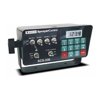
Page 10: Console Features
CONSOLE FEATURES IMPORTANT: IMPORTANT: IMPORTANT: IMPORTANT: IMPORTANT: This Console requires selection of US US US US US (acres), SI SI SI SI SI [hectares], or TU TU TU TU {1,000 sq. ft.} area; SP1 SP1 (wheel drive, etc.) or SP2 SP2 (radar) C-Sd C-Sd... -
Page 11: Console Calibration
CONSOLE CALIBRATION CALCULATING "BOOM CAL" Broadcast Spraying: Calculate the width of each boom in inches [cm] by multiplying the number of tips times the spacing. Write these boom widths down for future reference when programming the Console. FIGURE 7 Band Spraying: Calculate the width of each boom in inches [cm] by multiplying the number of tips by the spacing. -
Page 12: Calculating "Speed Cal
CALCULATION OF RADAR "SPEED CAL" NOTE: NOTE: NOTE: NOTE: NOTE: Numbers in brackets [ ] are metric equivalents. Reset Console according to the instruction manual. Complete "INITIAL CONSOLE PROGRAMMING" in the Installation and Service Manual for your Console. Select SP2 for correct operation of radar. If your Console does not have SP1/SP2 select, you must either update your Console's program, or use a radar adapter (P/N 063-0159-590). -
Page 13: Calculating "Meter Cal
CALCULATING "METER CAL" The Flow Meter calibration number is stamped on the tag attached to each Flow Meter. Write down this number for future reference when programming the Console computer. To convert original METER CAL from gallons to desired units of measure (oz, lbs, or liters per area), see METER CAL CONVERSIONS. -
Page 14: Calculating "Rate Cal
CALCULATING "RATE CAL" Determine the application rate at which your chemical should be sprayed. Consult with your Dealer to ensure your spray nozzles are capable of applying at this rate. In determining which spray nozzles to use with your sprayer, you must know: Nominal Application Pressure ___ PSI [kpa] Target Application Rate... -
Page 15: Console Programming
CONSOLE PROGRAMMING When entering data into the Console, the entry sequence is always the same. NOTE: DATA MUST BE ENTERED INTO KEYS 1 THRU 6. Depress the key in which Depress the ENTER key. you wish to enter data. "E" will illuminate in the DATA display. -
Page 16: Initial Console Programming
INITIAL CONSOLE PROGRAMMING When you first turn on Console power after all installation procedures have been completed, the Console will display "US" in the display window. This means you must "calibrate", or program, the Console before it can be operated. This is a one-time operation which does not have to be repeated. - Page 17 Display C-Sd (Standard Valve), or C-FC (Fast Close Valve). Depressing momentarily steps the display from C-Sd to C-FC. Depressing momentarily steps the display from C-FC to C-Sd. Selecting C-Sd or C-FC. To select C-Sd or C-FC, step until desired code is displayed. Momentarily depress , the display will now show "CAL".
-
Page 18: Other Display Features
OTHER DISPLAY FEATURES See Appendix 9 for detailed outline of each Console key and what features are located under them. To display the set operating modes for units of measure (US, SI, TU), speed sensor type (SP1, SP2), and valve type (C-Sd, C-FC), depress for 5 seconds and continue holding. -
Page 19: Self Test Feature
SELF TEST FEATURE SELF TEST allows speed simulation for testing the system while the vehicle is not moving. Enter the simulated operating speed by depressing the key labelled for 5 seconds. Display will show "-tESt-". If 6 MPH [9.6 km/h] is desired, enter 6.0 [9.6] (See CONSOLE PROGRAMMING). -
Page 20: Automatic Rate
AUTOMATIC RATE +/- This feature sets the increment at which flow is increased or decreased in the AUTO mode of operation. Select RATE +/- for product by depressing for 7 seconds. The display will show "dELt". Enter the desired amount for +/-. EXAMPLE: EXAMPLE: EXAMPLE:... -
Page 21: Valve Cal
VALVE CAL To display current VALVE CAL setting, depress dey labled for 5 seconds. VALVE CAL number will show in DATA display. Control Valve 10. CONTROL VALVE DELAY Delay Digit X 0 0 0 Depress key labelled for 5 seconds. "dLAY"... -
Page 22: 13. Enter Mode Sequence With Activated Data-Lock
13. ENTER MODE SEQUENCE WITH ACTIVATED DATA-LOCK Depress the Console key that you wish to enter data into and depress "codE" message will appear in the display. Enter your activated code number and depress . If code is correct, "E" will appear in display and Console will allow data entry, If code is incorrect, Console will cancel out of requested key. -
Page 23: Initial System Field Test
INITIAL SYSTEM FIELD TEST Drive down field or road at target speed with sprayer booms OFF, to verify SPEED readout on Console. Turn MASTER switch and BOOM switches to ON. Place the OFF/MAN/AUTO switch to AUTO. Increase or decrease speed by one MPH [2 km/h]. The system should automatically correct to the target application rate. -
Page 24: Appendixes
APPENDIX 1 WHEEL DRIVE SPEED SENSOR INSTALLATION AND CALIBRATION PROCEDURE MOUNTING WHEEL DRIVE SPEED SENSOR The Wheel Drive Speed Sensor consists of two magnets, a switch assembly with cable, and mounting hardware. Sequence of mounting Speed Sensor: Select a non-driven wheel (left front tractor wheel or implement wheel). Check for predrilled holes in rim. - Page 25 RIM DRILLING INSTRUCTIONS FOR WHEEL DRIVE SPEED SENSOR MAGNETS On wheels which do not have pre-punched mounting holes, proceed as follows: NOTE: NOTE: NOTE: If only two magnets are to be mounted; drill two holes 180° from each NOTE: NOTE: other.
- Page 26 CALCULATING "SPEED CAL" Place a chalk mark or tape onto the vehicle tire that the Speed Sensor mounted to it as shown below. Mark the initial spot on the ground. Drive vehicle straight ahead counting 10 full revolutions of the wheel. The mark must stop at the same position it was in when the vehicle started.
-
Page 27: Speedometer Drive Speed Sensor Installation And Calibration
APPENDIX 2 SPEEDOMETER DRIVE SPEED SENSOR INSTALLATION AND CALIBRATION PROCEDURE MOUNTING THE SPEEDOMETER DRIVE SPEED SENSOR Remove the existing speedometer cable from the back of the vehicle speedometer. Pull cable through fire wall into engine compartment. Install adapter and key on speedometer cable and connect to Transducer Assembly. (Some units do not use adapter and key). - Page 28 CALCULATING "SPEED CAL" Complete "INITIAL CONSOLE PROGRAMMING" before doing this procedure. Enter “0” in key labelled Enter a SPEED CAL of 306 [78] in key labelled Drive 1 mile [1 km]. CAUTION: CAUTION: CAUTION: CAUTION: CAUTION: Do not use vehicle odometer to determine distance. Use section lines or Highway markers.
-
Page 29: Alternate By-Pass Line Plumbing System
APPENDIX 3 ALTERNATE BY-PASS LINE PLUMBING SYSTEM FIGURE 11 FIGURE 11 FIGURE 11 FIGURE 11 FIGURE 11 INITIAL SYSTEM SET-UP Plumb the system as shown in Figure 11. Adjust as follows: Install Polarity Reversal Jumper in motorized Control Valve Cable (P/N 115-0159-415). Fill tank with water only. - Page 30 Verify that each boom valve operates and that no nozzles are plugged by operating the BOOM ON/OFF switches. Place all BOOM ON/OFF switches to ON. Hold the FLOW CONTROL switch to INC position for approximately 12 seconds. This assures motorized Control Valve is fully closed. (Pressure gauge is not supplied). NOTE: NOTE: NOTE:...
-
Page 31: Procedure To Test Speed Sensor Extension Cables
APPENDIX 4 PROCEDURE TO TEST SPEED SENSOR EXTENSION CABLES Verify that the Console is in the SP1 Speed Sensor mode while testing the cable. Disconnect extension cable from Speed Sensor Assembly cable. Hold extension cable connector so that keyway is pointing in the 12 o’clock position. PIN DESIGNATIONS PIN DESIGNATIONS PIN DESIGNATIONS... -
Page 32: Procedure To Test Flow Meter Cables
APPENDIX 5 PROCEDURE TO TEST FLOW METER CABLES Disconnect cable from Flow Sensor. Hold Flow Sensor cable so that the keyway is pointing in the 12 o’clock position: PIN DESIGNATIONS PIN DESIGNATIONS PIN DESIGNATIONS PIN DESIGNATIONS PIN DESIGNATIONS 2 o’clock socket location is ground. 10 o’clock socket location is power. -
Page 33: Flow Meter Maintenance And Adjustment Procedure
APPENDIX 6 FLOW METER MAINTENANCE AND ADJUSTMENT PROCEDURE Remove Flow Meter from sprayer and flush with clean water to remove any chemicals. NH NH NH NH WARNING: WARNING: WARNING: Thoroughly bleed nurse tank hose and all other system lines prior WARNING: WARNING: 3 3 3 3 3... -
Page 34: Procedure To Re-Calibrate Flow Meter
APPENDIX 7 PROCEDURE TO RE-CALIBRATE FLOW METER Enter a METER CAL number of 10 [38] in the key labelled Enter a TOTAL VOLUME of 0 in the key labelled Switch OFF all booms. Remove a boom hose and place it into a calibrated 5 gallon [19 liter] container. Switch ON appropriate boom switch (for the hose that was just placed into the 5 gallon container) and the MASTER switch. -
Page 35: Remote Switch Option
APPENDIX 8 REMOTE SWITCH OPTION FIGURE 12 FIGURE 12 FIGURE 12 FIGURE 12 FIGURE 12 The REMOTE switch when installed is in parallel the Master switch; therefore or or or or or switching on the REMOTE switch the MASTER switch will energize the boom valves. -
Page 36: Hidden Features
APPENDIX 9 HIDDEN FEATURES The SCS 330 Console is equipped with many hidden features. Several Console keys have multiple features located under them. The amount of time a key is held down determines the feature that will be displayed. The display will flash the coded name of the feature that is being programmed. - Page 37 SCS 330 REPLACEMENT PARTS ITEM ITEM ITEM ITEM ITEM DESCRIPTION DESCRIPTION DESCRIPTION DESCRIPTION DESCRIPTION RAVEN PART # RAVEN PART # RAVEN PART # RAVEN PART # RAVEN PART # Master Switch 412-2011-037 Boom Switch 412-2011-038 Off/Man/Auto Switch 412-2011-052 Inc/Dec Switch...
- Page 39 How Can I Get Service? Bring the defective part and proof of purchase to your Raven Dealer. If your Dealer agrees with the warranty claim, the Dealer will send the part and proof of purchase to their distributor or to Raven Industries for final approval.
- Page 40 P.O. Box 5107 Fax: 605-331-0426 Sioux Falls, SD 57117-5107 www.ravenprecision.com atdinfo@ravenind.com Notice: This document and the information provided are the property of Raven Industries, Inc. and may only be used as authorized by Raven Industries, Inc. All rights reserved under copyright laws.
Need help?
Do you have a question about the SCS-330 and is the answer not in the manual?
Questions and answers
On 6 for flow rate I get code and will not let me change
@Daniel Lenz On 6 I get
What does code mean on scs 330 when I push. Enter