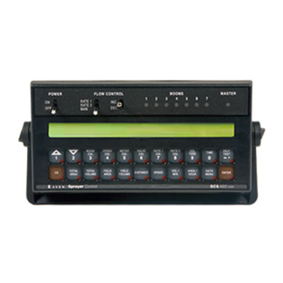
Raven SCS 460 Installation And Service Manual
Sprayer control system
Hide thumbs
Also See for SCS 460:
- Installation & service manual (58 pages) ,
- Operator's manual (47 pages) ,
- Installation manual (28 pages)
Table of Contents
Advertisement
Advertisement
Table of Contents

Related Manuals for Raven SCS 460


Summary of Contents for Raven SCS 460
- Page 1 SCS 460 3 TIER DRIVER INSTALLATION SERVICE MANUAL...
- Page 2 N O T I C E The use of the suspension type fertilizers and lime slurries will significantly reduce the life of the plastic parts in the Flow Meter and motorized Control Valve. Check the rotor and inlet hub assembly in the Flow Meter frequently for worn parts.
- Page 4 Bring the defective part, and proof of date of purchase, to your local dealer. If your dealer agrees with the warranty claim, he will send the part, and proof of purchase to his distributor or to Raven for final approval.
- Page 5 Manual Rev.A, SCS 460 3 Tier Driver 02/02 #016-0159-888...
-
Page 6: Table Of Contents
SYMBOL DEFINITION ......................2 INTRODUCTION ........................3 INSTALLATION ........................4 1. MOUNTING THE RAVEN RADAR SPEED SENSOR .............. 4 2. MOUNTING THE FLOW METER AND PRESSURE TRANSDUCER ........5 3. MOUNTING THE CONTROL VALVE ..................6 4. MOUNTING THE TIER DRIVER INTERFACE BOX ..............6 5. -
Page 7: Symbol Definition
SYMBOL DEFINITION - Gallons per minute - Centimeters lit/min - Liters per minute - Decimeters dl/min - Deciliter per minute - Meter - Pounds per square inch - Miles per hour - Kilopascal - Kilometers - Gallon per acre km/h - Kilometers per hour lit/ha - Liter per hectare... -
Page 8: Introduction
The 3 Tier Driver ability of the SCS 460 will turn on and off different sets of nozzle tiers in order to maintain system pressure as flow increases or decreases. This feature allows for a steady spray pattern. The console will control the tiers through the Tier Driver Interface Box either manually or automatically based on the system pressure. -
Page 9: Installation
INSTALLATION MOUNTING THE RAVEN RADAR SPEED SENSOR See Appendix 1 for Wheel Drive Speed Sensor installation instructions. See Appendix 2 for Speedometer Drive Speed Sensor installation instructions. For mounting the radar, the following guidelines will assure proper installation: It is suggested that a large heavy mounting bracket, (P/N 107-0159-693) be attached to the vehicle frame for mounting the radar. -
Page 10: Mounting The Flow Meter And Pressure Transducer
MOUNTING THE FLOW METER AND PRESSURE TRANSDUCER FLOWMETER Mount Flow Meter in the area of the boom valves per Figure 4. All flow through Flow Meter must go to booms only, i.e., no return line to tank or pump after Flow Meter. Mount Flow Meter horizontal to the ground. -
Page 11: Mounting The Control Valve
MOUNTING THE CONTROL VALVE Mount the motorized Control Valve in the main hose line between the Flow Meter and the booms, with motor in the upright position. (For flow less than 3 GPM [11 lit/min] the motorized Control Valve is mounted in a by-pass line. Refer to Appendix 3 for alternate plumbing diagram). Connect the Flow Control Cable connectors to boom valves, Flow Meter, Pressure Sensor and motorized Control Valve. -
Page 12: Mounting The Console And Cabling
FIGURE 5 NOTE: The SCS 460 Control Console is designed to be used with external boom switches. In order for the Console to know when and which Boom is ON or OFF, boom signal wires are provided. The Console recognizes a boom ON whenever +12 VDC is applied to the boom... -
Page 13: Battery Connections
BATTERY CONNECTIONS FIGURE 6 NOTE: Disconnect 7 Boom Switchbox battery wires if the system is not used for an extended period, (i.e. two weeks). With the POWER switch to OFF, the system draws .25 milliamps of current to maintain information stored in Console computer. -
Page 14: Console Features
CONSOLE FEATURES IMPORTANT: This Console requires selection of US (Volume per acre), SI (Volume per hectare), or TU {1,000 sq. ft.} area; SP1 (wheel drive, etc.) or SP2 (radar) speed sensor; and C-SD (Standard Valve), C-F (Fast Valve), C-FC (Fast Close Valve), C-P (PWM Valve) or C-PC (PWM Close Valve). Hold SELF TEST key to view selections. -
Page 15: Console Calibration
[100] CALCULATING "SPEED CAL" Initial SPEED CAL is 598 [152] when using the Raven radar. Complete Steps 1 thru 6 to refine this number after "INITIAL CONSOLE PROGRAMMING" has been completed. Set POWER switches to ON, all other switches to OFF. -
Page 16: Calculating "Meter Cal
EXAMPLE: Assume DISTANCE reads 5000 [980]. Corrected SPEED CAL Old SPEED CAL x 5280 DISTANCE ENGLISH UNITS: METRIC UNITS: = 598 x 5280 = 631.48 = [152] x [1000] = [155] 5000 [980] The number to enter for SPEED CAL is 631 [155]. Enter the number calculated for SPEED CAL. -
Page 17: Calculating "Valve Cal
CALCULATING "VALVE CAL" The initial recommended Control Valve calibration number for VALVE CAL is 2123 for C-SD (standard valve), 743 C-FC (fast close valve), 743 C-F (fast valve), 43 C-P (PWM valve) or 43 C-PC (PWM close valve). The VALVE CAL number is used to control response time of the control valve motor to the change in vehicle speed. -
Page 18: Calculating "Rate 1 And Rate 2 Cal
CALCULATING "RATE 1 AND RATE 2 CAL" Determine the application rate at which chemical is to be sprayed. Consult with a dealer to ensure these spray nozzles are capable of applying at this rate. In determining which spray nozzles to use with the sprayer the following must be known: 1) Nominal Application Pressure ___ PSI [kpa]... -
Page 19: Console Programming
CONSOLE PROGRAMMING When entering data into the Console, the entry sequence is always the same. NOTE: DATA MUST BE ENTERED FOR ALL BOOMS. ENTER "0" IF BOOM IS NOT USED. DATA MUST ALSO BE ENTERED IN KEYS 3 THRU 8. Depress the ENTER key. - Page 20 NOTE: If an entry selection error is made during steps 1-6, place the power ON/OFF switch to OFF. Depress and hold while placing the power ON/OFF switch to ON. This will reset the console. The display will show CAL US-VOLUME PER ACRE .
- Page 21 Selecting C-SD, C-F, C-FC, C-P or C-PC. To select C-Sd, C-F, C-FC, C-P, or C-PC, press until desired code is displayed. Momentarily depress , the DATA display will now display CAL SELF TEST 00 Definition of Boom Calibration keys. Depressing this key displays selected boom number in display. EXAMPLE: Boom 1 will be displayed as BOOM 1 CAL Depressing this key after selecting BOOM CAL changes the boom number.
- Page 22 ENTERING ADDITIONAL DATA: Data may be entered in the although it is not required for the operation of the system. ENTERING VOLUME: Enter the estimated VOLUME in the TANK in . Each time the tank is refilled, this number must be re-entered. ENTERING TIME, DATE, AND POWER DOWN: Definition of Time, Date, and Power Down Key: Depressing this key displays selected Time.
-
Page 23: Other Display Features
OTHER DISPLAY FEATURES To display TOTAL AREA covered, momentarily depress To "zero out" this total at any time, enter a "0" in this key. To display TOTAL VOLUME sprayed, momentarily depress To "zero out" this total at any time, enter a "0" in this key. To display FIELD AREA covered, momentarily depress To "zero out"... -
Page 24: Volume/Minute Rate Fault
VOLUME/MINUTE RATE FAULT Depress until display shows . A low limit flow rate may now be entered. If the actual SET LOW LIMIT 0 volume per minute falls below this limit, the Control Valve stops closing, an alarm sounds, and the display flashes . -
Page 25: Zero Speed Shut-Off
Rate 1 calibration number is changed via the serial port using a valid change request data string. GPS FILE REF 1 Used only with Raven Grid Application System. See Grid Application System manual for more details. Used only with Raven Grid Application System. See Grid GPS INACTIVE Application System manual for more details. - Page 26 DISPLAY DESCRIPTION DATA LOG TRIGGER UNITS FEET Used in data logging mode. The trigger unit is selectable between feet [meters] or seconds. DATA LOG OFF Turns data logger ON or OFF. Used to set the zero point of the pressure transducer for PRESS ENTER TO CAL PRESSURE pressure display.
- Page 27 Definition of Data Menu Key: Depressing this key displays selected Data Menu features. EXAMPLE: Display will display options by name and default setting. Depressing this key after selecting DATA MENU increments up through desired features. EXAMPLE: PRINT FIELD BEGIN ALARM ON DISPLAY SMOOTHING ON etc.
- Page 28 GPS FILE REFERENCE Display will show GPS FILE REF 1 Enter the GPS file number Momentarily depress to advance to GPS OPTIONS. GPS OPTIONS GPS is inactive when the display shows GPS INACTIVE The GPS features are explained further in the GRID APPLICATION SYSTEM MANUAL. Momentarily depress to advance to FIELD REFERENCE.
- Page 29 DATA LOGGER ON/OFF The DATA LOGGER uses the communications strings listed in Appendix 9 to pass data out through the serial port. The data is sent at a set time interval or a set distance traveled, as determined by the values entered in the DATA LOGGER TRIGGER VALUE and DATA LOGGER TRIGGER UNITS.
- Page 30 HIGH PWM OFFSET 253 Used to set the maximum desired RPM or hydraulic output of control valve. Display will show HIGH PWM OFFSET 253 Place product switch on MAN, boom switches and master switch ON. Hold INC/DEC switch to increase. If motor exceeds desired RPM, decrease number by 10 and push INC again. Decrease the 253 number displayed until motor runs at desired maximum RPM, then enter a number of 10 more.
- Page 31 MAXIMUM SYSTEM PRESSURE 60 Display will show MAXIMUM SYSTEM PRESSURE 60 Press . Enter the maximum pressure for the system (i.e. 65 PSI). Press , depress again. Momentarily depress to advance to DATA LOCK (console skips TIER A ONLY when in automatic mode). TIER A ONLY Display will show TIER A ONLY...
-
Page 32: 11. Decimal Shift
11. DECIMAL SHIFT The DECIMAL SHIFT feature is used to increase system accuracy at low application rates. Shifting of the decimal point is done during the entry of METER CAL. After entering METER CAL mode, depress the decimal shift , enter the meter calibration constant number, and depress The sequence to unshift the decimals while in METER CAL is to enter the meter calibration constant number and depress . -
Page 33: Initial System Set-Up
INITIAL SYSTEM SET-UP Fill tank with water only. (If positive displacement pump is used, open pressure relief valve, PRV). Place MASTER ON/OFF switch to ON and BOOM ON/OFF switches to OFF. Place RATE 1/RATE 2/MAN switch to MAN. Place POWER ON/OFF switch to ON. Verify that Boom Widths, SPEED CAL, METER CAL, VALVE CAL, and RATE CALS have been entered correctly into the Console. -
Page 34: Initial System Field Test
INITIAL SYSTEM FIELD TEST Drive down field or road at target speed with sprayer booms off, to verify SPEED readout on Console. Turn on sprayer and booms and place the RATE 1/RATE 2/MAN switch to RATE 1. Increase or decrease speed by one MPH [2 km/h]. The system should automatically correct to the target application rate. -
Page 35: Troubleshooting Guide
TROUBLESHOOTING GUIDE PROBLEM CORRECTIVE ACTION NO DISPLAY LIGHTS WITH POWER ON. Check fuse on back of Console. Check battery connections. Check operation of POWER ON/OFF switch. Return Console to your Dealer to replace Processor Board Assembly. ALL KEYBOARD LIGHTS ON AT SAME Return Console to your dealer to replace TIME. - Page 36 Remove one red magnet and one black magnet from the wheel. (Reposition remain- ing red and black magnets directly across from each other). Enter a SPEED CAL num- ber in the Console twice as large as the correct SPEED CAL number. Run speed check on hard surface road.
- Page 37 CANNOT VARY RATE IN MANUAL Check cabling to motorized Control Valve for OPERATION OR IN AUTO. breaks. Check connections in cabling for cleanli- ness. Verify that there is voltage at the valve con- nector by placing MASTER switch ON; RATE 1/RATE 2/MAN switch to MAN; and POWER switch to ON.
-
Page 38: Appendixes
APPENDIX 1 WHEEL DRIVE SPEED SENSOR INSTALLATION AND CALIBRATION PROCEDURE MOUNTING WHEEL DRIVE SPEED SENSOR The Wheel Drive Speed Sensor consists of four magnets, a switch assembly with cable, and mounting hardware. Sequence of mounting Speed Sensor: Select a non-driven wheel (left front tractor wheel or implement wheel). Check for predrilled holes in rim. - Page 39 RIM DRILLING INSTRUCTIONS FOR WHEEL DRIVE SPEED SENSOR MAGNETS On wheels which do not have pre-punched mounting holes, proceed as follows: RIMS WITH FOUR OR EIGHT HOLE STUD PATTERN: Choose stud holes that are opposite each other as shown below. Using the center of opposite holes, scribe two lines on the rim web to divide the circumference into four equal parts.
- Page 40 CALCULATING "SPEED CAL" Place a chalk mark or tape onto the vehicle tire that the Speed Sensor mounted to it as shown below. Mark the initial spot on the ground. Drive vehicle straight ahead counting 10 full revolutions of the wheel. The mark must stop at the same position it was in when the vehicle started.
-
Page 41: Speedometer Drive Speed Sensor Installation And Calibration
APPENDIX 2 SPEEDOMETER DRIVE SPEED SENSOR INSTALLATION AND CALIBRATION PROCEDURE MOUNTING THE SPEEDOMETER DRIVE SPEED SENSOR Remove the existing speedometer cable from the back of the vehicle speedometer. Pull cable through fire wall into engine compartment. Install adapter and key on speedometer cable and connect to Transducer Assembly. (Some units do not use adapter and key). - Page 42 CALCULATING "SPEED CAL" Complete "INITIAL CONSOLE PROGRAMMING" before doing this procedure. Enter “0” in key labelled Enter a SPEED CAL of 612 [155] in key labelled Drive 1 mile [1 km]. CAUTION: Do not use vehicle odometer to determine distance. Use section lines or Highway markers.
-
Page 43: Alternate By-Pass Line Plumbing System
APPENDIX 3 ALTERNATE BY-PASS LINE PLUMBING SYSTEM FIGURE 11 INITIAL SYSTEM SET-UP Plumb the system as shown in Figure 11. Adjust as follows: Install Polarity Reversal Jumper in motorized Control Valve Cable (P/N 115-0159-415). Fill tank with water only. Place MASTER ON/OFF switch to ON and BOOM ON/OFF switches to OFF. Place AUTO/MAN/OFF switch to MAN, and POWER ON/OFF to ON. - Page 44 Verify that each boom valve operates and that no nozzles are plugged by operating the BOOM ON/ OFF switches. Place all BOOM ON/OFF switches to ON. Hold the FLOW CONTROL switch to INC position for approximately 12 seconds. This assures motorized Control Valve is fully closed.
-
Page 45: Procedure To Test Speed Sensor Extension Cables
APPENDIX 4 PROCEDURE TO TEST SPEED SENSOR EXTENSION CABLES Verify that the Console is in the SP1 Speed Sensor mode while testing the cable. Disconnect extension cable from Speed Sensor Assembly cable. Hold extension cable connector so that keyway is pointing in the 12 o’clock position. PIN DESIGNATIONS 2 o’clock socket location is power. -
Page 46: Procedure To Test Flow Meter Cables
APPENDIX 5 PROCEDURE TO TEST FLOW METER CABLES Disconnect cable from Flow Sensor. Hold Flow Sensor cable so that the keyway is pointing in the 12 o’clock position: PIN DESIGNATIONS 2 o’clock socket location is ground. 10 o’clock socket location is power. 6 o’clock socket location is signal. -
Page 47: Flow Meter Maintenance And Adjustment Procedure
APPENDIX 6 FLOW METER MAINTENANCE AND ADJUSTMENT PROCEDURE Remove Flow Meter from sprayer and flush with clean water to remove any chemicals. WARNING: Thoroughly bleed nurse tank hose and all other system lines prior to disassembling the Flow Meter, fittings, and hoses. Remove flange bolts or clamp from the Flow Meter. -
Page 48: Procedure To Re-Calibrate Flow Meter
APPENDIX 7 PROCEDURE TO RE-CALIBRATE FLOW METER Enter a METER CAL number of 10 [38] in the key labelled Enter a TOTAL VOLUME of 0 in the key labelled Switch OFF all booms. Remove a boom hose and place it into a calibrated 5 gallon [19 liter] container. Switch ON appropriate boom switch (for the hose that was just placed into the 5 gallon container) and the MASTER switch. -
Page 49: Serial Interface
Communication Carriage Return string RATE 1 Rate Cal = 123.4 Decimal point is not sent from Remote Computer to Raven Console. ) Optional 9 pin to 9 pin cable pinout (P/N 115-0159-822). DSR 6 CTS 8 RAVEN COMPUTER/ DTR 4... -
Page 50: Scs 460 Communication Strings
SCS 450/460 CONSOLE TO REMOTE COMPUTER All console output strings begin with $R124F, the $R indicates a Raven communication string, the 124 is the last three digits of the current SCS 450/460 programmed chip part number and F is the software revision number.
Need help?
Do you have a question about the SCS 460 and is the answer not in the manual?
Questions and answers