Raven Viper Pro Quick Reference Manual
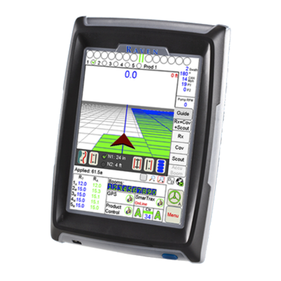
Field computer
Hide thumbs
Also See for Viper Pro:
- Installation & operation manual (300 pages) ,
- Update manual (12 pages)
Table of Contents
Advertisement
Advertisement
Table of Contents

Related Manuals for Raven Viper Pro


Summary of Contents for Raven Viper Pro
-
Page 1: Quick Reference Guide
Quick Reference Guide Viper Pro™ Software Version 3.10... - Page 2 Don’t turn Viper Pro off when in a job without properly closing the job first. If the field computer loses power when in a job, part of the information within the job files will not be saved and the associated files may become corrupt.
-
Page 3: Backlight Adjustment
- The current speed of the vehicle (CAN or GPS). Map Area - The map area displays information based on the selected tab. Touch the tabs along the right side of the Viper Pro display to view application information, maps, or guidance information. Tabs - Used to access available features, functions and screen displays during a job. - Page 4 GPS information. Product Control Status - Product Control Status of a Raven serial console or a Raven CAN system displays in this area. Touch this area to view or modify Product Control settings. SmarTrax Status Display - If an optional SmarTrax system is installed with the Viper Pro, this area displays the status of SmarTrax system.
-
Page 5: Status Symbols
Controller Status screen areas. Note: The CAN Controller Status screen shown above is only displayed if the Viper Pro is configured as the CANbus control console. Review the Viper Pro Installation and Operation Manual for information on configuring the field computer. -
Page 6: Application Area
Product Control Settings Area - Displays the current product control settings for the selected product node or control channel. Touch in this area to configure product control for the selected node or channel. Pressure Area - Dual pressure readouts for two different systems. Touch in this area to calibrate pressure readouts. - Page 7 2. Select a profile from the list and touch OK. 3. Touch the OK button on the Load Profile prompt. The Shutdown Viper prompt will be displayed. 4. Select the Exit to Menu button and select the appropriate option to restart the Viper Pro application management system.
- Page 8 3. Enter Target Rate. Touch Next to change other Nodes or OK to save changes and close. Note: Application Rates may only be modified on the Viper Pro if the field computer is set as the CANbus controller. Product density and spreader constant may also be modified when controlling a granular application system.
- Page 9 Starting a New AgX Job 1. Select Menu, Start Job, then New AgX Job. 2. Select from the available grower, farm and field lists to locate the prepopulated job information for the next job.
- Page 10 3. Touch the Next button. 4. Touch an available control channel and select a recommendation from the list to assign prepopulated job information to the selected control channel. Note: While recommendations are not required, product control channels selected on this screen should have a recommendation assigned before the job is started.
- Page 11 Starting a New Standard Job 1. Select Menu, Start Job, then New Job. 2. Type in a Job Name, and enable appropriate application options to use during the job. Select a Swath Pattern (if guidance is enabled), and enter the number of products (if product application is enabled).
- Page 12 4. Select an existing product name or use the on-screen keyboard to enter a new product name. 5. If a Variable Rate map will be used, select VRC and proceed with the steps below. Otherwise, touch OK. a. Touch Browse to find an Rx Map file. b.
- Page 13 2. Select an Existing Job and touch OK. Then touch Menu and the Cont. Job button to resume application within the job. Note: The Viper Pro will not log application or location information until the Cont. Job button is selected.
- Page 14 Guidance (A-B) Lines Use the following steps to set an A-B Line. 1. With the Guide tab selected, touch the Set A button. An A-B Line may also be set by entering a compass heading. Touch the Set B by Heading icon at the bottom of the guidance display to enter an A-B Line heading.
- Page 15 Resetting Tank Volume 1. Touch Product Control. 2. Touch Tally Registers. 3. To reset all tank volumes to the previously entered values, touch Reset above Tnk Vol. 4. To reset individual nodes, touch Next. 5. On the Odometer screen, touch Next. 6.
- Page 16 Marking a Field Boundary 1. Touch the Scout tab and then the Record button. 2. Select Zone from the list of features. 3. The Record Field Feature screen displays. Select Field Boundary and select the point entry and offset your options, and touch OK. Note: The Field Boundary will automatically close if the machine comes within one boom width of the starting point.
- Page 17 1. Select Menu, Setup, and Comm Ports. 2. Select the appropriate GPS setting. • Select Raven GPS when connected to all Raven GPS receivers, except for the RPR 400, RPR 410, and the Phoenix 300, or when not using the guidance in the Viper Pro to control a SmarTrax/SmartSteer system.
- Page 18 The aggressiveness factor setting uses a percentage of the look-ahead times to adjust the responsiveness of the AccuBoom system. If a SwitchPro is connected to the Viper Pro, AccuBoom control is controlled by the switch position on the Switch Box. Review the SwitchPro...
- Page 19 AutoBoom Calibration UltraGlide 1. Touch in the center of the AutoBoom Area. 2. Select AutoBoom ON and UltraGlide for mode. 3. Touch the Calibrate button. 4. Touch Cal Left and wait for left boom calibration to complete, then touch Cal Right and wait for right boom calibration to complete.
- Page 20 PowerGlide Plus 1. Touch in the center of the AutoBoom Area. 2. Select AutoBoom ON and PowerGlide Plus for mode. 3. Touch the Calibrate button. Note: The AutoBoom Control screen in PowerGlide Plus mode will appear similar to the screens shown in the previous UltraGlide section. Refer to the UltraGlide section to locate the ON and Calibrate buttons if necessary.
- Page 21 On-Screen Lightbar 1. Touch Menu, Setup, then Lightbar. 2. Select a Lightbar to use. 3. Select Send Guidance Message, when using the Viper Pro to provide guidance information to a SmarTrax/SmartSteer system. 4. Touch Next to set it up. 5. Touch OK when finished.
- Page 22 Viper Pro Menu Structure * Buttons with arrows go to sub-menus. Buttons without arrows go directly to selection screens.
- Page 24 Notice: This document and the information provided are the property of Raven Industries, Inc. and may only be used as authorized by Raven Industries, Inc. All rights reserved under copyright laws. ©Raven Industries, Inc. 2007, 2008, 2009, 2011, 2012, 2013, 2014...
Need help?
Do you have a question about the Viper Pro and is the answer not in the manual?
Questions and answers