Intel S7000FC4UR Technical Product Specification
Hide thumbs
Also See for S7000FC4UR:
- Product manual (232 pages) ,
- Manual (13 pages) ,
- Configuration manual (13 pages)

Related Manuals for Intel S7000FC4UR


Summary of Contents for Intel S7000FC4UR
- Page 1 Intel® Server System S7000FC4UR Technical Product Specification E18291-001 Intel order number Revision 1.0 July 13, 2007 Enterprise Platforms and Services Division - Marketing...
-
Page 2: Revision History
Intel products are not intended for use in medical, life saving, or life sustaining applications. Intel may make changes to specifications and product descriptions at any time, without notice. -
Page 3: Table Of Contents
2.1.1 Main Board Block Diagram ..................2 Functional Architecture .................... 4 2.2.1 Intel® Xeon® Processors ..................4 2.2.2 Intel® 7300 Chipset Memory Controller Hub ............5 2.2.3 Enterprise Southbridge 2 ..................6 2.2.4 PCI-Express* Subsystem ..................7 2.2.5 PCI 32-Bit Subsystem.................... 10 2.2.6... - Page 4 Table of Contents Intel® Server System S7000FC4UR Functional Architecture ..................33 3.2.1 I/O Riser / Server Management Diagram............... 34 3.2.2 SMBus Block Diagram................... 35 3.2.3 Hardware Monitoring Block Diagram ..............36 3.2.4 Sensor Data Record SDR (SDR) Repository............37 3.2.5 Field Replaceable Unit (FRU) Inventory Devices ..........
- Page 5 User-Accessible Connectors, PCI Slots and LEDs..........72 8.2.2 Power Distribution Board (PDB) ................73 8.2.3 Front Panel I/O Board.................... 73 8.2.4 Front Panel Control Board ..................73 8.2.5 SATA-to-PATA Converter Board ................73 8.2.6 Intel® Remote Management Module 2 (Intel® RMM2).......... 73 Revision 1.0...
- Page 6 Table of Contents Intel® Server System S7000FC4UR Power Subsystem....................73 Cooling Subsystem....................74 Specifications......................75 8.5.1 Environmental Specifications................. 75 8.5.2 Physical Specifications ..................75 9. System Chassis and Sub-Assemblies................77 Base Chassis and Top Covers ................77 9.1.1 Base Chassis......................77 9.1.2...
- Page 7 Intel® Server System S7000FC4UR Table of Contents 10.2.8 C Devices ......................88 10.2.9 Power Supply Module LED indicators ..............89 10.3 Regulatory Agency Requirements ................. 89 11. Power Distribution Board ....................90 11.1.1 Remote On/Off (-PS_ON) ..................90 11.1.2 POWER GOOD SIGNAL (POK, or P_GOOD)............90 11.1.3...
- Page 8 Table of Contents Intel® Server System S7000FC4UR 14.1.10 Hardware Prefetch....................100 14.1.11 Adjacent Cache Line Prefetch ................100 ® 14.1.12 Intel Core Multi-Processing (CMP)..............101 ® 14.1.13 Intel Virtualization Technology ................101 14.1.14 “Fake MSI” Support ..................... 102 14.1.15 Direct Cache Access (DCA) ................103 14.1.16 Snoop Filter ......................
- Page 9 Intel® Server System S7000FC4UR Table of Contents 14.3.10 Flash ROM......................147 14.4 Fan Speed Control and Thermal Management ........... 148 14.4.1 FBDIMM Thermal Management................148 14.4.2 Processor Thermal Management ................ 150 15. BIOS User Interface......................151 15.1 Splash Logo / Diagnostic Screen................. 151 15.1.1...
- Page 10 Table of Contents Intel® Server System S7000FC4UR 17.4.2 Supported Wake Events ..................201 17.5 Non-Maskable Interrupt (NMI) Handling .............. 202 18. BIOS Role in Server Management................... 204 18.1 IPMI ........................204 18.2 Console Redirection .................... 204 18.2.1 Keystroke Mappings .................... 205 18.2.2...
- Page 11 Intel® Server System S7000FC4UR Table of Contents 19.3 POST Progress Codes and Errors ..............235 19.3.1 POST Error Beep Codes ..................235 19.3.2 POST Codes......................235 19.3.3 POST Error Manager Messages and Handling ........... 238 20. New Technologies......................247 ®...
- Page 12 Table of Contents Intel® Server System S7000FC4UR 22.3.6 Watchdog Timer Expiration ................. 257 22.4 BMC Reset Control ....................257 22.4.1 BMC Exits Firmware Update Mode..............257 22.4.2 Standby Power Comes Up .................. 257 22.5 System Initialization ..................... 257 22.5.1 Processor TControl Setting.................. 257 22.5.2...
- Page 13 Field Replaceable Unit (FRU) / Fault LED Control ..........276 22.23 Hot-Swap Controller .................... 277 22.23.1 Backplane Types ....................277 22.24 Intel® Remote Management Module 2 (Intel® RMM2)........277 22.25 Memory Region Temperature Monitoring ............278 22.25.1 DIMM Temperature Monitoring ................278 22.25.2 Memory Riser Board Temperature Monitoring............. 278 22.26...
- Page 14 Table of Contents Intel® Server System S7000FC4UR 23.3.1 COM Port Switching .................... 281 23.3.2 Terminal Mode..................... 281 23.3.3 Invalid Passwords....................282 23.4 LAN Interface....................... 282 23.4.1 IPMI 1.5 Messaging ..................... 282 23.4.2 ESB2 Embedded LAN Channels ................. 283 23.4.3 Address Resolution Protocol (ARP)..............283 23.4.4...
- Page 15 Intel® Server System S7000FC4UR List of Figures 29.6 Temperature Monitoring ..................305 29.7 Disk Management....................305 29.7.1 Drive Fault Light Control ..................305 29.7.2 Drive Presence Detection ..................305 29.7.3 Enclosure Temperature Sensing ................. 306 29.8 Slot Status to Fault Light State Mapping ............. 306 30.
- Page 16 Server System S7000FC4UR (Front View)............68 ® Figure 19. Intel Server System S7000FC4UR (rear view with top cover removed) ....69 Figure 20. Front View (without bezel) ..................70 Figure 21. Rear View ........................72 Figure 22. Slide Rail Mounting Features..................78 Figure 23.
- Page 17 Figure 59. Setup Utility — Console Redirection Screen Display ..........182 Figure 60. Setup Utility — Server Management System Information Screen Display ....183 ® Figure 61. Setup Utility — Intel Remote Management Module Information Screen Display ... 184 Figure 62. Setup Utility — Boot Options Screen Display ............185 Figure 63.
- Page 18 List of Tables Intel® Server System S7000FC4UR Table 4. IDSEL Mapping......................11 Table 5. Arbitration Connections....................11 Table 6. Binary Code Definition ....................18 Table 7. POST Code LED Definition................... 19 Table 8. Thermal Specifications....................30 Table 9. FRU Device Location and Size ..................37 Table 10.
- Page 19 Table 57. Setup Utility — Console Redirection Configuration Fields........182 Table 58. Setup Utility — Server Management System Information Fields ......183 ® Table 59. Setup Utility — Intel Remote Management Module Information Fields....184 Table 60. Setup Utility — Boot Options Screen Fields ............. 185 Table 61.
- Page 20 List of Tables Intel® Server System S7000FC4UR Table 74. SMBIOS Type 1 Structure — System Information ............ 211 Table 75. SMBIOS Type 4 Structure — Processor Information..........212 Table 76. SMBIOS Type 7 Structure — Cache Information............214 Table 77. SMBIOS Type 11 Structure — OEM Strings............. 216 Table 78.
- Page 21 Intel® Server System S7000FC4UR List of Tables Table 109. Slot Status to Fault Light State Mapping..............306 Table 110. HSC Sensor / Event Message Source Numbers ............ 307 Table 111. Sensor Formats ...................... 309 Revision 1.0...
-
Page 23: Introduction
Intel® Server System S7000FC4UR TPS Introduction Introduction ® This document details the technical specifications of the Intel Server System S7000FC4UR. This document is organized into the following sections: Section 1, Introduction: An overview of this document. Sections 2-3, Baseboard: Describes the specifications, features and functions of the baseboard. -
Page 24: Main Board
Main Board Intel® Server System S7000FC4UR TPS Main Board ® This chapter describes the main board for the Intel Server System S7000FC4UR. Introduction The main board provides most of the basic functions for the system. Nearly all of the boards from the boardset plug into or cable to the main board. -
Page 25: Figure 1. Main Board Block Diagram
Intel® Server System S7000FC4UR TPS Main Board Figure 1. Main Board Block Diagram Revision 1.0... -
Page 26: Functional Architecture
The main board supports the Quad-Core Intel Xeon Processors 7300 Series or Dual-Core ® Intel Xeon Processors 7200 Series, which are based on the low-power next-generation Intel Core™ micro-architecture. Several architectural and micro architectural enhancements have been added to this processor, including multiple processor cores. ®... -
Page 27: Intel® 7300 Chipset Memory Controller Hub
7300 Chipset Memory Controller Hub is the center of the Intel Server System S7000FC4UR architecture. This chipset is designed for multi-core processors and includes the advanced features detailed in the following bullets. For more detailed information, refer to the ®... -
Page 28: Enterprise Southbridge 2
Enterprise Southbridge 2 that are used in the main board are as follows: Integrated Serial ATA (SATA) controller PCI 32-bit / 33MHz interface ® Five USB 2.0 ports (1 Front Panel, 2 Rear Panel, 1 Internal, 1 to Intel Remote Management Module 2) Low Pin Count (LPC) Interface... -
Page 29: Pci-Express* Subsystem
Intel® Server System S7000FC4UR TPS Main Board ® Intel I/OAT enabled x4 link to MCH ESI x4 Link to MCH Two downstream PCI-Express* x4 links Four downstream PCI-Express* x1 links configured as a one x4 link 24 bit expansion bus for BMC memory devices... - Page 30 ® The PCI-Express* Expander/Switch IDT 89HPES24N3A works in conjunction with the Intel 7300 Chipset. It utilizes a single x8 PCI-Express* upstream bus and expands it into two unique downstream x8 PCI-Express* buses. Some features of the PCI-Express* Expander used on the main board are as follows: 24 PCI Express* lanes (2.5 Gbps), three switch ports...
- Page 31 Intel® Server System S7000FC4UR TPS Main Board Utilizes advanced low-power design techniques to achieve low typical power consumption Support PCI Express* Power Management Interface Specification (PCI-PM 1.1) Unused SerDes are disabled. Supports Advanced Configuration and Power Interface Specification, Revision 2.0 (ACPI) supporting-active link state 2.2.4.3...
-
Page 32: Pci 32-Bit Subsystem
Main Board Intel® Server System S7000FC4UR TPS 2.2.4.4.1 PCI-Express* Hot-plug Power Controller The main board uses the Texas Instruments* TPS2363 hot-plug controller. The Texas Instruments* TPS2363 is a dual slot PCI-Express* hot plug controller providing support for 12V, 3.3V and 3.3Vaux power control. This support includes the following:... -
Page 33: Main Board Memory Interface
Intel® Server System S7000FC4UR TPS Main Board Table 3 describes how the interrupts for each of the PCI devices are mapped to the Enterprise Southbridge 2. Table 3. PCI Interrupt Mapping Enterprise Southbridge 2 PCI Host Bridge Device INTA# INTB#... -
Page 34: Main Board I/O Riser Interface
One USB port A video DVO interface A LPC Bus A RS232 BMC Serial Bus ® It also has the PCI-Express x4 Link and Gigabit Lan Link for the Intel 82575EB Gigabit Ethernet Controller. 2.2.8 Main Board SAS Riser Interface The main board includes a 98 pin x8 pin PCI-Express* connector to interface with the x4 PCI- Express* SAS Riser card. -
Page 35: Figure 2. Main Board Clock Block Diagram
Intel® Server System S7000FC4UR TPS Main Board S7000FC4UR Server Clock Diagram Rev 2.1 FBD_DIMMA1_CLK_P/N DIF_1P/N 1/26/07 FBD_DIMMA2_CLK_P/N DB1200G_BCLK_P/N DIF_2P/N FBD_DIMMA3_CLK_P/N XDP1 (CPUs) XDP1_BCLK_P/N CPU_0P/N DIF_3P/N BCLK0/1 FBD_DIMMA4_CLK_P/N DIF_4P/N CLK_INP/N DIF_5P/N FBD_DIMMA5_CLK_P/N CPU1_BCLK_P/N DIF_5P/N CPU1 FBD_DIMMA6_CLK_P/N DIF_11P/N DIF_0P/N BCLK0/1 DIF_6P/N DIF_10P/N... - Page 36 Main Board Intel® Server System S7000FC4UR TPS The CK410B supports SSC (Spread Spectrum Clocking), but only for FSB host clocks and SRCs (Serial Reference Clocks). The CK410B supplies the following: Four host clocks Five 100 MHz differential SRCs (Serial Reference Clocks)
- Page 37 SRC input from CK410B Seven SRC differential pairs to seven PCI-Express* slots ® Five SRC differential pairs to I/O Riser (only one used by Intel 82575EB Gigabit Ethernet Controller LOM, four are dedicated for OEM I/O riser) One SRC differential pair to SAS Riser...
-
Page 38: Serial-Ata (Sata) Sub-System
Main Board Intel® Server System S7000FC4UR TPS Note: FBD reference clock routing requires clock-to-clock length matching between FBD agents that are directly connected to each other (i.e. MCH-DIMM1, DIMM1-DIMM2, etc) to within five inches. PCI-Express* SRC does not have any clock-to-clock length matching requirements. -
Page 39: Flash Devices
Resolutions from VGA up to UXGA (1600x1200) 32MB Samsung* K4N56163QG-ZC2A DDRII Video Memory ® Digital Video Input/Output (DVI/DVO) interface goes to Intel Remote Management Module 2 board for KVM support up to 165 MHZ 3.3V 32-bit / 33MHz PCI host interface 2.2.12.2... -
Page 40: Serial Port Support
Gigabit Ethernet PHY through a high-speed serial interface called Kumeran. ® The Kumeran interface consists of two sets of Tx/Rx pairs for a total of eight signals. Intel 82563EB Gigabit Ethernet PHY outputs two Gbit LAN ports and will connect to a 1x2 RJ45 Gbit connector accessible at the rear of the chassis. -
Page 41: Programmable Logic Devices (Plds)
Intel® Server System S7000FC4UR TPS Main Board The Post LEDs are situated as shown in the below table along with the corresponding reference designators. Table 7. POST Code LED Definition Post Code Bit LED Reference Designator POST Code LEDs 7 (MSB) - Page 42 Main Board Intel® Server System S7000FC4UR TPS After CPU and VTT VRs are enabled, as well as any memory riser presence signal asserted, a global VR enable is asserted for memory risers, SAS backpanel, and SAS Riser. An additional output for IO Riser power enable will be asserted at the same time as the other adapters in the system.
- Page 43 Intel® Server System S7000FC4UR TPS Main Board (One supply present AND ((CB_Type=Japan/Brazil AND Util = 74%) OR (CB_Type = Not Japan/Brazil) AND Util = 90%)) Normal operation mode occurs when a single power supply or both power supplies are present (redundant mode) and functioning.
-
Page 44: Interrupt And Error Logic Block Diagram
Main Board Intel® Server System S7000FC4UR TPS 2.2.19 Interrupt and Error Logic Block Diagram Figure 3. Interrupt and Error Logic Block Diagram Revision 1.0 Intel order number E18291-001... -
Page 45: Circuit Breaker Type Jumper
Intel® Server System S7000FC4UR TPS Main Board 2.2.20 Circuit Breaker Type Jumper Jumper J6F1 is used to set a threshold for power consumption when operating the server with a single power supply on a low-line 100/110/115/120/127VAC power circuit. This threshold is required to ensure the power consumption of the server does not exceed the power that can be supplied by a single AC power circuit. -
Page 46: Power Delivery Block Diagram
Main Board Intel® Server System S7000FC4UR TPS If the jumper is covering pins 1-2 on a 100/110VAC circuit, the server is allowed to consume up to 1180 watts. This setting may cause a circuit breaker to trip. If the jumper is covering pins 2-3 on a 115/120/127VAC circuit, the server power consumption threshold is set to 1030 watts. -
Page 47: Figure 4. Main Board Power Block Diagram
Intel® Server System S7000FC4UR TPS Main Board Figure 4. Main board Power Block Diagram Revision 1.0... -
Page 48: Reset And Powergood Diagram
Main Board Intel® Server System S7000FC4UR TPS 2.2.22 Reset and Powergood Diagram Figure 5. Main Board Reset and Powergood Block Diagram Revision 1.0 Intel order number E18291-001... -
Page 49: Power Sequencing/Timing Diagrams
Intel® Server System S7000FC4UR TPS Main Board 2.2.23 Power Sequencing/Timing Diagrams 2.2.23.1 Power-Up Sequencing Diagram 3.0s max Rev 2.0 20ms 12/19/06 100ms AC Plug-In 2.0s 10ms 10ms 10ms 10ms 10ms 10ms 10ms 20ms 180ms 100ms 400ms 500ms P3V3_STBY P5V_STBY P3V3_AUX... -
Page 50: Figure 7. Main Board Reset Sequencing Diagram
Main Board Intel® Server System S7000FC4UR TPS 2.2.23.2 Reset Sequencing Diagram AC Power Applied Rev 2.0 240ms (min) 12/19/06 RSM_RST_N All VRs PowerGood Section below describes this undefined amount of time CK410B_PWRGD_N Power Sequencing Diagram 1.8ms describes this undefined time... - Page 51 Intel® Server System S7000FC4UR TPS Main Board 2.2.23.3 Reset and Clock Enabling Sequence ® 1. Chipset (Intel 7300 Chipset MCH and Enterprise Southbridge 2) and processors are powered as indicated by corresponding VR Power Goods. 2. On-die power-detect circuitry initiates PLL locking. However, the absence of a reference clock at PLL input triggers the low frequency detect circuit, which shuts the PLL off.
-
Page 52: Thermal Specifications
Main Board Intel® Server System S7000FC4UR 2.2.24 Thermal Specifications The thermal solution designed to support the board must meet the following conditions: Table 8. Thermal Specifications Component Target Velocity Target Ambient Temp Specification Processors See Processors Thermal Specifications Processor sockets 500 lfm 50 °C... -
Page 53: Main Board Server Management
Intel® Server System S7000FC4UR TPS Main Board Server Management Main Board Server Management This chapter describes the server management related aspects. Server management consists of many embedded technologies. These technologies consist the following: Combination of board instrumentation Sensors Interconnects Server management controllers... -
Page 54: Non Ipmi Features
Main Board Server Management Intel® Server System S7000FC4UR ACPI state synchronization: The BMC tracks ACPI state changes that are provided by the BIOS. BMC self test: The BMC performs initialization and run-time self-tests, and makes results available to external entities. -
Page 55: Functional Architecture
Intel® Server System S7000FC4UR TPS Main Board Server Management BMC internal timeclock sync with SIO RTC: At BMC startup, the BMC reads the SIO RTC and updates its internal timeclock. The BMC updates the SIO RTC when it receives the Set SEL Time IPMI command from the BIOS. -
Page 56: I/O Riser / Server Management Diagram
Main Board Server Management Intel® Server System S7000FC4UR 3.2.1 I/O Riser / Server Management Diagram Figure 8. I/O Riser / Server Management Diagram Intel order number E18291-001... -
Page 57: Smbus Block Diagram
Intel® Server System S7000FC4UR TPS Main Board Server Management 3.2.2 SMBus Block Diagram Rear Video Front Panel S7000FC4UR SMBus Block Diagram Rev 2.1 Connector Connector 1/26/07 VID_DDC_*_REAR VID_DDC_*_FRONT RMM2/ASMI Dynamic Bus Addressing for PCIe Slots (i.e. PCIe slots support SMBus address resolution protocol) -
Page 58: Hardware Monitoring Block Diagram
Main Board Server Management Intel® Server System S7000FC4UR TPS 3.2.3 Hardware Monitoring Block Diagram FRONT_FAN_TACH1 CPU1_THERMTRIP_3V3_N CPU1_FAULT_LED TACH1 GPIO4 IO_0_0 Rev 2.1 FRONT_FAN_TACH2 CPU2_THERMTRIP_3V3_N CPU2_FAULT_LED 1/26/07 TACH2 GPIO5 IO_0_1 FRONT_FAN_TACH3 CPU1_IERR_3V3_N CPU3_FAULT_LED TACH3 GPIO6 IO_0_2 Note: FRONT_FAN_TACH4 CPU2_IERR_3V3_N CPU4_FAULT_LED TACH4... -
Page 59: Sensor Data Record Sdr (Sdr) Repository
The BMC controls the mapping of the FRU device ID to the physical device. Per the IPMI specification, FRU device 0 is always located on the main board. All Intel-designed server boards maintain onboard non-volatile storage to hold the FRU data. -
Page 60: System Event Log (Sel)
The BMC allocates memory space for logging system events. SEL events can range from critical system errors to basic system monitoring reports. The SEL can be cleared in the system ® BIOS setup, or by using the SEL viewer utility or Intel System Management application. 3.2.7 Real-Time Clock (RTC) Access The SIO on this platform allows the BMC to have its own private RTC. -
Page 61: Supported Features
PECI is a one-wire bus interface that provides a communication channel between an Intel processor (and potentially future chipset components) and an external monitoring device. In the case of main board, the monitoring device has been chosen to be the ADT7490*. -
Page 62: Figure 11. Main Board Peci Physical Layer Topology
Main Board Server Management Intel® Server System S7000FC4UR TPS PECI uses a single wire for wake-up, self-clocking and data transfer. No additional control signals are required. Each bit transferred will begin with a driven, rising edge from an idle level near zero volts. - Page 63 Intel® Server System S7000FC4UR TPS Main Board Server Management The System Host, ADT7490*, supports three possible SMBus addresses, which include the following: 0x58 0x5A 0x5C Address 0x5A has been assigned to this device. When the device is powered up with Pin 13 (PWM3/ADDREN) high, the ADT7490* has a default SMBus address of 1011100 or 0x5C.
-
Page 64: Processor Throttling
Main Board Server Management Intel® Server System S7000FC4UR TPS 3.3.3.1.1 PECI Enabled Processor Presence Detection The system must detect the presence of PECI enabled processors. BIOS or other system management / initialization software can determine if a particular processor supports a PECI interface by utilizing the processor’s CPUID instruction to return the processor signature. -
Page 65: Memory Throttling
Intel® Server System S7000FC4UR TPS Main Board Server Management 3.3.5 Memory Throttling Memory throttling is the ability of the chipset to reduce bandwidth of the FBDIMMs when their generated heat exceeds the normal thermal threshold. Each FBDIMM has an internal temperature sensor on its Advanced Memory Buffer (AMB). -
Page 66: Wake On Lan
Main Board Server Management Intel® Server System S7000FC4UR TPS The power, reset, front panel NMI, and ID buttons are unprotected. The BMC detects that the system has exited the ACPI S1 sleep state when it is notified by the BIOS SMI handler. -
Page 67: Secure Mode Operation
Since the BMC is not logically located between the power button and the chipset, additional front panel lockout buffers must be used on the Intel® Server System S7000FC4UR in order to support Secure Mode Operation. These lockout buffers allow the BMC to prevent the user from powering off or resetting the system. -
Page 68: Intelligent Platform Management Bus (Ipmb)
The console type is set to VT100+ and data bits are set to 8bits/charatecter, no parity and one stop bit as per IPMI messaging requirement. The BMC supports the Intel proprietary SOL (now known as SOL 1.0) as well as the IPMI 2.0- defined SOL feature, implemented as a standard payload type over RMCP+. The boardset ®... -
Page 69: Chassis Intrusion
Intel® Server System S7000FC4UR TPS Main Board Server Management 3.3.12 Chassis Intrusion A three-pin chassis intrusion header is supported for the front of the system. This is intended to support a micro-switch that is normally open when the chassis cover is installed on the system. -
Page 70: Memory Riser
Memory Riser Intel® Server System S7000FC4UR TPS Memory Riser This chapter describes the memory riser. Up to four memory risers plug vertically into the main board. The memory riser has the following features: Supports up to eight FBD Generation 1 DIMMs... -
Page 71: Table 11. Memory Riser Max Memory Bandwidth
Intel® Server System S7000FC4UR TPS Memory Riser The following table lists the FBD maximum bandwidths supported by the memory sub-system. Table 11. Memory Riser Max Memory Bandwidth 533 Channel BW Max BW Max BW* Theoretical = 6.4GB/s per Channel per DIMM 1 DIMMs/Channel 2.8GB/s... -
Page 72: Figure 12. Fully-Buffered Dimm Topology (Generic)
Memory Riser Intel® Server System S7000FC4UR TPS Figure 12. Fully-Buffered DIMM Topology (Generic) Revision 1.0 Intel order number E18291-001... -
Page 73: Memory Riser Functional Diagram
Intel® Server System S7000FC4UR TPS Memory Riser 4.1.2 Memory Riser Functional Diagram DIMM 8 DIMM 7 Board Temp Sensor DIMM 6 & Remote Temp Sensor (Backup) DIMM 5 DIMM AMB Temp DIMM 4 Sensor (POR) DIMM 3 DIMM 2 Board Remote... -
Page 74: Temperature Sensors, Fru, And Spd, Bmc Bus
Memory Riser Intel® Server System S7000FC4UR TPS Table 12. Supported Fully-Buffered DIMMs Technology Organization SDRAM Capacity Rank chips/ DIMM 512Mb 16M X 8 X 4bks 512MB Single 16M X 8 X 4bks Dual 32M X 4 X 4bks Single 32M X 4 X 4bks... -
Page 75: Memory Riser Leds
Intel® Server System S7000FC4UR TPS Memory Riser 4.1.5 Memory Riser LEDs The following table describes all the LEDs on the memory riser. Table 13. Memory Riser LED Descriptions Name Color Description FRU pwr good Green Memory Riser Power is good... -
Page 76: I/O Riser
The Intel RMM2 NIC provides an upgrade path to advanced server management capabilities. When the Intel RMM2 is plugged into the I/O riser, the original set of server management features continue to function and additional functionality is available. This functionality seamlessly integrates with respect to configuration functions and software support. -
Page 77: Functional Architecture
Intel® Server System S7000FC4UR TPS I/O Riser Functional Architecture 280 Pin Superslot Connector P1V0 VR P1V8 VR 82575 PCIE X4 (Zoar) Video_LCD RMM2 Video_EDID Video_DDC P3V3 P3V3_AUX FML1 FML0 IPMB MII_TX/RX PLTRST_N GCM3 10/100 BMC_Serial SMB_SENSOR_3V3SB_DAT Temp Serial Sensor EEPROM SMB_SENSOR_3V3SB_CLK Figure 14. -
Page 78: Sas Riser
RAID Activation Key and DDR2 ® 667MHz RAID DIMM must be placed in the SAS riser’s right angle DIMM connector. The Intel RAID Activation Key contains a registration code which is required to unlock the HW RAID engine in the LSI Mega RAID Controller. The MegaRAID solution supports RAID levels 0, 1, 5, 6, 10, 50, and 60. -
Page 79: Fru And Ses
Intel® Server System S7000FC4UR TPS SAS Riser allows the user to enable the ROMB solution. During option ROM scan, an option to configure the RAID is displayed. The following three sections provide an overview of the Intel ROMB solution. 6.2.1.1... -
Page 80: Smbus
SAS Riser Intel® Server System S7000FC4UR TPS 6.2.3 SMBus The LSI 1078 is not configured as a slave within the boardset SMBus scheme. The SMBus segment from the system is connected to the SAS riser FRU through the connector. I2C0 port on the LSI1078 controls all SAS/ROMB related communication on the card. -
Page 81: Sas Backplane
Intel® Server System S7000FC4UR TPS SAS Backplane SAS Backplane The SAS backplane supports eight SAS hard drives in an Intel® Server System S7000FC4UR chassis. Without powering down the system, this design enables the following: Easy use of the SAS hard drives Easy replacement of the SAS hard drives Revision 1.0... -
Page 82: System Block Diagram
SAS Backplane Intel® Server System S7000FC4UR TPS 7.1.1 System Block Diagram Figure 15 illustrates the general architecture for the SAS backplane. Figure 15. SAS Backplane System Block Diagram Revision 1.0 Intel order number E18291-001... -
Page 83: Architectural Overview
Intel® Server System S7000FC4UR TPS SAS Backplane Architectural Overview The SAS backplane provides several main functions for the system. 7.2.1 3Gbit SAS Port Expanders 3Gbit SAS port expanders provide high-speed serial data paths. The paths are from the eight attached SAS hard drives to the server board. -
Page 84: Functional Architecture
SAS Backplane Intel® Server System S7000FC4UR 7.2.1.6 System Fan Control The two fan assemblies are controlled by system fan control. 7.2.1.7 Power Functions The last main functions for the system provided by the SAS backplane are as follows: Power connector for tape and DVD/CD Drive... -
Page 85: Sas Controller
Intel® Server System S7000FC4UR TPS SAS Backplane 7.3.4 SAS Controller The SAS controller consists of eight identical SAS ports, two of which are connected to the Molex* SFF 8086 mini connector. The mini connector routes the data to/from the SAS controller card. -
Page 86: Sas Drive Functionality
SAS Backplane Intel® Server System S7000FC4UR 7.3.6 SAS Drive Functionality The SAS backplane provides connections for a maximum of eight SAS drives. Each drive can be inserted and removed while the system is powered-on and automatic detection and rate negotiation are performed after each insertion. The SAS backplane provides +5V and +12V to each drive connector and supports in-rush current limiting to 300mA during hot swapping. -
Page 87: Server Management Interface
Intel® Server System S7000FC4UR TPS SAS Backplane 7.3.9 Server Management Interface The SAS backplane will support the following server management features: Two SGPIO Interfaces Hot-swap controller (HSC) Secure Digital Input/Output (SDIO) Interface UART Serial Interface Local I C* Interface System I... -
Page 88: Resets
SAS Backplane Intel® Server System S7000FC4UR 7.3.9.8 C* Addresses Two I C* devices and their addresses are listed in Table 15 and one in Table 16. Table 15. I C* Local Bus Addresses Device Address Description AT24C64* 0xAC VSC local bus... -
Page 89: Connector Interlocks
Intel® Server System S7000FC4UR TPS SAS Backplane 7.3.11 Connector Interlocks In the sections below, the connector interlocks are described. 7.3.11.1 Server Board Cable Connector The SAS backplane has an interlock on the 100-pin connector. This allows the server board to detect its presence. -
Page 90: System Overview
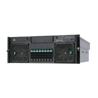
® The Intel Server System S7000FC4UR is a 4U, high-density, rack-mount server system with support for one to four processors and up to 256GB FBDIMM memory. Figure 18 and Figure 19 show the front and rear views of the system. -
Page 91: Figure 19. Intel ® Server System S7000Fc4Ur (Rear View With Top Cover Removed)
® Figure 19. Intel Server System S7000FC4UR (rear view with top cover removed) The power supply modules are located at the rear of system under the main board. The modules plug directly into connectors on the power distribution board. The system supports up to two hot-swap power supply modules in a 1+1 redundant configuration. -
Page 92: External Chassis Features - Front
System Overview Intel® Server System S7000FC4UR External Chassis Features – Front Figure 20 shows the front view of the system with the front bezel removed. The front provides access to the following components: Front panel buttons and LEDs (with optional LCD) -
Page 93: Hard Drive And Peripheral Device Bays
The optical drive and tape backup drive are not hot-swap devices. System power must be turned off when installing or removing these drives. Hard disk drives have different cooling, power, and vibration characteristics; therefore, Intel will ® validate specific hard disk drive types in the Intel Server System S7000FC4UR. -
Page 94: User-Accessible Connectors, Pci Slots And Leds
System Overview Intel® Server System S7000FC4UR Figure 21. Rear View 8.2.1 User-Accessible Connectors, PCI Slots and LEDs Table 18. lists the user-accessible connectors at the rear of the system. Table 18. User-Accessible Connectors, PCI Slots, and LEDs Item Description Serial port connector... -
Page 95: Power Distribution Board (Pdb)
The SATA-to-PATA converter board receives the SATA signal from the main board via a x1 SATA cable and converts it to IDE signals routed to the optical drive. 8.2.6 Intel® Remote Management Module 2 (Intel® RMM2) ® The Intel RMM2 contains the remote server management support. The module plugs into a connector provided on the I/O riser board. -
Page 96: Cooling Subsystem
With one power supply module installed, the system does not have redundant power. At 200-240VAC input, one power supply module is capable of handling the maximum power ® requirements for a fully configured Intel Server System S7000FC4UR, which includes the following: Four processors 256GB of memory... -
Page 97: Specifications
Intel® Server System S7000FC4UR TPS System Overview Specifications 8.5.1 Environmental Specifications The production system will be tested to the environmental specifications as indicated in Table Table 19. Environmental Specifications Summary Environment Specification Temperature operating 10°C to 35°C (50°F to 95°F) Temperature non-operating -40°C to 70°C (-40°F to 158°F) - Page 98 System Overview Intel® Server System S7000FC4UR Weight 90 lbs (40 kg) 1. The system weight listed above is an estimate for a fully configured system and will vary depending on Note: number of peripheral devices and add-in cards, as well as the number of processors and DIMMs installed in the system.
-
Page 99: System Chassis And Sub-Assemblies
Intel® Server System S7000FC4UR TPS System Chassis and Sub-Assemblies System Chassis and Sub-Assemblies This section describes the system chassis and its sub-assemblies. Base Chassis and Top Covers 9.1.1 Base Chassis The system fits into a standard 19-inch EIA rack and is 4U high x 28-inches deep. The 4U height is defined by standard EIA rack units where 1U = 1.75-inches. -
Page 100: Power And Fan Subsystems
System Chassis and Sub-Assemblies Intel® Server System S7000FC4UR Slide Rail Mounting Points (both sides) Figure 22. Slide Rail Mounting Features Power and Fan Subsystems 9.2.1 Power Subsystem The power bay provides space for two power supply modules and the power distribution board (PDB). -
Page 101: Fan Subsystem
Intel® Server System S7000FC4UR TPS System Chassis and Sub-Assemblies Figure 23. Power Supply Module 9.2.2 Fan Subsystem Two fan assemblies are located at the front of the chassis and are removed from the front (See Figure 9). Each assembly contains two fans. The fans are in a sheetmetal enclosure with a plastic bezel mounted to the front. -
Page 102: Figure 25. Front Fan Assembly
System Chassis and Sub-Assemblies Intel® Server System S7000FC4UR Figure 25. Front Fan Assembly Figure 26. Rear Fan Revision 1.0... -
Page 103: Main Board Subsystem
Intel® Server System S7000FC4UR TPS System Chassis and Sub-Assemblies Main Board Subsystem The main board mounts to a sheet metal tray with four metal brackets from the Component Enabling Kit (CEK) and four loose screws. The main board assembly is mounted in the chassis via slot and tab hooks and secured by a single captive plunger. -
Page 104: Hard Drive Carrier
System Chassis and Sub-Assemblies Intel® Server System S7000FC4UR 9.4.1 Hard Drive Carrier The hard drive carrier is an assembly that provides guidance for hot swapping. It contains two integrated light pipes to transfer the LED indicator light from the SAS backplane to the front, and an insertion/extraction mechanism that includes a hard drive bezel. -
Page 105: Front Bezel
Intel® Server System S7000FC4UR TPS System Chassis and Sub-Assemblies Front Bezel The front bezel assembly is a single-piece design that attaches to features on the front of the chassis and covers the hard drives, peripheral device, and front panel buttons/connectors. The front panel LEDs are visible through the bezel. -
Page 106: 10. 1570W Power Supply
1570W Power Supply Intel® Server System S7000FC4UR 10. 1570W Power Supply This section describes some of the power supply features. It is a current sharing power supply with auto ranging input. The dimensions of the power supply are 7.75-inches (W) x 14.5-inches (D) x 1.47-inches (H). -
Page 107: Auto Restart
Intel® Server System S7000FC4UR TPS 1570W Power Supply For any conditions during turn-on, the inrush current will not open the primary input fuse or damage any other components. 10.1.5 Auto Restart Although the power supply may power off under the conditions mentioned in Sections 10.1.3 and 10.1.4, it is capable of restarting, either automatically or under program control after the... -
Page 108: Output Current Rating
1570W Power Supply Intel® Server System S7000FC4UR 10.2.2 Output Current Rating The combined continuous output power for all outputs will not exceed 1570W. Each output has a maximum and minimum current rating shown in Table 23. Table 23. 1570W Load Ratings... -
Page 109: Over-Current Protection
Intel® Server System S7000FC4UR TPS 1570W Power Supply 10.2.4 OverCurrent Protection Over-current is a fault condition defined as a 10A/s current ramp starting from full load applied to the output under test. A fault on any output will cause the rest of the outputs to latch off. (See note 4.) -
Page 110: Current Sharing
1570W Power Supply Intel® Server System S7000FC4UR 10.2.7 Current Sharing Outputs of two (or more) supplies connected in parallel must meet the regulation requirements of a single supply. Under normal operation with two (or more) supplies running in parallel the following outputs must share load current. -
Page 111: Power Supply Module Led Indicators
Intel® Server System S7000FC4UR TPS 1570W Power Supply 10.2.9 Power Supply Module LED indicators 10.2.9.1 Power Supply Fail This amber LED is driven by internal circuitry and will illuminate when a power rail has failed. The LED should not be illuminated if the supply turns off due to PS_KILL. The LED will illuminate even if the power supply is in a latched state. -
Page 112: 11. Power Distribution Board
Power Distribution Board Intel® Server System S7000FC4UR 11. Power Distribution Board The power distribution board provides docking connectors for the hot-swappable power supply modules and distribute power to the main board and SAS backplane. A group of comparators on the PDB supplies total power consumption information to the system main board. The board also contains EEPROM FRU information storage. -
Page 113: Vin_Good
Intel® Server System S7000FC4UR TPS Power Distribution Board In the event AC main power is lost, or a fan has failed, this signal must be driven low at least 1ms before any of the outputs go out of regulation. The output will be an open collector/drain. It will be capable of driving the output below 0.4V with a load of 4mA. -
Page 114: 12. Front Panel I/O And Control Boards
Front Panel I/O and Control Boards Intel® Server System S7000FC4UR 12. Front Panel I/O and Control Boards The front panel I/O board gives the end user access to the system video and USB interfaces. It also interfaces with the front panel control module that contains the buttons and LEDs. -
Page 115: 12.2 Functional Architecture
Intel® Server System S7000FC4UR TPS Front Panel I/O and Control Boards 12.2 Functional Architecture This section provides a more detailed architectural description of the front panel I/O board’s functional blocks. 12.2.1 The front panel I/O board passes the VGA video signals from the main board 100-pin connector to the external video connector. -
Page 116: 12.3 Front Panel Control Module
Front Panel I/O and Control Boards Intel® Server System S7000FC4UR 12.3 Front Panel Control Module The front panel control module provides button inputs and LED indicators for the system. It snap-fits into the system front plate and connects to the front panel I/O board through a 50-pin connector. -
Page 117: Figure 31. Non-Lcd Control Module
Intel® Server System S7000FC4UR TPS Front Panel I/O and Control Boards If the LEDs were activated by a button, they cannot be turned off remotely. If the LEDs were activated remotely, the buttons cannot turn them off. Figure 31. Non-LCD Control Module... -
Page 118: Basic Input/Output System (Bios)
Intel® Server System S7000FC4UR 13. Basic Input/Output System (BIOS) ® This chapter describes the functionality of the Basic Input Output System (BIOS) for the Intel Server System S7000FC4UR. It is written for persons involved in design, validation, integration, ® manufacture, and support. It is assumed that the reader is familiar with Intel processors and the standards that define server architecture. - Page 119 Intel® Server System S7000FC4UR TPS Basic Input/Output System (BIOS) YYYY = Four-digit year HH = Two-digit hour using 24 hour clock MM = Two-digit minute For example, BIOS Build 1, generated on September 18, 2006 at 05:56 AM has the following BIOS ID string that is displayed in the POST diagnostic screen: S7000FC4UR.86B.01.00.0001.091820060556...
-
Page 120: 14. Bios Initialization
BIOS Initialization Intel® Server System S7000FC4UR 14. BIOS Initialization 14.1 Processors 14.1.1 Multiple Processor Initialization IA-32 processors have a microcode-based Boot Strap Processor (BSP) arbitration protocol. The system BSP starts executing from the reset vector (F000:FFF0h). Any processor not performing the role of system BSP is called an application processor (AP). -
Page 121: Microcode Update
14.1.4 Microcode Update IA-32 processors can correct specific errata by loading an Intel-supplied data block, known as a microcode update. The BIOS stores the update in non-volatile memory and loads it into each processor during POST. The BIOS allows microcode updates to be stored in the flash. This is limited by the amount of free space available. -
Page 122: Execute Disable Bit Feature
14.1.8 Execute Disable Bit Feature ® The Execute Disable Bit feature (XD bit) is an enhancement to the Intel IA-32 architecture. An IA-32 processor supporting the Execute Disable Bit feature can prevent data pages from being used by malicious software to execute code. An IA-32 processor with the XD bit feature can provide memory protection in either of the following modes: Legacy protected mode if Physical Address Extension (PAE) enabled. -
Page 123: Intel Core Multi-Processing (Cmp)
Creates a separate ACPI MADT table entry for each logical processor. This causes Windows Device Manager to display a separate processor icon for all logical processors. Creates a separate Multiprocessor Specification, Revision 1.4, May 1997, Intel Corporation table entry for each logical processor SMBIOS Type 4 structure shows only the physical processors installed. -
Page 124: Fake Msi" Support
The guest operating system(s) are not exposed to any error conditions. ® Note: If the Setup options are changed to enable or disable the Intel Virtualization Technology Setting in the processor, the user must be fully powered off and powered back on again before the changes take effect. -
Page 125: Direct Cache Access (Dca)
14.1.15 Direct Cache Access (DCA) ® ® Direct cache access (DCA) is a component of Intel I/O Acceleration Technology (Intel I/OAT) as described in Section 20.1. The DCA mechanism is a system-level protocol in a multi-processor system to improve I/O network performance, thereby resulting in higher system performance. -
Page 126: Snoop Filter
PECI is a new thermal management interface. It uses a wire bus interface to provide a communication channel between an Intel processor and an external monitoring device (PECI host controller). The PECI host controller for this system is the ADT7490*. The processors provide processor temperature via PECI interface. -
Page 127: Processor Configuration Errors
Intel Corporation. ® ® The BIOS does not check for mixed processor steppings. See the Intel Xeon Processor Specification Update for supported mixed processor steppings. -
Page 128: Table 28. Mixed Processor Configurations
BIOS Initialization Intel® Server System S7000FC4UR 14.1.18.4 Mixed Processor Speeds Processors with different speeds can be mixed in a system. If this condition is detected, all processor speeds are set to the lowest common denominator (highest common speed) if possible. See Table 28 for more information. -
Page 129: 14.2 Memory
Intel® Server System S7000FC4UR TPS BIOS Initialization Error BIOS Response Processor microcode Logs the error into the SEL missing Alerts the BMC of the configuration error with the IPMI Set Processor State command indicating a configuration error for all mismatched processors. - Page 130 BIOS Initialization Intel® Server System S7000FC4UR 14.2.1.2 FBDIMM Sockets Each memory riser board supports eight FBDIMM sockets for a total of 32 FBDIMM sockets. The memory riser board FBDIMM sockets are silk screened from DIMM_1 to DIMM_8 sequentially from the top to bottom of the board.
-
Page 131: Memory Population Table
Intel® Server System S7000FC4UR TPS BIOS Initialization Memory Memory Memory Memory Riser Riser Riser Riser DIMM 8 DIMM 8 DIMM 8 DIMM 8 DIMM 7 DIMM 7 DIMM 7 DIMM 7 DIMM 6 DIMM 6 DIMM 6 DIMM 6 DIMM 5... -
Page 132: Table 29. Memory Population
BIOS Initialization Intel® Server System S7000FC4UR Table 29. Memory Population Branch 0 Branch 1 Configuration Board A Board B Board C Board D × DIMM_1 × × × DIMM_1 × × × × DIMM_2 DIMM_1 DIMM_2 × × × ×... - Page 133 Intel® Server System S7000FC4UR TPS BIOS Initialization Branch 0 Branch 1 Configuration Board A Board B Board C Board D DIMM_1 DIMM_1 DIMM_1 DIMM_1 DIMM_2 DIMM_2 DIMM_2 DIMM_2 DIMM_3 DIMM_3 DIMM_3 DIMM_3 DC6_ABCD S, M DIMM_4 DIMM_4 DIMM_4 DIMM_4 DIMM_5...
-
Page 134: Modes Of Operation
BIOS Initialization Intel® Server System S7000FC4UR 14.2.3 Modes of Operation The BIOS configures the system memory into the best possible configuration after comparing the current FBDIMM population with the desired memory configuration selected by the user in BIOS Setup. Possible configurations are: Dual-channel Mode (Maximum Performance Mode): The default setting providing the highest system performance and increased FBD bandwidth. -
Page 135: Figure 34. Memory Population For Single-Channel With Minimal Upgrade
Intel® Server System S7000FC4UR TPS BIOS Initialization memory. The BIOS automatically disables any FBDIMM that fails to conform to the rules during the POST memory initialization. Memory Riser DIMM 8 DIMM 7 DIMM 6 DIMM 5 DIMM 4 DIMM 3... -
Page 136: Figure 35. Memory Population For Single-Channel With Multiple Fbdimms
BIOS Initialization Intel® Server System S7000FC4UR Figure 35. Memory Population for Single-Channel with Multiple FBDIMMs This configuration: Low-performance mode, and is a fail-safe mode when the DIMMs cannot be lock- stepped and the system has multiple DIMMs on Memory Riser Boards A and B. -
Page 137: Figure 36. Memory Population For Single-Channel Failsafe
Intel® Server System S7000FC4UR TPS BIOS Initialization Memory Memory Riser Riser DIMM 8 DIMM 8 DIMM 7 DIMM 7 DIMM 6 DIMM 6 DIMM 5 DIMM 5 DIMM 4 DIMM 4 DIMM 3 DIMM 3 DIMM 2 DIMM 2 Disabled... -
Page 138: Figure 37. Memory Population For Single-Channel Failsafe
BIOS Initialization Intel® Server System S7000FC4UR Memory Memory Memory Riser Riser Riser DIMM 8 DIMM 8 DIMM 8 DIMM 7 DIMM 7 DIMM 7 DIMM 6 DIMM 6 DIMM 6 DIMM 5 DIMM 5 DIMM 5 DIMM 4 DIMM 4... -
Page 139: Figure 38. Memory Population For Dual-Channel Configuration On One Branch
Intel® Server System S7000FC4UR TPS BIOS Initialization Memory Memory Riser Riser DIMM 8 DIMM 8 DIMM 7 DIMM 7 DIMM 6 DIMM 6 DIMM 5 DIMM 5 DIMM 4 DIMM 4 DIMM 3 DIMM 3 DIMM 2 DIMM 2 Loc - ste... -
Page 140: Figure 39. Memory Population For Dual-Channel Configuration On Both Branches
BIOS Initialization Intel® Server System S7000FC4UR Memory Memory Memory Memory Riser Riser Riser Riser DIMM 8 DIMM 8 DIMM 8 DIMM 8 DIMM 7 DIMM 7 DIMM 7 DIMM 7 DIMM 6 DIMM 6 DIMM 6 DIMM 6 DIMM 5... -
Page 141: Dimm Sparing Population Rules
Intel® Server System S7000FC4UR TPS BIOS Initialization Memory Memory Memory Riser Riser Riser DIMM 8 DIMM 8 DIMM 8 DIMM 7 DIMM 7 DIMM 7 DIMM 6 DIMM 6 DIMM 6 DIMM 5 DIMM 5 DIMM 5 DIMM 4 DIMM 4... -
Page 142: Figure 41. Memory Population For Dual-Channel On One Branch With Sparing
BIOS Initialization Intel® Server System S7000FC4UR The BIOS Setup utility provides an option to enable sparing. When sparing is selected, the BIOS attempts to enable the feature on both branches, but the actual configuration for a given branch depends on the population of FBDIMMs on that branch. -
Page 143: Figure 42. Memory Population For Dual-Channel On Both Branches With Sparing
Intel® Server System S7000FC4UR TPS BIOS Initialization Memory Memory Memory Memory Riser Riser Riser Riser DIMM 8 DIMM 8 DIMM 8 DIMM 8 DIMM 7 DIMM 7 DIMM 7 DIMM 7 DIMM 6 DIMM 6 DIMM 6 DIMM 6 DIMM 5... -
Page 144: Mirroring Population Rules
BIOS Initialization Intel® Server System S7000FC4UR 14.2.6 Mirroring Population Rules Memory mirroring relies on the dual-channel mode of operation with both branches enabled. The two branches provide mirror copies of each other for redundancy. Therefore, the system must operate in dual-channel mode with an identical memory configuration between channels on one branch (for dual-channel operation) and an identical memory configuration between branches (for mirror support). -
Page 145: Memory Sizing And Configuration
Memory Sizing and Configuration The BIOS supports various memory module sizes and configurations. These combinations of sizes and configurations are valid only for FBDIMMs approved by Intel. The BIOS reads the Serial Presence Detect (SPD) SEEPROMs on each installed FBDIMM to determine the supported size and timing characteristics. -
Page 146: Memory Reservation For Memory-Mapped Functions
Memory Mapped Configuration Region. ® Operating systems must support Physical Address Extensions (PAE) or Intel EM64T technology to utilize memory mapped above the 4GB boundary and recapture this memory for operating system and application use. Most operating systems support this feature. See the relevant operating system manuals for details. -
Page 147: Post Memory Test
Note: The Interrupt 15h, Function E820h system address map reports the memory hole region as reserved (not available memory). Any physical memory behind the hole is relocated above ® the 4GB boundary and is available to operating systems that support PAE or Intel EM64T. See Section 14.2.9 for more information. -
Page 148: Memory Reliability, Availability, Serviceability (Ras)
BIOS Initialization Intel® Server System S7000FC4UR 14.2.13 Memory Reliability, Availability, Serviceability (RAS) 14.2.13.1 RAS Features The following memory RAS features are supported: Memory scrub engine Memory sparing Memory mirroring Automatic thermal throttling 14.2.13.2 Memory Scrub Engine The chipset MCH incorporates a memory scrub engine. This integrated component, when enabled, performs periodic checks on the memory cells. - Page 149 Intel® Server System S7000FC4UR TPS BIOS Initialization The underlying assumption is that FBDIMMs generating increasing numbers of ECC Correctable Errors are eventually prone to ECC Uncorrectable Errors. These FBDIMMs should be removed from service prior to causing a system crash.
-
Page 150: Memory Sub-System Errors
BIOS Initialization Intel® Server System S7000FC4UR memory configuration. BIOS Setup then displays the selected memory configuration on the next boot. 14.2.14 Memory Sub-System Errors This section describes the BIOS and chipset policies used for handling and reporting errors occurring in the memory sub-system. - Page 151 Intel® Server System S7000FC4UR TPS BIOS Initialization 14.2.14.2 Memory BIST (MemBIST) The BIOS enables the MemBIST hardware engine during POST memory initialization on every boot. The MemBIST hardware engine isolates failed FBDIMMs. The BIOS then completes the following actions: Marks those FBDIMMs as failed...
-
Page 152: Table 30. Leaky Bucket Counter Error Decay Periods
BIOS Initialization Intel® Server System S7000FC4UR FBDIMM. A degrading DRAM typically generates errors faster over time, which is detected by the leaky bucket algorithm. The BIOS initializes the LBC for memory ECC correctable errors to a value of 10. These counters are on a per-rank basis. - Page 153 Intel® Server System S7000FC4UR TPS BIOS Initialization 14.2.14.4.4 Recoverable Error Handling in Redundant / Mirror Mode Memory write cycles are issued to both mirror domains (i.e. MCH branches). Memory read cycles can be issued to either mirror domain / branch.
-
Page 154: Table 31. Memory Error Reporting Agent Summary
BIOS Initialization Intel® Server System S7000FC4UR See the chipset technical documentation for a detailed description regarding the FBDIMM Error Recovery Scheme. The documentation covers both memory read and memory write transactions in redundant mode. 14.2.14.5 Memory Error Handling Memory errors are reported through a variety of platform-specific elements, as described in this section. -
Page 155: Table 32. Memory Error Handling - Post
Intel® Server System S7000FC4UR TPS BIOS Initialization Table 32. Memory Error Handling — POST Error POST System Event Log (SEL) DIMM Fault LED IPMI Memory RAS System Scenario Behavior System Fault LED Behavior Operation ® Intel MemBIST Uncorrectable Error UE POST code... -
Page 156: Table 33. Memory Ecc Error Handling - Runtime, Non-Redundant Configuration
BIOS Initialization Intel® Server System S7000FC4UR Table 33. Memory ECC Error Handling — Runtime, Non-Redundant Configuration Error Scenario System Event Log DIMM Fault LED1 IPMI Memory RAS Behavior System Operation (SEL) System Fault LED Correctable Errors CE SEL message DIMM LED: Set DIMM State The system continues to operate. -
Page 157: Table 34. Memory Ecc Error Handling - Runtime, Redundant Configuration
Intel® Server System S7000FC4UR TPS BIOS Initialization Table 34. Memory ECC Error Handling — Runtime, Redundant Configuration Error System Event Log (SEL) DIMM Fault LED IPMI Memory RAS System Scenario System Fault LED Behavior Operation Config = Sparing CE SEL message... - Page 158 BIOS Initialization Intel® Server System S7000FC4UR Config = Sparing UE SEL message DIMM Fault LED: Set DIMM State: The system asserts an NMI. identifying FBDIMM Post-SFO4 On for the failed pair of DIMM failure status = Y location FBDIMMs in lock-step Set Memory RAS Redun.
- Page 159 Intel® Server System S7000FC4UR TPS BIOS Initialization Config = Mirror UE SEL message DIMM Fault LED: Set DIMM State: The system asserts an NMI when: identifying FBDIMM Current State: On for the failed pair DIMM failure status = Y AMB fast reset fails on both branches.
-
Page 160: Server Management Aspects Of Memory And Memory Ras
Server Management Aspects of Memory and Memory RAS The BIOS is responsible for communicating the current memory and memory RAS configuration to the BMC. There are three separate IPMI Intel OEM commands for this purpose: Set DIMM State Set Memory RAS Configuration... - Page 161 Intel® Server System S7000FC4UR TPS BIOS Initialization Command Request / Response Data Description For Bytes 2–6 a bitmap format is supported where each bit corresponds to one FBDIMM socket on the memory riser board indicated in Byte 1 Group ID field:...
- Page 162 [1] = Memory Branch 1 has DIMMs marked for sparing Mirroring Domain Enable Mask is: [0] = Memory Branches 0 and 1 are mirrored (only possible configuration on the chipset MCH). Revision 1.0 Intel order number E18291-001...
-
Page 163: 14.3 I/O Subsystem
Universal Serial Bus v1.1 Specification and Universal Serial Bus Revision 2.0 Specification Serial ATA Revision 2.5 Specification, Serial ATA International Organization (SATA-IO) Intel Low Pin Count Interface Specification, Revision 1.1. Intel Corporation. 14.3.1.1 API Specification Compliance BIOS Boot Specification Version 1.01. Compaq Computer Corporation, Phoenix Technologies Ltd., Intel Corporation. - Page 164 Legacy Shadow RAM region resources in the C000h and D000h segments. In most cases, Legacy Option ROM execution is not required unless its device is an Initial Program Load (IPL) device for a legacy operating system. Revision 1.0 Intel order number E18291-001...
-
Page 165: Pci Express* Hot-Plug
82575EB support) Intel iSCSI (Combined Option ROM for Intel 82563EB and Intel 82575EB support) Note: The LSI* SAS IR and Software RAID mode Option ROM images are integrated directly on the SAS riser board instead of the System BIOS image. - Page 166 The PCI Express Base Specification, Revision 1.1 defines a standard usage model for PCI Hot- plug. The usage model specifies several elements including the state of the indicator LEDs’ interlocking switches. The server provides these hardware elements and the BIOS supports them in accordance with this specification. Revision 1.0 Intel order number E18291-001...
-
Page 167: Table 38. Pci Hot-Plug Power Indication
Intel® Server System S7000FC4UR TPS BIOS Initialization 14.3.4.3 Operating System Interfaces 14.3.4.3.1 ACPI Control Methods PCI hot-plug requires an ACPI hot-plug aware operating system. The ACPI methods provided in the BIOS support the standard hot-plug controller usage model. 14.3.4.3.2 PCI Hot-plug Usage Model This section describes the hot-plug usage model for PCI Express* slots. -
Page 168: Pnp Isa
BIOS is capable of initializing and using the following types of USB devices: USB Specification compliant keyboards USB Specification compliant mice USB Specification compliant storage devices utilizing the bulk-only transport mechanism USB devices are scanned to determine if they are required for booting. Revision 1.0 Intel order number E18291-001... -
Page 169: Serial Ata (Sata) Support
Intel® Server System S7000FC4UR TPS BIOS Initialization The BIOS supports Universal Serial Bus Revision 2.0 Specification mode of operation, and as such supports Universal Serial Bus Revision 1.1 Specification and Universal Serial Bus Revision 2.0 Specification compliant devices and host controllers. -
Page 170: 14.4 Fan Speed Control And Thermal Management
ESB2 BMC Core TPS Runtime support routines The exact layout is subject to change as determined by Intel. A 64 KB block is available for storing OEM custom logos. The flash ROM contains the necessary drivers for onboard peripherals including the following:... -
Page 171: Table 40. Thermal Profile Data Sdr Record Format
FBDIMMs. Table 40. Thermal Profile Data SDR Record Format Byte Name Description OEM ID Intel manufacturers ID – 157h, little endian Record Subtype Value 0Bh Throttling Mode Indicates throttling mode. 01: Open Loop 02: Closed Loop. Profile Support Bitmap... -
Page 172: Processor Thermal Management
If for any reason the system cannot be successfully configured for Static CLTT operation, the BIOS programs the system for Static Open Loop Thermal Throttling (OLTT) operation instead. This is in conformance with the requirements described in the Intel ®... -
Page 173: 15. Bios User Interface
ROM in BMP format. Resolution up to 800 x 600 in any color depth is supported. A standard Intel Splash Logo is included in the flash ROM. An OEM can load a customized splash logo. See section 16.2.1. -
Page 174: 15.2 Bios Setup Utility
The BIOS displays a “Press <F2> to enter setup” message during POST. The message is displayed on the POST diagnostic screen if Quiet Boot is disabled or under the Splash Screen if Quiet Boot is enabled. Revision 1.0 Intel order number E18291-001... -
Page 175: Table 42. Bios Setup - Keyboard Command Bar
Intel® Server System S7000FC4UR TPS BIOS User Interface 15.2.2.2 Keyboard Commands The bottom right portion of the Setup screen provides a list of commands that are used to navigate through the Setup utility. These commands are displayed at all times. -
Page 176: Bios Setup Utility Screens
Information in the Options column enclosed in brackets (< >) using light grey text indicates Information Only fields that the user cannot modify. Information in square brackets ([ ]) indicates fields in which the user needs to type in text instead of selecting from a provided option. Revision 1.0 Intel order number E18291-001... -
Page 177: Figure 44. Setup Utility - Main Screen Display
Intel® Server System S7000FC4UR TPS BIOS User Interface The system requires a save and reboot whenever information is changed (except the System Date and System Time fields). Pressing <ESC> discards the changes and continues booting the system according to the boot order set from the last boot. -
Page 178: Table 43. Setup Utility - Main Screen Fields
Enabled screen during POST. no other data is viewable in Disabled POST, this means Option [Disabled] – Display the ROMS are also run under the diagnostic screen during logo and cannot be POST. accessed. Revision 1.0 Intel order number E18291-001... -
Page 179: Figure 45. Setup Utility - Advanced Screen Display
Intel® Server System S7000FC4UR TPS BIOS User Interface Setup Item Options Help Text Comments POST Error Pause Enabled [Enabled] – System will enter Determines whether the the Error Manager for critical BIOS enters the POST Error Disabled POST errors. Manager to display Major errors [Disabled] –... -
Page 180: Figure 46. Setup Utility - Processor Configuration Screen Display
Setup Item Options Help Text Comments Core Frequency <Current Information only Processor Frequency at which processors Frequency> currently run System Bus <Current FSB Information only Frequency Frequency> Current frequency of the processor front side bus Revision 1.0 Intel order number E18291-001... - Page 181 Intel® Server System S7000FC4UR TPS BIOS User Interface Setup Item Options Help Text Comments ® Enhanced Intel Enhanced Intel SpeedStep Enabled ® SpeedStep Tech Technology allows the system to Disabled dynamically adjust processor voltage and core frequency, which can result in decreased...
-
Page 182: Figure 47. Setup Utility - Specific Processor Information Screen Display
Size of the processor L2 cache Processor Stepping <Processor Stepping> Information only Stepping number of the processor CPUID Register <Processor CPUID Information only Value> CPUID register value identifies details about the processor family, model, and stepping. Revision 1.0 Intel order number E18291-001... -
Page 183: Figure 48. Setup Utility - Memory Configuration Screen Display
Intel® Server System S7000FC4UR TPS BIOS User Interface 15.2.3.3 Memory Configuration Screen The Memory Configuration screen provides the ability for a user to view details about system memory configuration. The user can also select options to open the Configure and View Memory RAS screen or the memory riser board Information screens. - Page 184 Memory Riser Board View Memory Riser Select to view information about the specific <n> Information Board and associated memory riser board. Takes the user to a sub- FB-DIMM information. menu screen. Revision 1.0 Intel order number E18291-001...
-
Page 185: Figure 49. Setup Utility - Configure And View Memory Ras Screen Display
Intel® Server System S7000FC4UR TPS BIOS User Interface 15.2.3.3.1.1 Configure Memory RAS and Performance Screen The Configure Memory RAS and Performance screen provides fields to customize several memory configuration options, such as whether to use Memory Mirroring or Memory Sparing. -
Page 186: Figure 50. Setup Utility - Memory Riser Board Information Screen Display
<Current DIMM State> DIMM_4 <Current DIMM State> DIMM_5 <Current DIMM State> DIMM_6 <Current DIMM State> DIMM_7 <Current DIMM State> DIMM_8 <Current DIMM State> Figure 50. Setup Utility — Memory Riser Board Information Screen Display Revision 1.0 Intel order number E18291-001... -
Page 187: Figure 51. Setup Utility - Mass Storage Controller Configuration Screen Display
Intel® Server System S7000FC4UR TPS BIOS User Interface Table 48. Setup Utility — Memory Riser Board Information Screen Fields Setup Item Options Help Text Comments DIMM_# <Current Information only DIMM State> Displays the state of each DIMM socket present on the board. -
Page 188: Table 49. Setup Utility - Mass Storage Controller Configuration Screen Fields
Option ROM enumerates and configures SATA devices as a Redundant Array of Independent Disks (RAID). BIOS Setup does not report device information for any drives configured by the Option ROM as part of a RAID volume. Revision 1.0 Intel order number E18291-001... - Page 189 Intel® Server System S7000FC4UR TPS BIOS User Interface Setup Item Options Help Text Comments SATA Port 0 < Not Installed / Information only Drive Information > This field displays information for the device connected to SATA Port 0. This field is not displayed if the device has been configured as part of a RAID volume.
-
Page 190: Figure 52. Setup Utility - Serial Port Configuration Screen Display
Serial B is no longer available as a serial port Enabled when SOL or EMP mode are in effect. Disabled Address 3F8h Select serial port B base I/O address. 2F8h 3E8h 2E8h Select serial port B interrupt request (IRQ) line. Revision 1.0 Intel order number E18291-001... -
Page 191: Figure 53. Setup Utility - Usb Controller Configuration Screen Display
Intel® Server System S7000FC4UR TPS BIOS User Interface Note: Serial ports cannot be assigned identical I/O Addresses or IRQ assignments. BIOS Setup does not allow the user to exit this screen if both Serial Ports assigned the same I/O Address or IRQ values. -
Page 192: Table 51. Setup Utility - Usb Controller Configuration Screen Fields
10 seconds USB mass storage Timeout device start unit 20 seconds command timeout. 30 seconds Setting to a larger value 40 seconds provides more time for a mass storage device to be ready, if needed. Revision 1.0 Intel order number E18291-001... - Page 193 Intel® Server System S7000FC4UR TPS BIOS User Interface <Mass Storage Auto [Auto] – USB devices A separate line is displayed for each USB mass Device Information> less than 530 MB will be storage emulation device detected. Floppy emulated as floppy.
-
Page 194: Figure 54. Setup Utility - Pci Configuration Screen Display
Enabled / Disabled Slot 4 ROM Enabled / Disabled Slot 5 ROM Enabled / Disabled Slot 6 ROM Enabled / Disabled Slot 7 ROM Enabled / Disabled Figure 54. Setup Utility — PCI Configuration Screen Display Revision 1.0 Intel order number E18291-001... -
Page 195: Table 52. Setup Utility - Pci Configuration Screen Fields
Intel® Server System S7000FC4UR TPS BIOS User Interface Table 52. Setup Utility — PCI Configuration Screen Fields Setup Item Options Help Text Comments Memory Mapped I/O 1.5GB Select the start of the reserved For all PAE (Physical Address Start Address... -
Page 196: Figure 55. Setup Utility - Lan Configuration Screen Display
Help Text Comments ® ® Intel I/OAT Intel I/O Acceleration Enabled ® Technology (Intel I/OAT) Disabled accelerates TCP/IP processing for onboard NICs, delivers data- movement efficiencies across the entire server platform, and minimizes system overhead. Revision 1.0 Intel order number E18291-001... - Page 197 Intel® Server System S7000FC4UR TPS BIOS User Interface Setup Item Options Help Text Comments Onboard NIC 1 ROM Load the embedded option This corresponds to the main Enabled ® ROM for the onboard board Intel 82563EB Ethernet Disabled network controller.
- Page 198 ESB2 BMC Core TPS Setup Item Options Help Text Comments I/O Riser Board NIC2 Enables or disables the I/O This corresponds to the Intel Enabled Riser Board network I/O riser board Intel 82575EB Disabled controller. Ethernet device. This menu item should be suppressed if the I/O riser board is not installed.
-
Page 199: Table 54. Setup Utility - System Acoustic And Performance Configuration Screen Fields
Intel® Server System S7000FC4UR TPS BIOS User Interface 15.2.3.3.8 System Acoustic and Performance Configuration The System Acoustic and Performance Configuration screen provides configuration options for system thermal characteristics and behavior. From the Main screen select Advanced | System Acoustic and Performance Configuration to access this screen. -
Page 200: Figure 56. Setup Utility - System Acoustic And Performance Configuration Screen Display . 177 Figure 57. Setup Utility - Security Configuration Screen Display
Only alphanumeric user password, too. characters can be used. Maximum length is 7 characters. It is case sensitive. Note: Administrator password must be set in order to use the user account. Revision 1.0 Intel order number E18291-001... - Page 201 Intel® Server System S7000FC4UR TPS BIOS User Interface Setup Item Options Help Text Comments Set User Password [123abcd] User password is used to Available only if the Administrator control entry access to Password is installed BIOS Setup Utility. This option is only to control Only alphanumeric access to BIOS Setup.
-
Page 202: Figure 58. Setup Utility - Server Management Configuration Screen Display
AC power loss. [Reset] – System powers on. Clear System Event Log Enabled Clears the System Event Log. All current entries are lost. Disabled Note: This option will be reset to [Disabled] after a reboot. Revision 1.0 Intel order number E18291-001... - Page 203 Intel® Server System S7000FC4UR TPS BIOS User Interface Setup Item Options Help Text Comments Reset on Fatal Error Enabled [Enabled] – System will trigger a The system normally generates reset on fatal errors. a NMI in response to fatal errors Disabled at runtime.
-
Page 204: Figure 59. Setup Utility - Console Redirection Screen Display
[None] – Configure for no flow control. [RTS/CTS] – Configure for hardware flow control. Baud Rate 9.6K Serial port transmission speed: Setting must match the remote 19.2K terminal application. 38.4K 57.6K 115.2K Revision 1.0 Intel order number E18291-001... -
Page 205: Figure 60. Setup Utility - Server Management System Information Screen Display
Intel® Server System S7000FC4UR TPS BIOS User Interface Setup Item Options Help Text Comments Terminal Type PC-ANSI Character formatting used for console redirection. Setting must VT100 match the remote terminal VT100+ application. VT-UTF8 Legacy OS Redirection This option will enable legacy OS Disabled redirection (i.e. -
Page 206: Figure 61. Setup Utility - Intel ® Remote Management Module Information Screen Display
® ® The Intel Remote Management Module Information screen provides options to review information regarding firmware revisions and Intel GCM network devices. ® From the Main screen select Server Management | Intel Remote Management Module Information to access this screen. -
Page 207: Figure 62. Setup Utility - Boot Options Screen Display
Intel® Server System S7000FC4UR TPS BIOS User Interface 15.2.3.8 Boot Options Screen The Boot Options screen displays any bootable media encountered during POST and allows the user to configure their desired boot device. From the Main screen, select Boot Options to access this screen. - Page 208 OS using a bootable option ROM. BEV devices are typically found on remote program load devices. Boot Option Retry Enabled This will continually retry NON-EFI based boot options Disabled without waiting for user input. Revision 1.0 Intel order number E18291-001...
-
Page 209: Figure 63. Setup Utility - Hard Disk Order Screen Display
Intel® Server System S7000FC4UR TPS BIOS User Interface 15.2.3.8.1 Hard Disk Order Screen The Hard Disk Order screen provides a way to control the hard disk boot order. From the Main screen select Boot Options | Hard Disk Order to access this screen. -
Page 210: Figure 65. Setup Utility - Floppy Order Screen Display
From the Main screen select Boot Options | Network Device Order to access this screen. Boot Options Network <Available Network devices> / Disabled Device #<n> Figure 66. Setup Utility — Network Device Order Screen Display Revision 1.0 Intel order number E18291-001... -
Page 211: Figure 67. Setup Utility - Bev Device Order Screen Display
Devices utilizing the BEV method are typically remote program load devices such as network cards. See the BIOS Boot Specification Version 1.01. Compaq Computer Corporation, Phoenix Technologies Ltd., Intel Corporation 1996 for more information. From the Main screen select Boot Options | BEV Device Order to access this screen. -
Page 212: Figure 68. Setup Utility - Boot Manager Screen Display
[EFI Shell] Select this option to boot now. Note: This list is not the system boot option order. Use the Boot Options menu to view and configure the system boot option order. Revision 1.0 Intel order number E18291-001... -
Page 213: Figure 69. Setup Utility - Error Manager Screen Display
Intel® Server System S7000FC4UR TPS BIOS User Interface 15.2.3.10 Error Manager Screen The Error Manager screen displays any errors encountered during POST. Error Manager Exit ERROR CODE SEVERITY INSTANCE < fatal major <1234> minor > <xx> <Error Description> Figure 69. Setup Utility — Error Manager Screen Display Table 67. -
Page 214: Figure 70. Setup Utility - Exit Screen Display
Discard changes made since the last save changes operation was performed. Load Default Values Load factory default values for User is prompted for all BIOS Setup Utility options. confirmation. The [F9] key can also be used. Revision 1.0 Intel order number E18291-001... -
Page 215: 15.3 Loading Bios Defaults
Intel® Server System S7000FC4UR TPS BIOS User Interface Setup Item Options Help Text Comments Save as User Default Save current BIOS Setup User is prompted for Values Utility values as custom user confirmation. default values. If needed, the user default values can be restored via the Load User Default Values option below. -
Page 216: 16. Bios Update Support
1. Configure the Rolling BIOS Jumper to Normal Mode (Pin 2 and 3). 2. Boot the system. ® 3. Update the BIOS using the EFI Flash or Intel One Flash Update (OFU) utility. 4. Reset the system. 5. The Rolling BIOS feature automatically performs the following steps: Boots the system using the old BIOS image. -
Page 217: Rolling Bios Jumper Behavior (Force Other Bank)
The OEM FV may contain an optional OEM Splash Logo for display during POST. The Change Logo utility allows users to replace the standard Intel Splash Logo with a customized OEM Splash Logo. This utility supports BMP files at resolutions up to 800x600 in any color depth. -
Page 218: Oem Strings
The DMIEDIT utility allows users to update several SMBIOS fields including the OEM Strings. See Section 18.5.2 for more information on the DMIEDIT utility. See Section 18.5.3.10 for more information on the SMBIOS Type 11 OEM Strings structure. Revision 1.0 Intel order number E18291-001... -
Page 219: 17. Operating System Boot, Sleep, And Wake
17.1.1 Server Managment Boot Device Control The Intelligent Platform Management Interface Specification, Version 2.0, Intel Corporation specification includes provisions for server management devices to set certain boot parameters by setting boot flags. Among the boot flags (parameter #5 in the IPMI specification), the BIOS checks data 1-3 for forced boot options. -
Page 220: Usb Boot Device Reordering
Security Configuration Screen in the Setup Utility. 17.2 Operating System Support 17.2.1 Microsoft Windows* Compatibility Intel Corporation and Microsoft Corporation co-author design guides for system designers using ® Intel processors and Microsoft* operating systems. The Hardware Design Guide for Microsoft Windows 2000 Server, Version 3.0, Microsoft Corporation is intended for systems designed to... -
Page 221: Table 69. Supported Acpi Tables
Intel® Server System S7000FC4UR TPS Operating System Boot, Sleep, and Wake Provide ACPI table support As described in the ACPI specifications, an ACPI-aware operating system generates an SMI. The SMI requests that the system be switched into ACPI mode. The BIOS responds completing... -
Page 222: 17.3 Front Control Panel Support
The BIOS supports a front control panel non-maskable interrupt (NMI) button. Pressing the NMI button initiates a request that is forwarded directly to the chipset. See Section 17.5 for information on NMI handling. Note: The Front Panel NMI Button is recessed to prevent accidental triggering. Revision 1.0 Intel order number E18291-001... -
Page 223: 17.4 Sleep And Wake Support
Intel® Server System S7000FC4UR TPS Operating System Boot, Sleep, and Wake 17.4 Sleep and Wake Support 17.4.1 System Sleep States The server system supports these ACPI system sleep states: ACPI S0 state – working state ACPI S1 state – low latency sleep state ACPI S4 state –... -
Page 224: Non-Maskable Interrupt (Nmi) Handling
The wake sources for S1 are configured entirely by the operating system using information in ® the ACPI DSDT table. PCI devices (Intel 82563EB NIC) assert PME# signal for WOL when enabled. PME# assertion causes an Out-Of-Band (OOB) wake event. PCI Express* cards also cause wake event for WOL via PME messages or EXP_WAKE signal. -
Page 225: Table 70. Nmi Error Messages
Intel® Server System S7000FC4UR TPS Operating System Boot, Sleep, and Wake The BIOS installs a default NMI handler to respond to NMI events during POST including the EFI Shell environment. This handler detects the NMI source and displays an error message as described in the table below before halting the system. -
Page 226: Ipmi
POST. The events logged by the BIOS comply with the Intelligent Platform Management Interface Specification, Version 2.0, Intel Corporation requirements. IPMI defines the required use of all but two bytes in each event log entry, called Event Data 2 and Event Data 3. -
Page 227: Table 71. Console Redirection Escape Sequences For Headless Operation
Intel® Server System S7000FC4UR TPS BIOS Role in Server Management The BIOS console redirection feature can support both legacy 80x25 text mode as well as EFI graphics console support used to display BIOS Setup and graphics based character display. Redirection of the splash logo image is not supported. -
Page 228: Interface To Server Management
Intel’s server BIOS products. This implementation meets the functional requirements set forth in the Microsoft Windows 2003* WHQL requirements for headless operation of servers. It also maintains a necessary degree of backward compatibility with existing Intel server BIOS products. -
Page 229: Serial Over Lan
Intel® Server System S7000FC4UR TPS BIOS Role in Server Management to a switch. This allows access to each individual server system. The system administrator can remotely switch from one server to another to manage large numbers of servers. BIOS console redirection supports an extra control escape sequence to switch Serial Port B to BMC control. -
Page 230: Wired For Management (Wfm)
ESB2 BMC Core TPS No garbage characters should be seen. Through the redirection capabilities of the BMC on Intel platforms, the Serial Port B (UART) input/output stream can be further redirected and sent over a platform LAN device as a packetized serial byte stream. -
Page 231: Table 72. Smbios Table Entry Point Structure
Intel® Server System S7000FC4UR TPS BIOS Role in Server Management 18.5.1 Access Methods Two access methods are defined for the SMBIOS structures. The first method provides the SMBIOS structures through a PnP function interface. This method is not supported by the BIOS. -
Page 232: Table 73. Smbios Type 0 Structure - Bios Information
Byte String String number of the BIOS Vendors Name. "Intel Corporation". BIOS Version Byte String String number of the BIOS Version. Contains full Intel BIOS ID string. BIOS Starting Address Word Varies Segment BIOS Release Date Byte String String number of the BIOS Release Date. -
Page 233: Table 74. Smbios Type 1 Structure - System Information
Intel® Server System S7000FC4UR TPS BIOS Role in Server Management Offset Name Length Value Description System BIOS Minor Release Byte Varies Minor version of BIOS Identifies the minor release of the System BIOS; for example, the value is 16h for revision 10.22 and 01h for revision 2.1. -
Page 234: Table 75. Smbios Type 4 Structure - Processor Information
Designation the reference designator on the silkscreen of the processor socket ® Processor Byte B3h = Intel Xeon processor family. Type Processor Byte Enum See the System Management BIOS Family Reference Specification, Version 2.5 Revision 1.0 Intel order number E18291-001... - Page 235 Intel® Server System S7000FC4UR TPS BIOS Role in Server Management Offset Name Length Value Description Section 3.3.5.2 for values. Processor Byte String Number of null terminated string. String Manufacturer contains “Intel Corporation”. Processor ID QWord Varies Contains the results of the CPUID...
-
Page 236: Table 76. Smbios Type 7 Structure - Cache Information
01b = Write back 10b = Varies with memory address 11b = Unknown Bit 7 0b = Disabled at boot time 1b = Enabled at boot time Bits 6:5 00b = Internal Bit 4 Revision 1.0 Intel order number E18291-001... - Page 237 Intel® Server System S7000FC4UR TPS BIOS Role in Server Management Offset Name Length Value Description 0 = Reserved Bit 3 1 = Socketed Bits 2:0 Cache level, zero-based Maximum Word Varies Bit 15 Cache Size 0 = 1K granularity 1 = 64K granularity...
-
Page 238: Table 77. Smbios Type 11 Structure - Oem Strings
Only 1 language (English) is supported. Languages Flags Byte Bit Field Bits 7:1 – Reserved Bit 0 – 0 = ISO 639 / ISO 3166 Reserved 15 bytes 015h Current Byte String String number of current language Language (1-based). Revision 1.0 Intel order number E18291-001... -
Page 239: Table 79. Smbios Type 16 Structure - Physical Memory Array
Intel® Server System S7000FC4UR TPS BIOS Role in Server Management 18.5.3.13 Type 16 Structure — Physical Memory Array This structure describes a collection of memory devices that operate together to form a memory address space. The BIOS reports one Type 16 structure for each memory riser board (memory channel) with one or more physical FBDIMMs installed. -
Page 240: Security Features
The SMBIOS Type 24 structure describes the current states of the password and front panel security features. 18.5.3.16 Type 32 Structure — System Boot Information The SMBIOS Type 32 structure is utilized by the client's Pre-eXecution Environment (PXE) to identify the reason why the PXE was initiated. Revision 1.0 Intel order number E18291-001... -
Page 241: Table 81. Smbios Type 38 Structure - Ipmi Device Information
Intel® Server System S7000FC4UR TPS BIOS Role in Server Management 18.5.3.17 Type 38 Structure — IPMI Device Information The SMBIOS Type 38 structure describes the attributes of the embedded IPMI controller on the server board. In addition to the System Management BIOS Reference Specification, Version 2.5... -
Page 242: Security
An Administrator password must be entered in order to set the user password. If only one password is set, this password is required to enter BIOS Setup. Revision 1.0 Intel order number E18291-001... -
Page 243: Table 82. Timestamp Clock Sync Format
Intel® Server System S7000FC4UR TPS BIOS Role in Server Management Entering the user password allows the user to modify only the following: BIOS Setup time Date Boot manager User password menu items Other Setup fields can be modified only if the administrator password is entered. - Page 244 0b = Event is first of the pair 1b = Event is second of the pair [6:4] Reserved [3:0] Timestamp clock sync 0b = SEL Timestamp clock updated 1b = SDR Timestamp clock updated No data Revision 1.0 Intel order number E18291-001...
-
Page 245: Fault Resilient Booting
Error Messages and Beep Codes 19.1 Fault Resilient Booting Fault Resilient Booting (FRB) is an Intel-specific feature that detects and handles errors during the system boot process. The FRB feature provides a recovery mechanism in the event of a system hang during BIOS POST. -
Page 246: Operating System Watchdog Failure
FBDIMM in the system event log. System events handled by the BIOS generate an SMI. After the BIOS finishes logging the error it asserts the NMI if needed. Revision 1.0 Intel order number E18291-001... -
Page 247: Error Sources And Types
Intel® Server System S7000FC4UR TPS BIOS Error Handling The BIOS normally generates a NMI event in response to fatal and uncorrectable errors to prevent continued system operation with corrupted data. Most operating systems halt the system in response to NMI. However, certain Linux releases do not halt the system in response to an NMI event and therefore do not provide effective containment of data corruption. - Page 248 The server system does not support 32-bit PCI slots. The only traditional, 32-bit PCI device is ® the ATI embedded video* on a dedicated 32-bit legacy PCI bus controlled that the Intel ESB2 controls. Video parity errors are not generally considered critical so the server system wires the PERR# signal on this bus to a pull-up connector providing a no connect functionality.
- Page 249 The BIOS does not report PCI Express* errors flagged in either the baseline capability structure or the optional Advanced Error Reporting (AER) structure directly as the Intelligent Platform Management Interface Specification, Version 2.0, Intel Corporation provides no support for reporting PCI Express* errors. Any PCI Express uncorrectable, fatal or uncorrectable, non-fatal errors are propagated to SERR so they are captured by our legacy error handler.
-
Page 250: Table 83. Sel Entry Format - Generic Fields
IPMB slave address. Byte 8 = 0x33: Bit[0] Bit[7:4] System Software ID (SSID) 0b = IPMB slave address 0011b = BIOS SMI Error Handler 1b = System Software ID Byte 9 Bit[3:1] Custom sub-field Revision 1.0 Intel order number E18291-001... - Page 251 Intel® Server System S7000FC4UR TPS BIOS Error Handling Byte Field IPMI Description BIOS Implementation Bit[7:4] = Channel number 001b = Event Data format revision Bit[3:2] = reserved (00b) Bit[0] Bit[1:0] = IPMB device LUN or 1b = System Software ID...
-
Page 252: Table 84. Sel Entry Format - Memory Sensor Type
OEM value or unspecified Memory module/device identification Bit[7:6] = Index into SMBIOS Type 16 entry. This shall be the zero-based memory riser board number. Bit[5:0] = Index into SMBIOS Type17 entry for the failed FBDIMM. Revision 1.0 Intel order number E18291-001... -
Page 253: Table 85. Sel Entry Format - Memory Sensor Type Examples
Firmware Progress sensor type. BIOS only supports the following sensor offset for this sensor type: Sensor Offset 00h — System Firmware Error (POST Error) See the Intelligent Platform Management Interface Specification, Version 2.0, Intel Corporation Table 42-3 for the following implementation details: Table 86. SEL Entry Format — System Firmware Progress Sensor Type... -
Page 254: Table 87. Sel Entry Format - System Firmware Progress Sensor Type Examples
Bit [7:0] The BIOS sends this to the BMC: (ED2) OEM value or unspecified Memory module/device identification Bit [7:6] - Index into SMBIOS Type 16 entry This shall be the zero-based memory riser board number. Revision 1.0 Intel order number E18291-001... -
Page 255: Table 89. Sel Entry Format - Event Logging Disabled Sensor Type Examples
Sensor Offset 05h — PCI SERR Event Sensor Offset 0Ah — Fatal NMI (port 61h, bit 7) Event See the Intelligent Platform Management Interface Specification, Version 2.0, Intel Corporation Table 42-3 for the following implementation details: Table 90. SEL Entry Format — Critical Interrupt Sensor Type... -
Page 256: Table 91. Sel Entry Format - Critical Interrupt Sensor Type Examples
0x05 0x19 Bit[7:3] = 03 Bit[2:0] = 01 PCI SERR on PCI Bus 0 with device and function unknown 0x85 0x00 0xFF Software NMI generated by SMI handler on fatal error 0x09 0xFF 0xFF Revision 1.0 Intel order number E18291-001... -
Page 257: Table 92. Post Error Beep Codes
Intel® Server System S7000FC4UR TPS BIOS Error Handling 19.3 POST Progress Codes and Errors The system BIOS complies with the EFI Framework POST Progress Code specification by reporting 32-bit status codes at various points during POST that contain class, subclass, and operation information. - Page 258 Disabling the video controller (VGA) 0x72 Enabling the video controller (VGA) Remote Console 0x78 Resetting the console controller 0x79 Disabling the console controller 0x7A Enabling the console controller Keyboard (only USB) 0x90 Resetting the keyboard Revision 1.0 Intel order number E18291-001...
- Page 259 Intel® Server System S7000FC4UR TPS BIOS Error Handling Progress Code Progress Code Definition 0x91 Disabling the keyboard 0x92 Detecting the presence of the keyboard 0x93 Enabling the keyboard 0x94 Clearing keyboard input buffer 0x95 Instructing keyboard controller to run Self Test (PS2 only)
-
Page 260: Post Error Manager Messages And Handling
19.3.3.2 Major The system behavior in response to major error is described below: BIOS logs an error to the POST Error Manager. BIOS logs an error message to the BMC System Event Log (SEL). Revision 1.0 Intel order number E18291-001... -
Page 261: Table 94. Post Error Manager Messages And Handling
Intel® Server System S7000FC4UR TPS BIOS Error Handling The BIOS continues booting in a degraded state by default (i.e. BIOS does not automatically enter the POST Error Manager to display the error message). The user can override this default behavior by configuring the BIOS Setup POST Error Pause option to Enabled. - Page 262 Major 8530 Memory failed Self Test (BIST). Memory Board C, DIMM_1. Major 8531 Memory failed Self Test (BIST). Memory Board C, DIMM_2. Major 8532 Memory failed Self Test (BIST). Memory Board C, DIMM_3. Major Revision 1.0 Intel order number E18291-001...
- Page 263 Intel® Server System S7000FC4UR TPS BIOS Error Handling POST Error Code POST Error Manager Message Error Severity 8533 Memory failed Self Test (BIST). Memory Board C, DIMM_4. Major 8534 Memory failed Self Test (BIST). Memory Board C, DIMM_5. Major 8535 Memory failed Self Test (BIST).
- Page 264 Detection (SPD) fail error. Memory Board C, DIMM_8 Component encountered a Serial Presence Major 8577 Detection (SPD) fail error. Memory Board D, DIMM_1 Component encountered a Serial Presence Major 8578 Detection (SPD) fail error. Revision 1.0 Intel order number E18291-001...
- Page 265 Intel® Server System S7000FC4UR TPS BIOS Error Handling POST Error Code POST Error Manager Message Error Severity Memory Board D, DIMM_2 Component encountered a Serial Presence Major 8579 Detection (SPD) fail error. Memory Board D, DIMM_3 Component encountered a Serial Presence...
- Page 266 Memory Board C, DIMM_1 Uncorrectable ECC error encountered. Major 85B1 Memory Board C, DIMM_2 Uncorrectable ECC error encountered. Major 85B2 Memory Board C, DIMM_3 Uncorrectable ECC error encountered. Major 85B3 Memory Board C, DIMM_4 Uncorrectable ECC error encountered. Major Revision 1.0 Intel order number E18291-001...
- Page 267 Intel® Server System S7000FC4UR TPS BIOS Error Handling POST Error Code POST Error Manager Message Error Severity 85B4 Memory Board C, DIMM_5 Uncorrectable ECC error encountered. Major 85B5 Memory Board C, DIMM_6 Uncorrectable ECC error encountered. Major 85B6 Memory Board C, DIMM_7 Uncorrectable ECC error encountered.
- Page 268 PCI Express component encountered a PERR error. Minor A5A1 PCI Express component encountered a SERR error. Fatal A5A4 PCI Express IBIST error. Major DXE boot services driver Not enough memory available to shadow a Minor A6A0 legacy option ROM. Revision 1.0 Intel order number E18291-001...
-
Page 269: New Technologies
A TPM device provides secured storage to store data, such as security keys and passwords. In addition, a TPM device has encryption and hash functions. The Intel Server System S7000FC4UR implements TPM as per TPM PC Client specifications revision 1.2 by the Trusted Computing Group (TCG). -
Page 270: Physical Presence
TPM. This option is used to clear security settings for a newly initialized system or to clear a system for which the TPM ownership security key has been lost. Revision 1.0 Intel order number E18291-001... -
Page 271: Internet Scsi (Iscsi)
82563EB Ethernet device because iSCSI or PXE configures access to all the available ports of the same network. The user must therefore ensure the Intel 82563EB PXE Option ROM is disabled prior to enabling the Intel 82563EB iSCSI Option ROM. -
Page 272: Baseboard Management Controller (Bmc)
This section describes functional and communication interfaces for the enterprise south bridge ® (ESB2) baseboard management controller (BMC) for the Intel Server System S7000FC4UR. It describes the functional blocks of the BMC and the interactions among them. It describes the... -
Page 273: Esb2 Baseboard Management Controller Functionality
Intel® Server System S7000FC4UR TPS Baseboard Management Controller (BMC) 21.1.1 ESB2 Baseboard Management Controller Functionality The BMC is provided by an embedded ARC* controller and associated peripheral functionality that is required for IPMI-based server management. The following is a summary of the ESB2 management hardware features utilized by the BMC: ARC4 processor with 16 Kbytes instruction cache (I-cache) and data cache (D-cache). -
Page 274: Bmc Functional Specifications
AC loss. The BMC responds to the power loss interrupt within 1-2 ms if it is in operational mode. The BMC does not respond to a power-good dropout if it is in firmware transfer mode. Revision 1.0 Intel order number E18291-001... -
Page 275: Power-Up Sequence
Intel® Server System S7000FC4UR TPS BMC Functional Specifications 22.1.3 Power-up Sequence To power up the server, the BMC simulates the front panel power button being pressed for 8 seconds or until POWER_GOOD is asserted. If POWER_GOOD is not asserted within 8 seconds, then a fault is generated. -
Page 276: Power State Retention
The BMC blocks power-on until it is ready for the power-on to occur. See section 22.1.5.3. The BMC must detect when the system is trying to power on and assert the POWER_ON_ENABLE signal for a WOL-initiated DC power-on to occur. Revision 1.0 Intel order number E18291-001... -
Page 277: Table 95. Acpi Power States
Intel® Server System S7000FC4UR TPS BMC Functional Specifications 22.2 Advanced Configuration and Power Interface (ACPI) The BMC works with the ACPI BIOS and with the server board hardware. Table 95. ACPI Power States State Supported Description Working The front panel power LED is on (not controlled by the BMC). -
Page 278: Table 96. System Reset Sources And Actions
If secure mode is enabled or if the reset button is locked by the BMC, then the button does not reset the system. Instead a platform security violation attempt event message is generated if the reset button is pressed. Revision 1.0 Intel order number E18291-001... -
Page 279: Soft Reset And Hard Reset
Intel® Server System S7000FC4UR TPS BMC Functional Specifications 22.3.4 Soft Reset and Hard Reset The BMC monitors an ICH6 signal called BIOS_POST_CMPLT_N, which deasserts at the beginning of POST and asserts at the end of POST. The signal deassertion indicates that a system reset has occurred. -
Page 280: Fault Resilient Booting (Frb)
The BMC cannot indicate which processor is the BSP. Software that needs to identify the BSP should use the multiprocessor specification tables. 22.6 Integrated Front Panel User Interface The front panel has the following indicators: Power LED Revision 1.0 Intel order number E18291-001... -
Page 281: Table 97. Power Led Indicator States
Intel® Server System S7000FC4UR TPS BMC Functional Specifications System status / fault LED Chassis ID LED The front panel provides the following buttons: Reset button Power button System diagnostic interrupt button (NMI button) Chassis ID button 22.6.1 Power LED The green power LED is active when system DC power is on. The power LED reflects a combination of the state of system (DC) power and the system ACPI state. - Page 282 No CPU present or CPU Configuration Errors CPU THERMTRIP No power good – power fault Power unit redundancy sensor – Insufficient resources offset. indicates not enough power supplies present. Not ready AC power off Revision 1.0 Intel order number E18291-001...
-
Page 283: Table 99. Chassis Id Led Indicator States
Intel® Server System S7000FC4UR TPS BMC Functional Specifications Note 1: Support for upper non-critical is not provided in default SDR configuration. If a user enables this threshold in the SDR, then the system status LED behaves as described. 22.6.3 Chassis ID LED The chassis ID LED provides a visual indication of a system being serviced. -
Page 284: Secure Mode And Front Panel Lock-Out Operation
The front panel power and reset buttons must be protected as a unit. They cannot be individually locked. The set of buttons that is protected when secure mode is active varies, depending on the system ACPI power state. Revision 1.0 Intel order number E18291-001... -
Page 285: Table 100. Secure Mode Vs. Acpi State
Intel® Server System S7000FC4UR TPS BMC Functional Specifications Table 100. Secure Mode vs. ACPI State ACPI Power Button Reset Button Diagnostic Interrupt (Front Panel NMI) State Button Button Protected Protected Unprotected Unprotected Unprotected Unprotected Unprotected Unprotected Unprotected Unprotected Unprotected Unprotected 22.6.6... -
Page 286: System Event Log (Sel)
The BMC implements the sensor data record (SDR) repository as specified in the Intelligent Platform Management Interface Specification, Version 2.0. The SDR is accessible through the BMC’s in-band and out-of-band interfaces regardless of the system power state The BMC Revision 1.0 Intel order number E18291-001... -
Page 287: Table 101. Bmc Beep Codes
FRU inventory areas. Note: Fields in the internal use area are not for OEM use. Intel reserves the right to relocate and redefine these fields without prior notification. Definition of this area is part of the software design. -
Page 288: Table 102. Nmi Signal Generation And Event Logging
Chassis Control command (pulse diagnostic – interrupt) Front panel diagnostic interrupt button pressed PEF matching event with diagnostic interrupt – action selected Watchdog Timer pre-timeout expiration with NMI – / diagnostic interrupt action Set NMI Source command – Revision 1.0 Intel order number E18291-001... -
Page 289: Table 103. Processor Sensors
Intel® Server System S7000FC4UR TPS BMC Functional Specifications 22.14 General Sensor Behavior 22.14.1 Sensor Initialization As part of the BMC initialization upon application of standby power or BMC reset, the BMC enables a subset of its sensors. This is done before loading any SDRs. This allows some amount of sensor functionality even if there are no SDRs present. -
Page 290: Processor Vrd Over-Temperature Sensor
22.15.3 Digital Thermal Sensor The Quad-Core Intel® Xeon® Processors 7300 Series or Dual-Core Intel Xeon Processors 7200 Series supports a digital thermal sensor that provides a relative temperature reading that is defined as the number of degrees below the processor’s thermal throttling trip point, also called the PROCHOT threshold. -
Page 291: Processor Thermal Control Monitoring (Prochot)
PECI Interface The platform environment control interface (PECI) is a one-wire, self-clocked bus interface that provides a communication channel between Intel processors and chipset components to an external monitoring device. The PECI bus communicates environment information, such as the temperature data, between the managed components, referred to as the PECI client devices, and the management controller, referred to as the PECI system host. -
Page 292: Standard Fan Management
When a fan is not present, the associated fan speed sensor is put into the reading/state unavailable state, and any associated fan domains are put into the boost state. The fans may already be boosted due to a previous fan failure or fan removal. Revision 1.0 Intel order number E18291-001... -
Page 293: Sleep State Fan Control
Intel® Server System S7000FC4UR TPS BMC Functional Specifications When a removed fan is inserted, the associated fan speed sensor is rearmed. If there are no other critical conditions causing a fan boost condition, the fan speed returns to the nominal state. -
Page 294: Interactions With Dimm Thermal Management
The BMC implements one advanced memory buffer (AMB) aggregate margin temperature sensor for each rear fan domain. 22.17.2 ASHRAE Compliance System requirements for ASHRAE compliance is defined in the S7000FC4UR Fan Speed Control & Thermal Management Platform Architecture Specification. Altitude-related considerations are handled through the chipset throttling configuration. 22.17.3 Platform Configuration 22.17.3.1... -
Page 295: Power Supply Management Interface (Psmi)
Intel® Server System S7000FC4UR TPS BMC Functional Specifications If all fans are present, the BMC installs all fan monitoring SDRs, the full configuration fan redundancy sensor and map SDRs, and the fan control SDRs associated with the full fan configuration. These are designated by the “FAN_FULL” tag in the SDR file. -
Page 296: Power Supply Status Sensors
22.19.4 Power Fault Analysis A single power good signal from each power unit components are monitored by the BMC. The BMC supports individual discrete sensors for the VR/D2D status, for the power fault analysis Revision 1.0 Intel order number E18291-001... -
Page 297: Power Safe
Intel® Server System S7000FC4UR TPS BMC Functional Specifications feature. The BMC monitors the power good signal of each power unit component via the Server Management Diagnostics bus. The BMC generates a SEL event and system beep codes, as shown in Table 101, if the VR/D2D fails due to power good de-assertion. The BMC also provides the failure indications to the front panel system status LED to indicate a critical fault. -
Page 298: System Memory Ras And Bus Error Monitoring
Processor status sensors are manual rearm sensors, so if either of these offsets is asserted, the LED remains lit until the sensor is rearmed. These sensors are not rearmed at system DC power-on or system reset. Revision 1.0 Intel order number E18291-001... -
Page 299: Hot-Swap Controller
Intel RMM2 NIC must both be installed to obtain the features provided by the Intel RMM2. The Intel RMM2 and Intel RMM2 NIC are not hot pluggable, the server’s AC power must be off when an Intel RMM2 and Intel RMM2 NIC are installed. -
Page 300: Memory Region Temperature Monitoring
AMB sensors described above. The BMC disables a memory riser board’s temperature sensors whenever that riser board is not physically present when the BMC’s SDR initialization agent executes. Revision 1.0 Intel order number E18291-001... -
Page 301: Lan Leash Event Monitoring
Intel® Server System S7000FC4UR TPS BMC Functional Specifications 22.26 LAN Leash Event Monitoring The Physical Security sensor is used for monitoring LAN link status and chassis intrusion status. This is implemented as a “LAN Leash” offset in this discrete sensor. This sensor monitors the link state of the two ESB2 embedded LAN channels. -
Page 302: Bmc Messaging Interfaces
BIOS. The BMC implements the optional Get Status / Abort transaction on this interface. Only LUN 1 is supported on this interface. The event message buffer is shared across SMS and SMM interfaces. Revision 1.0 Intel order number E18291-001... -
Page 303: Ipmb Communication Interface
60 ms and a retry count of 3. 23.3 IPMI Serial Feature The IPMI 2.0 Intel implementation of IPMI-over-serial was known before IPMI 1.0 as the emergency management port (EMP) interface. The EMP nomenclature is no longer used. -
Page 304: Invalid Passwords
NIC). There is no server management traffic supported over the IO riser LAN interfaces. One LAN interfaces utilizes an optional external NIC known as the GCM3. Use of this ® NIC requires the presence of the optional Intel Remote Management Module add-in card. -
Page 305: Esb2 Embedded Lan Channels
Intel® Server System S7000FC4UR TPS BMC Messaging Interfaces Session establishment commands are IPMI commands that do not require authentication or an associated session. The BMC supports the following authentication types over the LAN interface. None (no authentication) Straight password / key 23.4.2... -
Page 306: Internet Control Message Protocol (Icmp)
The parameters are implemented on a per-channel basis. Activating SOL This command is not accepted by the BMC, but sent by the BMC is an active session when SOL is activated, to notify a remote client of the switch to SOL. Revision 1.0 Intel order number E18291-001... -
Page 307: Event Filtering And Alerting
Intel® Server System S7000FC4UR TPS Event Filtering and Alerting 24. Event Filtering and Alerting The BMC supports the following IPMI 2.0 alerting features. Platform event filtering (PEF) Dial paging Alert over LAN Alert over serial / point-to-point protocol (PPP). 24.1 Platform Event Filtering (PEF) The BMC monitors platform health and logs failure events into the SEL. -
Page 308: Bmc Flash Update
Flash blocks are erased as necessary before the first write to a block. Revision 1.0 Intel order number E18291-001... -
Page 309: On-Line Firmware Update
Intel® Server System S7000FC4UR TPS BMC Flash Update The boot block area of the flash device is physically protected, either by the design of the flash component or by address-line decoding and write-enable gating. A boot code protection jumper enables updating the boot block. The firmware transfer code cannot sense the state of this jumper, but if the jumper is not in the enabled position, boot block writes fail. -
Page 310: Bios-Bmc Interactions
IPMI 2.0 specification, The BIOS disables PEF when the BIOS Setup Utility is run and restores it restores when the BIOS Setup utility is exited. Watchdog timer interactions: During the boot process, the BIOS uses the BMC’s Watchdog Timer for FRB2. Revision 1.0 Intel order number E18291-001... - Page 311 Intel® Server System S7000FC4UR TPS BIOS-BMC Interactions After the system boots, the BIOS starts the BMC’s Watchdog Timer for “OS Load” usage. To prevent the timer from expiring, server management software agent turns off the timer after the operating system is successfully loaded.
-
Page 312: Sensors
Event Data This is the data that is included in an event message generated by the associated sensor. For threshold-based sensors, the following abbreviations are used: R: Reading value T: Threshold value Revision 1.0 Intel order number E18291-001... - Page 313 Intel® Server System S7000FC4UR TPS Sensors Rearm Sensors The rearm is a request for the event status for a sensor to be rechecked and updated upon a transition between good and bad states. Rearming the sensors can be done manually or automatically. This column indicates the type supported by the sensor.
-
Page 314: Sensors
Redun degrade Degraded from fully redun Redun degrade Degraded from non- redundant Watchdog Watchdog 2 Sensor Timer expired, – Trig Specific status only Offset Hard reset Power down Power cycle Timer interrupt Revision 1.0 Intel order number E18291-001... -
Page 315: Table 104. Sensors
Intel® Server System S7000FC4UR TPS Sensors Sensor Name Sensor # Sensor Type Event / Event Offset Contrib. To Assert / Readable Event Rearm Stand- Reading Type Triggers System Status De-assert Value / Data Offsets Platform Security Platform Sensor Secure mode As and –... - Page 316 Redun degrade Degraded from full Redun degrade Degraded from non- redundant Power Supply Status Power Supply Sensor Presence As and – Trig 4, 1 Specific Offset Failure Degraded A/C lost Degraded Configuration error Revision 1.0 Intel order number E18291-001...
- Page 317 Intel® Server System S7000FC4UR TPS Sensors Sensor Name Sensor # Sensor Type Event / Event Offset Contrib. To Assert / Readable Event Rearm Stand- Reading Type Triggers System Status De-assert Value / Data Offsets Power Supply Status Power Supply Sensor...
- Page 318 Sensor IERR Fatal As and – Trig Specific Offset Thermal trip Fatal Config error Fatal Presence Disabled Degraded Proc 4 Status Processor Sensor IERR Fatal As and – Trig Specific Offset Thermal trip Fatal Revision 1.0 Intel order number E18291-001...
- Page 319 Intel® Server System S7000FC4UR TPS Sensors Sensor Name Sensor # Sensor Type Event / Event Offset Contrib. To Assert / Readable Event Rearm Stand- Reading Type Triggers System Status De-assert Value / Data Offsets Config error Fatal Presence Disabled Degraded...
- Page 320 Connector Specific asserted dependent Offset Device installed Disabled Situation dependent Sparing MEM_C DIMM 1- 8 D0h – Slot Sensor Fault status Situation As and – Trig – Connector Specific asserted dependent Offset Device installed Revision 1.0 Intel order number E18291-001...
- Page 321 Intel® Server System S7000FC4UR TPS Sensors Sensor Name Sensor # Sensor Type Event / Event Offset Contrib. To Assert / Readable Event Rearm Stand- Reading Type Triggers System Status De-assert Value / Data Offsets Disabled Situation dependent Sparing MEM_D DIMM 1- 8 D8h –...
- Page 322 Set Fault Indication command to provide this information to the BMC. See Table 6, System Status LED Indicator States. Note 6: Error logging for this sensor is due to port-mortem memory error scan after an SMI Timeout has occurred. Contribution to system status is determined by the SMI Timeout sensor. Revision 1.0 Intel order number E18291-001...
-
Page 323: Figure 71. Hsc Interface Routing
Intel® Server System S7000FC4UR Hot-Swap Controller (HSC) Architecture 28. Hot-Swap Controller (HSC) Architecture The HSC uses a VSC410* SAF-TE enclosure processor (SEP). This microcontroller employs a v3000 RISC CPU, 8 KB of internal SRAM, GPIO, SGPIO, two general purpose UARTs, one SPI, and four I C compatible interfaces. -
Page 324: Gpio Pins
One for write protection control for both the SPI and I C EEPROM devices Two for SFF-8087 cable detection via side-band ground pins One for jumper selecting either the SR4850HW4M or the S7000FC4UR platform. The default position is the SR4850HW4M platform (no-fill); populate the jumper to select the S7000FC4UR configurations. -
Page 325: Table 106. Platform Identification
Intel® Server System S7000FC4UR HSC Functional Specifications 29. HSC Functional Specifications 29.1 Platform Determination The HSC provides a unique platform identifier through several management interfaces. The table below shows the identifiers returned by the interfaces on the backplane. The I identification is returned as part of the IPMI Get Device ID response. -
Page 326: Table 108. Cable Detect Configuration
HSC Functional Specifications Intel® Server System S7000FC4UR 29.2.2 Sensor Initialization The HSC receives sensor initialization values from the baseboard management controller (BMC). The BMC sends IPMI sensor initialization values to the HSC during IPMI initialization agent runtime. 29.2.3 Cable Detection The HSC detects the presence of the SFF-8087 cables upon firmware initialization. -
Page 327: Hsc Fru Format
FRU data to be written or read via the IPMB. Note: Fields in the internal use area are not for OEM use. Intel reserves the right to relocate and redefine these fields without prior notification. Definition of this area is part of the software design. - Page 328 HSC Functional Specifications Intel® Server System S7000FC4UR 29.7.3 Enclosure Temperature Sensing A temperature sensor device is connected to the HSC via a private I C bus. This device monitors the enclosure temperature. The temperature can be read via SAF-TE, SES2, and IPMI commands.
-
Page 329: Hsc Ipmb Application And Sensors
Intel® Server System S7000FC4UR HSC IPMB Application and Sensors 30. HSC IPMB Application and Sensors This section presents the additional specifications required for the HSC’s implementation as an IPMI controller. See the Intelligent Platform Management Interface Specification for more information. - Page 330 HSC IPMB Application and Sensors Intel® Server System S7000FC4UR Sensor Name Sensor # Sensor Type Event / Reading Event Data Re-arm Event / Threshold (Hex) Type Code Trigger Drive Slot 4 06h 3 Drive Slot Status auto Device Status Rebuilding.
-
Page 331: 30.2.1 Digital And Discrete Sensor Formats
Intel® Server System S7000FC4UR HSC IPMB Application and Sensors 30.2.1 Digital and Discrete Sensor Formats Drive slot sensors have unique, device-specific formats. Table 111. Sensor Formats Sensor Name Sensor # Format (2-bytes) Drive Slot Status 02h-09h Bit 15:13: Reserved. Bit 12: Identify asserted. -
Page 332: Hsc Firmware Update
31.1 HSC Update Over IPMB Firmware updates primarily take place via the IPMB. This method requires a firmware update utility and an Intel hex-format image. The HSC firmware EEPROM is divided into primary and secondary areas. The primary area holds operational code that is in use by the HSC. The secondary area stores an incoming firmware image. -
Page 333: Set Program Segment Command
Intel® Server System S7000FC4UR HSC Firmware Update 31.1.5 Set Program Segment Command This command sets the upper 16 bits of the address for the Firmware Read, Firmware Program, and Get Firmware Range Checksum commands. 31.1.6 FLASH Erase and Sequential Programming There is no explicit erase command. -
Page 334: Glossary
16-bit code. ACPI Advanced Configuration and Power Interface. ACPI is an open industry specification proposed by Intel, Microsoft and Toshiba. ACPI enables and supports reliable power management through improved hardware and operating system coordination. For more information, see ACPI_1.0b or ACPI_2.0. - Page 335 DC-to-DC converter Data Bus deciBel Acoustic ® ® Direct Cache Access. A component of Intel I/O Acceleration Technology (Intel I/OAT) which provides improved I/O network performance. D-cache Data cache. Processor-local cache dedicated for memory locations explicitly loaded and stored by running code.
- Page 336 Glossary Intel® Server System S7000FC4UR Error Correction Code. Refers to a memory system that has extra bit(s) to support limited detection/correction of memory errors. EEPROM Electrically erasable programmable read-only memory Extensible Firmware Interface. A new hardware/operating system interface for the BIOS to utilize in the bootup of the system.
- Page 337 Intelligent Management Bus INIT initialization signal ® ® Intel I/OAT Intel I/O Acceleration Technology ® Intel® Remote Management Module 2 Intel RMM2 ® ® Intel Intel Virtualization Technology I2O-compliant I/O Platforms. These typically contain an I/O processor and I/O subsystem.
- Page 338 Glossary Intel® Server System S7000FC4UR In-Target Probe Japan Aviation Electronics JTAG Joint Test Action Group. It is a test access port used for testing and debugging. An In-Circuit Emulator uses JTAG as a transport mechanism to access an on-chip debug module which is integrated in to the CPU.
- Page 339 PCI Express*. Platform Configuration Register Power distribution board PECI Platform Environmental Control Interface. Platform Event Filtering. ® Pre EFI Initialization. Component of Intel Platform Innovation Framework for EFI architecture. Platform Event Paging Platform Event Trap. Power Factor Correction platform information area 8259 Programmable Interrupt Controller logic.
- Page 340 Glossary Intel® Server System S7000FC4UR Relative Humidity RISC Reduced Instruction Set Computer RMCP+ Remote Management Control Protocol read-only memory ROMB RAID on Motherboard. Revolutions Per Minute ® Runtime. Component of Intel Platform Innovation Framework for EFI architecture. real-time clock Root of Trust Measurement...
- Page 341 Thermal Interface Material. Replaces thermal grease between the HIS and the heatsink. Thermal Monitor. This feature is also known as Automatic Clock Control. Thermal Monitor 2 TCP/IP Offload Engine. A hardware component of Intel Crystal Beach technology. Trusted Platform Management or Module TCG Software Stack Transistor-Transistor Logic...
-
Page 342: Reference Documents
Advanced Configuration and Power Interface Specification, Revision 3.0. Alert Standard Format (ASF) Specification Version 2.0, 23 April 2003, ©2000-2003, Distributed Management Task Force, Inc. http://www.dmtf.org Application Note AP-485: Intel Processor Identification and the CPUID Function, Intel Corporation. http://www.intel.com/design/xeon/applnots/241618.htm BIOS Boot Specification Version 1.01. Compaq Computer Corporation, Phoenix Technologies Ltd., Intel Corporation. - Page 343 IA32 Processor BIOS Writer's Guide, Intel Corporation. Intel Low Pin Count Interface Specification, Revision 1.1. Intel Corporation. http://www.intel.com/design/chipsets/industry/25128901.pdf Intel® Extended Memory 64 Technology BIOS Writer's Guide, IA-32E BIOS Writer’s Guide, Confidential Document (15369), Intel Corporation. Intel® Platform Innovation Framework for EFI Architecture Specification, Intel Corporation.
- Page 344 (PCI-SIG). http://www.pcisig.org/ PCI-Express to PCI/PCI-X Bridge Specification, Revision 1.0. http://www.pcisig.org/ PCI-X Express Specification, Revision 2.0. http://www.pcisig.org/ Platform Environment Control Interface (PECI) Specification, Intel Corporation, Rev 1.1, Ref #21335 Platform Environmental Control Interface Specification, Intel Corporation Platform Management FRU Information Storage Definition v1.0, Intel Corporationh.
- Page 345 Universal Host Controller Interface Design Guide. http://developer.intel.com/design/USB/UHCI11D.htm Universal Serial Bus Revision 1.1 Specification. http://www.usb.org/developers/docs Universal Serial Bus Revision 2.0 Specification. http://www.usb.org/developers/docs Windows Vista BitLocker Client Platform Requirements, Microsoft Corporation. http://www.microsoft.com/whdc/system/platform/hwsecurity/BitLockerReq.mspx Wired For Management Baseline Specification, Revision 2.0. Intel Corporation. Revision 1.0...
Need help?
Do you have a question about the S7000FC4UR and is the answer not in the manual?
Questions and answers