Table of Contents
Advertisement
Quick Links
Advertisement
Table of Contents

Related Manuals for Intel SC450NX - Server Platform - 0 MB RAM


Summary of Contents for Intel SC450NX - Server Platform - 0 MB RAM
- Page 1 SC450NX MP Server System Product Guide Order Number: 700059-002...
- Page 2 Disclaimer Intel Corporation (Intel) makes no warranty of any kind with regard to this material, including, but not limited to, the implied warranties of merchantability and fitness for a particular purpose. Intel assumes no responsibility for any errors that may appear in this document.
-
Page 3: Table Of Contents
Contents Part I: User’s Guide ......................9 1 Chassis Description Chassis Feature Summary ....................12 Chassis Front Controls and Indicators ................13 Chassis Back Controls and Features................14 Chassis Side View ......................15 Peripherals ..........................16 3.5-inch Diskette Drive....................16 3.5-inch Hard Drive Bays....................16 5.25-inch Removable Media Device Bays..............16 Power Supplies ........................17 System Cooling ........................17 Chassis Security........................17... - Page 4 Server Menu .......................42 Boot Menu ........................43 Exit Menu ........................45 Using the System Setup Utility (SSU)..................46 When to Run the SSU ....................46 What You Need to Do....................47 Running the SSU ......................47 Customizing the SSU....................49 Launching a Task .......................49 Resource Configuration Add-in (RCA) Window............50 Multiboot Options Add-in ....................51 Security Add-in ......................52 System Event Log (SEL) Viewer Add-in ..............52...
- Page 5 Part II: Service Technician’s Guide ................85 5 Working Inside the System Tools and Supplies Needed ....................87 Safety: Before You Remove the Access Cover ..............87 Warnings and Cautions .......................88 Access Cover ........................89 Removing the Access Cover..................89 Installing the Access cover ..................90 Subchassis and Electronics Bay..................90 Opening the Subchassis and Electronics Bay.............90 Add-in Boards ........................92...
- Page 6 7 Solving Problems Resetting the System ......................123 Initial System Startup ......................123 Checklist........................123 Running New Application Software ...................124 Checklist........................124 After the System Has Been Running Correctly..............124 Checklist........................124 More Problem-solving Procedures ..................125 Preparing the System for Diagnostic Testing ............125 Using PCDiagnostics ....................125 Monitoring POST ......................126 Verifying Proper Operation of Key System Lights .............126 Confirming Loading of the Operating System ............126...
- Page 7 Hard Drive LED ......................148 ISA ...........................149 PCI ...........................150 Baseboard Jumpers ......................151 General Procedure to Change Jumper Setting ............152 CMOS Clear Jumper ....................152 Password Clear Jumper ...................153 Recovery Boot Jumper .....................153 System I/O Addresses.......................154 Memory Map ........................156 Interrupts...........................157 Video Modes ........................158 A Equipment Log and Configuration Worksheets Equipment Log ......................163 Configuration Worksheets ..................165...
- Page 8 viii...
-
Page 9: Part I: User's Guide
Part I: User’s Guide 1 Chassis Description 2 Baseboard Description 3 Configuration Software and Utilities 4 Exchanging SCSI Hard Drives and Power Supplies... - Page 10 blank page...
-
Page 11: Chassis Description
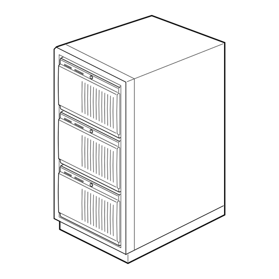
1 Chassis Description The SC450NX MP server is designed to either stand upright (pedestal mode) or be mounted in a rack (rack mode). Figures 1 and 2 show examples of these configurations. Before operation, you must purchase an adapter kit to configure the server for one of the two modes. If you have already created a pedestal server but now want to install it in a rack, you will also need an adapter kit. -
Page 12: Chassis Feature Summary
Chassis Feature Summary The system’s galvanized metal chassis minimizes EMI and radio frequency interference (RFI). The removable access cover is attached to the chassis with two screws. A front subchassis and an electronics bay (at the rear of the main chassis) both rotate outward and can be removed entirely to provide easy access to internal components. -
Page 13: Chassis Front Controls And Indicators
Chassis Front Controls and Indicators OM08001 Figure 3. Front Controls and Indicators External drive bay (5¼”); CD-ROM drive shown installed (not included) Diskette drive C. Power On/Off button (holding down this button for more than four seconds causes a power-button override to the PIIX4E when you release the button) D. -
Page 14: Chassis Back Controls And Features
Chassis Back Controls and Features OM08002 Figure 4. Back Controls and Indicators Parallel port † monitor connector C. Serial port A, COM1 D. Serial port B, COM2 Mouse connector Keyboard connector G. Universal serial bus connector H. Expansion slot covers (six slot connectors provided on baseboard) Power supply bay AC input power connector Power supply fan... -
Page 15: Chassis Side View
Chassis Side View OM08017 Figure 5. Chassis Side View Front swing-out subchassis Diskette drive C. Main chassis D. Power backplane Power supply(s) Baseboard G. Lift-out electronics bay H. 5.25” device bay SCSI hard drive bay Foam cover Foam fan housing Foam fan housing cover... -
Page 16: Peripherals
Peripherals 3.5-inch Diskette Drive The 3.5-inch diskette drive in the 3.5-inch peripheral bay supports 720 KB, and 1.44 MB media. The drive is externally accessible from the front of the system. 3.5-inch Hard Drive Bays The chassis contains one bay for two 3.5-inch-wide (1" high or 1-5/8" high) LVDS SCSI hard drives with internal cabling. -
Page 17: Power Supplies
Power Supplies The chassis can be configured with one, two, or three 400-watt power supplies, each designed to minimize EMI and RFI. Each supply operates within the following voltage ranges and is rated as follows: 100-120 V at 50/60 Hertz (Hz); 7.6 A maximum 200-240 V at 50/60 Hz;... - Page 18 Blank page...
-
Page 19: Baseboard Description
2 Baseboard Description Baseboard Features Table 3. Baseboard Features Feature Description ® Processor Installed: Up to four Pentium II Xeon ™ processors, packaged in single edge contact (S.E.C.) cartridges and installed in 330-pin Slot 2 processor connectors, operating at 1.8 V to 3.5 V. The baseboard's voltage regulator is automatically programmed by the processor's VID pins to provide the required voltage. -
Page 20: Baseboard Connector And Component Locations
Baseboard Connector and Component Locations OM08022 Figure 6. Baseboard Connector and Component Locations Wide SCSI B connector (J9J1) U. VRM connector for processor 1 (J4A1) System jumpers (J6J1) Processor 1 Slot 2 connector (J9A1) C. Hard drive input LED connector (J6J3) W. -
Page 21: Processor
Processor Each Pentium II Xeon processor is packaged in a single edge contact (S.E.C.) cartridge. The cartridge includes the processor core with an integrated 16 KB primary (L1) cache; the secondary (L2) cache; a thermal plate; and a back cover. ™... -
Page 22: Memory
Memory Main memory resides on an add-in board, called a memory module, designed specifically for the SC450NX MP server. The memory module contains slots for 16 DIMMs, each of which must be at least 32 MB, and is attached to the baseboard through a 242-pin connector. Memory amounts from 128 MB to 4 GB of DIMM are supported, with a 64/72-bit four-way-interleaved pathway to main memory, which is also located on the module. - Page 23 System memory begins at address 0 and is continuous (flat addressing) up to the maximum amount of DRAM installed (exception: system memory is noncontiguous in the ranges defined as memory holes using configuration registers). The system supports both base (conventional) and extended memory.
-
Page 24: Peripherals
Peripherals Super I/O Chip The 87309 device supports two serial ports, one parallel port, diskette drive, and PS/2-compatible keyboard and mouse. The system provides the connector interface for each port. Serial Ports Both serial ports are relocatable. By default, port A is physically the top connector, port B on the bottom. -
Page 25: Video
Video The onboard, integrated Cirrus Logic CL-GD5480 64-bit VGA chip contains an SVGA controller † † † † that is fully compatible with these video standards: CGA , EGA , Hercules Graphics, MDA , and VGA. The standard system configuration comes with 2 MB of 10 ns onboard video memory. The video controller supports pixel resolutions of up to 1600 x 1200 and up to 16.7 M colors. -
Page 26: Ide Controller
IDE Controller † IDE is a 16-bit interface for intelligent disk drives with AT disk controller electronics onboard. The PCI/ISA/IDE Accelerator, called PIIX4E, is a multifunction device on the baseboard that acts as a PCI-based Fast IDE controller. The device controls: PIO and IDE DMA/bus master operations Mode 4 timings Transfer rates up to 22 MB/sec... -
Page 27: Server Management
5V_Standby, SEL (and SDRR) information is also available via the interperipheral management bus (IPMB). An emergency management board like the Intel LANDesk SMM board can obtain the SEL and make it remotely accessible using a LAN or telephone line connection. -
Page 28: System Security
System Security To help prevent unauthorized entry or use of the system, the system includes a three-position key lock/switch to permit selected access to drive bays (position is communicated to BMC). The system also includes server management software that monitors the chassis intrusion switch. Mechanical Locks and Monitoring The system includes a chassis intrusion switch. -
Page 29: Summary Of Software Security Features
Summary of Software Security Features Table 5 lists the software security features and describes what protection each offers. In general, to enable or set the features listed here, you must run the SSU and go to the Security Menu (described in this manual on page 41). The table also refers to other SSU menus and to the Setup utility. - Page 30 Table 5. Software Security Features (continued) Feature Description Control access to using To control access to setting or changing the system configuration, set an the SSU: set administrator password and enable it through Setup or the SSU. administrator password If both the administrator and user passwords are enabled, either can be used to boot the system or enable the keyboard and/or mouse, but only the administrator password allows changes to Setup and the SSU.
-
Page 31: Configuration Software And Utilities
3 Configuration Software and Utilities This chapter describes the Power-on Self Test (POST) and system configuration utilities. The table below briefly describes the utilities. Table 6. Configuration Utilities Utility Description and brief procedure Page BIOS Setup If the system does not have a diskette drive, or the drive is disabled or misconfigured, use Setup to enable it. -
Page 32: Power-On Self Test (Post)
Power-on Self Test (POST) Each time you turn on the system, POST starts running. POST checks the baseboard, processors, memory, keyboard, and most installed peripheral devices. During the memory test, POST displays the amount of memory it is able to access and test. The length of time needed to test memory depends on the amount of memory installed. -
Page 33: Using Bios Setup
Using BIOS Setup This section describes the BIOS Setup options. Use Setup to change the system configuration defaults. You can run Setup with or without an OS being present. Setup stores most of the configuration values in battery-backed CMOS; the rest of the values are stored in flash memory. The values take effect when you boot the system. -
Page 34: Setup Menus
In the three conditions listed above, after rebooting, you will see this prompt: Press <F2> to enter SETUP In a fourth condition, when CMOS/NVRAM has been corrupted, you will see other prompts but not the <F2> prompt: Warning: cmos checksum invalid Warning: cmos time and date not set In this condition, the BIOS will load default values for CMOS and attempt to boot. -
Page 35: Main Menu
When you see this: What it means: On screen, an option is shown but you cannot You cannot change or configure the option in that select it or move to that field. menu screen. Either the option is autoconfigured or autodetected, or you must use a different Setup screen, or you must use the SSU. - Page 36 Primary Master and Slave Submenu In the following table, the features other than “Type” appear only for Type Auto if a drive is detected. Table 9. Primary IDE Master and Slave Submenu Feature Choices Description Type Auto Auto allows the system to attempt autodetection of the None drive type.
-
Page 37: Advanced Menu
Keyboard Features Submenu Table 10. Keyboard Features Submenu Feature Choices Description Num Lock Auto Selects poweron state for Num Lock. Key Click Disabled Enables or disables key click. Enabled Keyboard auto-repeat rate 30, 26.7, 21.8, 18.5, 13.3, Selects key repeat rate. 10, 6, or 2 per second Keyboard auto-repeat delay 1/4 sec... -
Page 38: Pci Configuration Submenu
PCI Configuration Submenu The PCI Configuration Menu contains selections that access other submenus. PCI Device, Embedded SCSI Submenu Table 12. PCI Device, Embedded SCSI Submenu Feature Choices Description Option ROM Scan Enabled Enables option ROM scan of the selected device. Disabled Enable Master Disabled... - Page 39 I/O Device Configuration Submenu Table 14. I/O Device Configuration Submenu Feature Choices Description Serial Port A Disabled Enabled Auto Auto forces BIOS to configure the port. OS Controlled OS Controlled displays when OS controls the port. Base I/O Address Selects the base I/O address for COM port A. Interrupt IRQ 4 Selects the IRQ for COM port A.
-
Page 40: Advanced Chipset Control Submenu
Advanced Chipset Control Submenu Table 15. Advanced Chipset Control Submenu Feature Option Description Address Bit Permuting Disabled To be enabled, there must be a power of 2 number of Enabled rows, all rows must be the same size, and all populated rows must be adjacent and start at row 0. -
Page 41: Security Menu
Security Menu You can make the following selections on the Security Menu. Enabling the Supervisor Password field requires a password for entering Setup. The passwords are not case sensitive. Table 16. Security Menu Feature Choices Description Administrator Password is Clear Status only;... -
Page 42: Server Menu
Server Menu Table 17. Server Menu Feature Choices Description System Management Enters submenu. Console Redirection Enters submenu. Processor Retest Instructs BIOS to clear historical processor status and to retest all processors on next boot. System Management Submenu Table 18. System Management Submenu Feature Choices Description... -
Page 43: Boot Menu
Console Redirection Submenu Table 19. Console Redirection Submenu Feature Choices Description COM Port Address Disabled When enabled, console redirection uses the I/O port specified. When disabled, console redirection is completely disabled. IRQ # None, 3, or 4 When console redirection is enabled, this displays the IRQ assigned per the address chosen in the COM Port Address field. -
Page 44: Boot Device Priority Submenu
Boot Device Priority Submenu Use the up- or down-arrow keys to select a device. Press the <+> or <-> keys to move the device higher or lower in the boot priority list. Table 21. Boot Device Priority Submenu Boot Priority Device Description Diskette Drive... -
Page 45: Exit Menu
Exit Menu You can make the following selections on the Exit Menu. Select an option using the up or down arrow keys. Press <Enter> to run the option. Pressing <Esc> does not exit this menu. You must select one of the items from the menu or menu bar to exit. Table 23. -
Page 46: Using The System Setup Utility (Ssu)
Using the System Setup Utility (SSU) The SSU is on the configuration software CD shipped with the server. The SSU provides a graphical user interface (GUI) over an extensible framework for server configuration. The SSU framework supports the following functions and capabilities: Assigns resources to baseboard devices and add-in boards before loading the OS Lets you specify boot device order and system security options Permits viewing and clearing of the system event log (SEL) -
Page 47: What You Need To Do
What You Need to Do You can run the SSU directly from the configuration software CD after you have installed a CD-ROM drive, or from a set of DOS diskettes. If you choose to run the SSU from DOS diskettes, you must copy the SSU from the CD to the diskettes and follow the instructions in the included README.TXT file to prepare the diskettes. - Page 48 3. When the SSU title appears on the screen, press <Enter> to continue. 4. The mouse driver loads if it is available; press <Enter> to continue. This message appears: Please wait while the Application Framework loads..When the main window of the SSU appears, you can customize the UI before continuing. See “Customizing the SSU”...
-
Page 49: Customizing The Ssu
Customizing the SSU You can customize the UI according to your preferences. The AF sets these preferences and saves them in the AF.INI file so that they take effect the next time you start the SSU. Use these four user-customizable settings: Color—lets you change the default colors associated with different items on the screen to predefined color combinations. -
Page 50: Resource Configuration Add-In (Rca) Window
Resource Configuration Add-in (RCA) Window The RCA provides three major functions: Creates representations of devices that cannot be discovered by the system (ISA boards) Modifies the contents of the system by adding and removing devices Modifies the resources used by devices You can use the RCA window to define or add an ISA board by clicking on the appropriate button. -
Page 51: Multiboot Options Add-In
Adding and Removing ISA Boards Adding and removing boards through the RCA provides a way for the RCA to run its conflict detection algorithms on the resources requested by the boards. This alerts you to any possible problems with that particular board in the current configuration. To add an ISA board: 1. -
Page 52: Security Add-In
Security Add-in In this window, you can set the User and Administrator passwords and security options. To Set the User Password 1. Click <User Password>. 2. Enter the password in the first field. 3. Confirm the password by entering it again in the second field. To Change or Clear the User Password 1. - Page 53 The SEL viewer’s main window provides access to features of the add-in. Each option included on the main menu supports an accelerator key. Accelerator keys are indicated by an underlined letter in the text listing the option. The main window includes support to display the following information for each SEL entry: record identifier, event type, time stamp information, generator identifier, emv revision, sensor type, sensor number, and event description.
-
Page 54: Sensor Data Record (Sdr) Manager Add-In
Sensor Data Record (SDR) Manager Add-In In this window, you can: Examine all SDR records through the BMC (in either Hex or Verbose mode) Examine SDR records by Record type (in either Hex or Verbose mode) Examine SDR records from a previously stored binary file (in either Hex or Verbose mode) Save the SDR records to a file (in either text or binary form) The SDR Manager can display SDR records in either raw form (hexadecimal) or in an interpreted, easy-to-understand textual form (verbose). -
Page 55: Field Replaceable Unit (Fru) Manager Add-In
Table 25. SDR Manager Menus Menu Options File Open FRU: Opens FRU data from a previously saved file Save SDR: Saves SDR data to a file in binary raw or verbose text format Exit: Quits the SDR Manager View SDR Info: Displays SDR information as returned by the GetSDRInfo interface of the BMC All Records: Displays all records in the SDR repository By Record: Displays all records in the SDR repository, sorted by record type Settings... - Page 56 Figure 11 shows the FRU Manager main window. Table 26 lists the window’s menus and options. Figure 11. FRU Manager Main Window...
-
Page 57: Exiting The Ssu
Table 26. FRU Manager Menus Menu Options File Open FRU: Opens FRU data from a previously saved file Save FRU: Saves FRU data to a file in binary raw or verbose text format Exit: Quits the FRU Manager View FRU Info: Displays FRU information of the selected device All FRU Areas: Displays FRU areas of all devices By Device Type: Displays FRU areas sorted by device type Settings... -
Page 58: How The Emp Console Works
How the EMP Console Works The EMP shares the COM2 port with the system. When the EMP has control of the port, the port operates in command state. When the system has control of it, the port operates in redirect state. When connecting to a server, the EMP console checks to determine the current COM2 port state. - Page 59 Figure 13. EMP Console in Redirect State Figure 13 shows the EMP console window in redirect state with the terminal window. The text that appears on the server monitor displays in the redirect window. Availability of the various EMP console features is determined by two things: the EMP access mode selected during configuration in the System Management Submenu of the BIOS Server Menu, and whether the server's COM2 port is configured for console redirect in BIOS.
-
Page 60: Emp Console Requirements
EMP Console Requirements This section outlines the requirements and configurations necessary for using the EMP console. Operating Systems: † Windows 16 MB of RAM, 32 MB recommended 20 MB disk space Windows NT Windows NT 4.0 or later 24 MB of RAM, 32 MB recommended 20 MB disk space Client Configuration: The EMP console will support all COM ports on the client system, along with any Windows NT/95 compatible modem. -
Page 61: Main Emp Console Window
System Management Submenu All EMP-related settings occur from the System Management Submenu of the server Main Menu. Change only the items below; all other default settings should remain the same. EMP Password: Any time you attempt to initiate a connection, a prompt for the user password appears. -
Page 62: Status Bar
Toolbar The tool bar buttons combine server control and management plug-in options available from the Connect and Action Menus. Connects to a selected server. Disconnects from the currently connected server. Powers the selected server on or off. Resets the selected server. Opens the SEL viewer. -
Page 63: Server Control Operations
Server Control Operations Three server control operations are available from the menu or toolbar of the main EMP console window, remote server connection, powering the server on and off, and resetting the server. The server console mode can also be switched between EMP active and BIOS redirect modes through POST power-up and reset options. - Page 64 Power On/Off the Server Remotely Selecting Power On/Off from the Action Menu allows you to power the server on or off, with POST power-up options. It generates the Power on/off dialog. Figure 15. Power On/Off Dialog Options available in the dialog are: Power ON: Powers on the server.
-
Page 65: Phonebook
Reset the Server Remotely Selecting Reset from the Action Menu generates the Reset dialog so that you can remotely reset the server with POST reset options. Figure 16. Reset Dialog Options available in the dialog are: System Reset: Resets the server with the selected POST reset options. This operation is not allowed if the server is configured in restricted mode for EMP operations. -
Page 66: Management Plug-Ins
Options available in the dialog are: Server: Displays a dropdown list of server names previously stored in the phonebook. If the New radio button is selected in the Operation area, the server area is cleared. Phone No.: Displays the number of the selected server. If the New radio button is selected in the Operation area, this area is cleared. - Page 67 SEL Viewer Menu Options The following menu options are available on the SEL viewer menu bar: File Open: Allows you to view SEL data from a previously saved file if it was stored in binary format. Selecting the Open Menu item lets you specify a filename under which the data are found.
- Page 68 SDR Viewer Menu Options The SDR viewer menu bar contains the following: File Close: Closes the SDR viewer. Exit: Exits the EMP console. View Display all Records: Displays all records from the SDR repository. SDR Type: Displays the records of a particular SDR type. You select an SDR type from a pop-up menu that displays all the SDR types available for the given hardware.
-
Page 69: Fru And Sdr Load Utility
FRU and SDR Load Utility The Field Replacement Unit (FRU) and Sensor Data Record (SDR) load utility is a DOS-based program used to update the server management subsystem’s product level FRU, SDR, and the Desktop Management Interface (DMI) nonvolatile storage components (EEPROMs). The utility: Discovers the product configuration based on instructions in a master configuration file Displays the FRU information Updates the EEPROM associated with the Baseboard Management Controller (BMC) that... -
Page 70: Command Line Format
Pause between blocks of data. Verbose, display any additional details. Copyright (c) 1998, Intel Corporation, All Rights Reserved This utility must be run from a system executing DOS. Running in a Window's DOS box is insufficient and will provide incorrect results. Programming the BMC FRU area clears the SDR table;... - Page 71 The following information displays if the -v option is included in the command line. The /D FRU command may be followed with up to 16 device addresses. These device addresses are used to view up to 16 different FRU areas, instead of the default of displaying the BMC FRU. The arguments following the "-d FRU"...
- Page 72 Displaying SDR Area The SDR nonvolatile storage area is displayed in the following hex format. The data are separated by a sensor record number X header, where X is the number of that sensor record in the SDR area. The next line after the header is the sensor record data in hex format delineated by spaces. Each line holds up to 16 bytes.
-
Page 73: Cleaning Up And Exiting
Updating FRU Nonvolatile Storage Area After the configuration is determined, the utility updates the FRU nonvolatile storage area. First it verifies the common header area and checksum from the specified FRU file. The internal use area is read out of the specified .FRU file and is programmed into the nonvolatile storage. The chassis area is read out of the specified .FRU file. -
Page 74: Upgrading The Bios
You can upgrade to a new version of the BIOS using the new BIOS files and the BIOS upgrade utility, iFLASH.EXE. You can obtain the BIOS upgrade file and the iFLASH.EXE utility through your computer supplier or from the Intel World Wide Web site: http://www.intel.com... -
Page 75: Upgrading The Bios
Creating the BIOS Upgrade Diskette The BIOS upgrade file is a compressed self-extracting archive that contains the files you need to upgrade the BIOS. 1. Copy the BIOS upgrade file to a temporary directory on your hard disk. 2. From the C:\ prompt, change to the temporary directory. 3. -
Page 76: Recovering The Bios
You can use the BIOS upgrade utility to change the language BIOS displays. Use a bootable diskette containing the Intel flash utility and language files (see page 75). 1. Boot the computer with the bootable diskette in drive A. The BIOS upgrade utility screen appears. -
Page 77: Running The Firmware Update Utility
Running the Firmware Update Utility 1. Create a DOS-bootable diskette. The version of DOS must be 6.0 or higher. 2. Place the firmware update utility (FWUPDATE.EXE) and the *.hex file on the diskette. Make a note of the *.hex file name, because you will need it later. 3. - Page 78 BLANK PAGE...
-
Page 79: Exchanging Scsi Hard Drives And Power Supplies
4 Exchanging SCSI Hard Drives and Power Supplies SCSI Hard Disk Drives The system supports a variety of LVD and single-ended SCSI devices. As shipped from the supplier, the system might contain no hard disk drives. Contact your sales representative or dealer for a list of approved SCSI devices. -
Page 80: Hot-Swapping A Scsi Hard Disk Drive
Hot-swapping a SCSI Hard Disk Drive A bank of six yellow LEDs on the front panel monitors the drive status of each drive in the hot-docking bay. Each LED corresponds directly to a drive, so that the upper-most LED reflects activity in the upper-most drive. - Page 81 9. Gently push the drive into the bay. To engage the latch, the carrier handle should be approximately at a 45 angle from the vertical front of the chassis. As you push the drive into the bay, the two rounded notches in the carrier handle (B in Figure 20) slide onto the two round pegs inside the drive bay (A in Figure 20).
-
Page 82: Installing Heatsinks On High-Power Drives
Installing Heatsinks on High-Power Drives If you plan to use SCSI drives whose power exceeds 15 watts, you must install heatsinks on those drives. CAUTION If you install high-power drives, you must also install additional system fans. This requires that you work inside the chassis and that you are a technically qualified service technician. -
Page 83: Power Supply
Power Supply WARNINGS Hazardous conditions, power supply: Hazardous voltage, current, and energy levels are present inside the power supply. There are no user-serviceable parts inside it; servicing should be done by technically qualified personnel. Removing a Power Supply 1. Disconnect the AC power cable from the system. 2. -
Page 84: Installing A Power Supply
Installing a Power Supply 1. Slide the power supply into its bay. 2. With even force on the flared, vertical edges, push toward the front of the system until the edges rest against the rear of the chassis and the supply engages its connector. 3. -
Page 85: Part Ii: Service Technician's Guide
Part II: Service Technician’s Guide 5 Working Inside the System 6 Upgrading Baseboard Components 7 Solving Problems 8 Technical Reference A Equipment Log and Configuration Worksheets B Regulatory Specifications C Warnings... -
Page 87: Working Inside The System
5 Working Inside the System Tools and Supplies Needed Phillips (cross-head) screwdriver (#1 and #2 bit). Small flat-bladed screwdriver. Jumper removal tool or needle-nosed pliers. Antistatic wrist strap and conductive foam pad (recommended). Pen or pencil. Equipment log: as you integrate new parts into the system, add information about them to your equipment log (page 163). -
Page 88: Warnings And Cautions
Warnings and Cautions These warnings and cautions apply whenever you remove the access cover of the system. Only a technically qualified person should integrate and configure the system. WARNINGS System power on/off: The on/off button (a convex button) on the front panel DOES NOT turn off the system AC power. -
Page 89: Access Cover
Access Cover Removing the Access Cover You need to remove the system access cover, and in some cases the front bezel, to reach components inside the system. Facing the front of the system, the access cover is on the right side for pedestal-mounted (tower) servers, and on the top for rack-mounted servers. -
Page 90: Installing The Access Cover
Installing the Access cover 1. Before replacing the access cover, check that you have not left loose tools or parts inside the system. 2. Check that cables, add-in boards, and other components are properly installed. 3. Position the cover over the chassis so that the rows of tabs align with slots in the chassis. Slide the cover toward the front of the system until the tabs on the cover firmly engage in the chassis. - Page 91 8. Rotate the front subchassis left, away from the main chassis, until it stops (B in Figure 24). 9. Disconnect all cabling to the electronics bay (D in Figure 24). 10. Using the vertical edge of the electronics bay as a handle, rotate the bay right, away from the main chassis, until it stops (C in Figure 24).
-
Page 92: Add-In Boards
Add-in Boards Installing an Add-in Board CAUTIONS Do not overload baseboard: Do not overload the baseboard by installing add-in boards that draw excessive current. ESD and handling boards: Add-in boards can be extremely sensitive to ESD and always require careful handling. After removing the board from its protective wrapper or from the baseboard, place it component-side up on a grounded, static-free surface or conductive foam pad—if available. -
Page 93: Removing An Add-In Board
OM08019a Figure 25. Installing an Add-in Board ISA slot (USE HALF-LENGTH BOARD ONLY) Six PCI slots (top to bottom in figure = PCI B3, B2, B1, B0, A3, and A2) C. PCI slot A1 Removing an Add-in Board CAUTION Slot covers must be installed on all vacant expansion slots. This maintains the electromagnetic emissions characteristics of the system and ensures proper cooling of system components. -
Page 94: Front Panel Board
Front Panel Board Removing the Front Panel Board The front panel board contains the system controls and indicators. It is mounted on a snap-on standoff and a threaded standoff inside the chassis. 1. Observe the safety and ESD precautions at the beginning of this chapter. 2. -
Page 95: Diskette Drive
Diskette Drive Removing the Diskette Drive 1. Observe the safety and ESD precautions at the beginning of this chapter. 2. Remove the access cover (see page 89). 3. Disconnect the power and signal cables from the diskette drive. The connectors are keyed for ease in reconnecting them to the drive. -
Page 96: Installing The Diskette Drive
OM08044 Figure 28. Removing the Diskette Drive from the Carrier Installing the Diskette Drive 1. Remove the new 3.5-inch diskette drive from its protective wrapper, and place it component-side up on an antistatic surface. Record the drive model and serial numbers in your equipment log (see page 163). -
Page 97: Peripheral Drives
Peripheral Drives Drive Cabling Considerations This section summarizes device cabling requirements and constraints. The number of devices you can install depends on: The number supported by the bus The number of physical drive bays available The height of drives in the internal bays (1-inch or 1.6-inch high) The combination of SCSI and IDE devices IDE Requirements An 18-inch long IDE cable that supports two drives is standard in the system. -
Page 98: Installing A 5.25-Inch Peripheral In The Front Bay
Installing a 5.25-inch Peripheral in the Front Bay Three 5.25-inch half-height bays provide space for tape backup, CD-ROM, or other removable media drives. CAUTIONS Only single-ended SCSI devices supported: The internal SCSI interface in this system supports only single-ended SCSI devices on the narrow SCSI channel. - Page 99 1. Observe the safety and ESD precautions at the beginning of this chapter. Also see the cabling considerations on page 97. 2. Open the front bezel by rotating its right side out and to the left. 3. Push the tab (A in Figure 30) on the left side of the EMI metal shield to the right to disengage it from the chassis.
- Page 100 OM08013 Figure 31. Snap-in Plastic Slide Rails Tape drive or other removable media device Tab on slide rail C. Screws (4) D. Slide rails (2) 8. Position the drive so the plastic slide rails engage in the bay guide rails. Push the drive into the bay until the slide rails lock in place.
-
Page 101: Removing A 5.25-Inch Peripheral From The Front Bay
Removing a 5.25-inch Peripheral from the Front Bay 1. Observe the safety and ESD precautions at the beginning of this chapter. 2. Open the front bezel by rotating its right side out and to the left. 3. Disconnect the power and signal cables from the drive. 4. -
Page 102: Fans
Fans The SC450NX server contains five removable chassis fans (and can accept up to three more) to cool the boards and removable media drives. These chassis fans connect to the front panel board and are enclosed in a removable foam assembly. The integrated power supply fan(s) provides more cooling and airflow. -
Page 103: Installing The System Fan Assembly
Installing the System Fan Assembly 1. Observe the safety and ESD precautions at the beginning this chapter. 2. Position the fan assembly inside the chassis so that the individual fan cables can easily reach their connectors on the front panel board. 3. - Page 104 NOTE The two installed fans nearest the 5.25-inch drive bays (fans 6 and 7 in Figure 34) are separated by a square piece of foam (the piece with a crescent-shaped hole) that extends perpendicularly from the front of the fans (in Figure 34, it is the rectangle between the round faces of fans 6 and 7).
-
Page 105: Installing An Individual System Fan
Installing an Individual System Fan NOTE A general rule about correct airflow direction: The removable fan pulls air from in front of the chassis so that it flows across the boards and out the back. Thus, the fan must be oriented for the correct airflow direction. In general, the fan’s label is on the side from which air EXITS the fan. -
Page 106: Installing Fans For High-Power Drives
Installing Fans for High-Power Drives If you plan to use SCSI drives whose power exceeds 15 watts, you must install three additional system fans: two in the front fan assembly and one in the upper power supply bay. To perform this task, you must purchase a kit. - Page 107 6. Install two fans in the front fan assembly. See “Installing an Individual System Fan” on page 105. CAUTION The two fans you MUST install are numbered 6 and 7 in Figure 34 (page 104). 7. Connect the cable (D in Figure 35, page 106) from the fan you installed in the upper power supply bay to the connector on the power share board.
-
Page 109: Upgrading Baseboard Components
6 Upgrading Baseboard Components Tools and Supplies Needed Phillips (cross-head) screwdriver (#1 and #2 bit) Small flat-bladed screwdriver Jumper removal tool or needle-nosed pliers Antistatic wrist strap and conductive foam pad (recommended) Pen or pencil Equipment log: as you integrate new parts into the system, add information about them to your equipment log (page 163). -
Page 110: Baseboard
Chassis covers, proper cooling, and airflow: For proper cooling and airflow, always install the chassis access cover before turning on the system. Operating the system without this cover in place can damage system parts. Installing or removing jumpers: A jumper is a small, plastic-encased conductor that slips over two jumper pins. -
Page 111: Installing The Baseboard
10. Remove the baseboard and place it component-side up on a nonconductive, static-free surface or in an antistatic bag. 11. Remove and save the EMI gasket that covers the I/O connectors on the board. OM08007 Figure 36. Removing the Baseboard Installing the Baseboard 1. -
Page 112: Memory
Memory Removing the Memory Module NOTE Make sure you run the SSU to configure ECC memory. Failure to do so might degrade the performance of the server. See “Memory” on page 22 for memory size and requirements. 1. Observe the safety and ESD precautions at the beginning of this chapter. 2. -
Page 113: Installing The Memory Module
Installing the Memory Module 1. Observe the safety and ESD precautions at the beginning of this chapter. 2. Holding the memory module by its edges, align the module so its edge engages in the guide rail at the back of the electronics bay. CAUTION The memory module is held in place by the 242-pin connector on the baseboard, the guide rail at the back of the electronics bay, and a plastic... -
Page 114: Installing Dimms
Installing DIMMs CAUTIONS Use extreme care when installing a DIMM. Applying too much pressure can damage the socket. DIMMs are keyed and can be inserted in only one way. Mixing dissimilar metals might cause memory failures later, resulting in data corruption. Install DIMMs with gold-plated edge connectors only in gold-plated sockets. - Page 115 1. Holding the DIMM only by its edges, remove it from its antistatic package. 2. Orient the DIMM so that the two notches in the bottom edge of the DIMM align with the keyed socket on the memory module. 3. Insert the bottom edge of the DIMM into the socket, then press down firmly on the DIMM until it seats correctly.
-
Page 116: Processors
Processors CAUTIONS Processor must be appropriate: You might damage the system if you install a processor that is inappropriate for your system. Make sure your system can handle a newer, faster processor (thermal and power considerations). For exact information about processor interchangeability, contact your customer service representative. - Page 117 7. Disengage the open hinge by moving (not rotating) the entire bracket to the right. Remove the bracket and set it aside. 8. Pull the two tabs attached to the S.E.C. cartridge (visible after you remove the bracket—C in Figure 40) straight away from the baseboard. As you do, the cartridge disengages from its connector on the baseboard.
-
Page 118: Installing A Processor
Installing a Processor OM08040 Figure 41. Installing a Processor S.E.C cartridge Retention module guide rails C. Tabs on S.E.C. cartridge D. Processor heat sink (must face away from center of baseboard) Push tabs on S.E.C. cartridge inward to seat processor NOTE If your system has less than four processors and you are ADDING one, then you must remove the termination board in the empty Slot 2 connector. -
Page 119: Installing Processor Tabs
4. With the tabs at the top of the S.E.C. cartridge completely open (pulled outward, away from the center of the cartridge—C in Figure 41), slide the cartridge into the guide rails of the retention module (B in Figure 41). When done properly, the triangular ends of the tabs (with two round pegs on each) fit into the entrance to the guide rails. -
Page 120: Replacing The Backup Battery
Replacing the Backup Battery The lithium battery on the baseboard powers the real-time clock (RTC) for three to four years in the absence of power. When the battery weakens, it loses voltage and the system settings stored in CMOS RAM in the RTC (e.g.,, the date and time) may be wrong. Contact your customer service representative or dealer for a list of approved devices. - Page 121 OM08005 Figure 42. Replacing the Lithium Battery 1. Observe the safety and ESD precautions at the beginning of this chapter and the additional warning given on page 120. 2. Remove the access cover. 3. Insert the tip of a small flat-bladed screwdriver or equivalent under the plastic tab on the snap-on plastic retainer.
-
Page 123: Solving Problems
7 Solving Problems This chapter helps you identify and solve problems that might occur while you are using the system. Resetting the System To do this: Press: Soft boot reset, which clears system memory and reloads the operating system. <Ctrl+Alt+Del> Clear system memory, restart POST, and reload the operating system. -
Page 124: Running New Application Software
Running New Application Software Problems that occur when you run new application software are usually related to the software. Faulty equipment is much less likely, especially if other software runs correctly. Checklist Does the system meet the minimum hardware requirements for the software? See the software documentation. -
Page 125: More Problem-Solving Procedures
More Problem-solving Procedures This section provides a more detailed approach to identifying a problem and locating its source. Preparing the System for Diagnostic Testing CAUTION Turn off devices before disconnecting cables: before disconnecting any peripheral cables from the system, turn off the system and any external peripheral devices. -
Page 126: Monitoring Post
Monitoring POST See Chapter 3, “Configuration Software and Utilities,” beginning on page 31. Verifying Proper Operation of Key System Lights As POST determines the system configuration, it tests for the presence of each mass storage device installed in the system. As each device is checked, its activity light should turn on briefly. Check for the following: Does the diskette drive activity light turn on briefly? If not, see “Diskette Drive Activity Light Does Not Light”... -
Page 127: Power Light Does Not Light
Power Light Does Not Light Check the following: Are all the power supplies plugged in? Is the power turned on to the power strip or outlet? Do you have a blown fuse or breaker? Is the system operating normally? If so, the power LED is probably defective or the cable from the front panel to the baseboard is loose. -
Page 128: Characters Are Distorted Or Incorrect
Characters Are Distorted or Incorrect Check the following: Are the brightness and contrast controls properly adjusted on the video monitor? See the manufacturer’s documentation. Are the video monitor signal and power cables properly installed? Is the correct monitor/video board installed for your operating system? If the problem persists, the video monitor may be faulty or it may be the incorrect type. -
Page 129: Hard Disk Drive Activity Light Does Not Light
Hard Disk Drive Activity Light Does Not Light If you have installed one or more hard disk drives in your system, check the following: Are the power and signal cables to the drive properly installed? Are all relevant switches and jumpers on the hard drive and adapter board set correctly? Is the onboard IDE controller enabled? (IDE hard drives only) Is the hard disk drive properly configured? NOTE... -
Page 130: Problems With Application Software
Problems with Application Software If you have problems with application software, do the following: Verify that the software is properly configured for the system. See the software installation and operation documentation for instructions on setting up and using the software. Try a different copy of the software to see if the problem is with the copy you are using. - Page 131 Table 30. Port-80 Codes (continued) Normal Port 80 Codes Beeps Error Initialize I/O Initialize the local bus IDE Initialize Power Management Load alternate registers with initial POST valuesnew Restore processor control word during warm boot Initialize keyboard controller 1-2-2-3 BIOS ROM checksum 8254 timer initialization 8237 DMA controller initialization Reset Programmable Interrupt Controller...
- Page 132 Table 30. Port-80 Codes (continued) Normal Port 80 Codes Beeps Error Display copyright notice Display processor type and speed Initialize EISA board Test keyboard Set key click if enabled Enable keyboard 2-2-3-1 Test for unexpected interrupts Display prompt “Press F2 to enter SETUP” Test RAM between 512 and 640k Test extended memory Test extended memory address lines...
- Page 133 Table 30. Port-80 Codes (continued) Normal Port 80 Codes Beeps Error Disable A20 address line Install CD-ROM for boot Clear huge ES segment register Search for option ROMs. One long, two short beeps on checksum failure Shadow option ROMs Set up Power Management Enable hardware interrupts Set time of day Check key lock...
-
Page 134: Post Error Codes And Messages
POST Error Codes and Messages The following error codes and messages are representative of various conditions BIOS identifies. The exact strings and error numbers may be different from those listed here. Table 31. POST Error Codes and Messages Code Error message 0162 BIOS unable to apply BIOS update to processor 1 0163... - Page 135 Table 31. POST Error Codes and Messages (continued) Code Error message 8100 Processor 0 failed BIST 8101 Processor 1 failed BIST 8104 Processor 0 Internal Error (IERR) failure 8105 Processor 1 Internal Error (IERR) failure 8106 Processor 0 Thermal Trip failure 8107 Processor 1 Thermal Trip failure 8108...
- Page 136 blank page...
-
Page 137: Technical Reference
8 Technical Reference This section includes: Connectors’ pinouts and baseboard locations Information on baseboard jumpers System I/O Addresses System memory map addresses Baseboard interrupts Video modes... -
Page 138: Connectors
Connectors Figure 43 shows connector locations on the baseboard. This section provides pin information about the connectors. OM08022 Figure 43. Baseboard Layout Wide SCSI B connector (J9J1) U. VRM connector for processor 1 (J4A1) System jumpers (J6J1) Processor 1 Slot 2 connector (J9A1) C. -
Page 139: Main Power Connector
Main Power Connector OM08034 Table 32. Main Power Connector Pinout Signal Wire Color Signal Wire Color +3.3 VDC Orange +3.3 VDC Orange +3.3 VDC Orange +3.3 VDC Orange +3.3 VDC Orange +3.3 VDC Orange Black Black Black Black Black Black Black +5V Standby Purple... -
Page 140: Diskette Drive
Diskette Drive OM08030 Table 34. Diskette Drive Connector Pinout Signal Signal FD_DIR_L FD_DENSEL FD_STEP_L FD_WDATA_L FD_DRATE0 FD_WGATE_L FD_INDEX_L FD_TRK0_L FD_MTR0_L FD_MSEN0 FD_WPROT_L FD_DR1_L FD_RDATA_L FD_DR0_L FD_HDSEL_L FD_MTR1_L FD_MSEN1 FD_DSKCHG_L... -
Page 141: Front Panel Connector
Front Panel Connector A 30-pin connector attaches to the chassis front panel containing reset, NMI, sleep, and power control switches, LED indicators, and IPMB connection. OM08031 Table 35. Front Panel Connector Pinout Signal Signal SPEAKER_OUT PWR_CNTRL_FP_L FP_ISOL CHASSIS_INTRUSION FP_HD_ACT_L FAN_TACH(0) FAN_TACH(1) SLEEP_CNTRL_l FAN_TACH(2) -
Page 142: Smm Connector
SMM Connector OM08032 Table 36. Server Management Module Connector Pinout Signal Description CPU_SMI_L System Management Interrupt LOCAL_I2C_SCL IPMB clock line Ground Reserved PWR_CNTRL_SFC_L Host power supply on/off control LOCAL_I2C_SDA IPMB serial data line 5VSTNDBY +5V standby indication (power OK) KEYLOCK_SFC_L Keyboard lock signal CPU_NMI Nonmaskable interrupt indication... -
Page 143: Ipmb
IPMB OM08035 Table 37. IPMB Connector Pinout Signal LOCAL_I2C_SCL LOCAL_I2C_SDA VGA Video Port OM04417 Table 38. Video Port Connector Pinout Signal Signal Green Blue DDCDAT HSYNC VSYNC DDCCLK... -
Page 144: Keyboard And Mouse
Keyboard and Mouse OM04418 The PS/2-compatible connectors share a common housing; they are functionally equivalent. Table 39. Keyboard and Mouse Connector Pinouts Keyboard signal Mouse signal KEYDAT MSEDAT FUSED_VCC (+5 V) FUSED_VCC (+5 V) KEYCLK MSECLK Parallel Port OM04416 Table 40. Parallel Port Connector Pinout Signal Signal... -
Page 145: Serial Ports A And B
Serial Ports A and B OM04415 Table 41. Serial Port A (External) Connector Pinout Signal Description Data carrier detected Receive data Transmit data Data terminal ready Ground Data set ready Request to send Clear to send Ring indication active Universal Serial Bus The SC450NX MP server provides a single, external Universal Serial Bus (USB) connector at the back panel and an internal header to be used with device bay expansion. -
Page 146: Narrow Scsi
Narrow SCSI OM08028 Table 44. Narrow SCSI Connector Pinout Signal Signal TERMPWR SCD0_L RESERVED RESERVED SCD1_L SCD2_L SATN_L SCD3_L SCD4_L SBSY_L SCD5_L SACK_L SCD6_L SRESET_L SCD7_L SMSG_L SCDP_L SSEL_L SCD_L RESERVED SREQ_L RESERVED SIO_L... -
Page 147: Wide Scsi
Wide SCSI OM08027 Table 45. Wide SCSI Connector Pinout Signal Signal 1-16 49-50 TERMPWR TERMPWR TERMPWR TERMPWR Reserved Reserved 20-34 DB12_L ATN_L DB13_L DB14_L BSY_L DB15_L ACK_L DBP1_L RST_L DB0_L MSG_L DB1_L SEL_L DB2_L C/D_L DB3_L REQ_L DB4_L I/O_L DB5_L DB8_L DB6_L DB9_L... -
Page 148: Ide
OM08029 Table 46. IDE Connector Pinout Signal Signal RESET_L IDEDRQ DIOW_L DIOR_L IORDY DD10 CSEL (1 K p/d) IDEDAK_L DD11 IDEIRQ DD12 Reserved (N/C) IDESA1 DD13 PDIAG_L (tied to GND) IDESA0 DD14 IDESA2 IDECS1_L DD15 IDECS3_L IDEHDACT_L Keyed If no IDE drives are present, no IDE cable should be connected. If only one IDE drive is installed, it must be connected at the end of the cable. -
Page 149: Isa
Table 48. ISA Connector Pinout Signal Signal Signal Signal IOCHK_L DACK2_L RESET BALE IRQ9 DRQ2 -12V Connector key Connector key SRDY_L SBHE_L MEMCS16_L +12V LA23 IOCS16_L IOCHRDY LA22 IRQ10 SMEMW_L LA21 IRQ11 SA19 SMEMR_L LA20 IRQ12 SA18 IOW_L LA19 IRQ15 SA17 IOR_L LA18... -
Page 150: Pci
Table 49. PCI Connector Pinout Signal Signal Signal Signal TRST_L -12 V AD16 AD17 +12 V +3.3 V * C/BE2_L FRAME_L TD0 (NC) IRDY_L +5 V +5 V TRDY_L +3.3 V * INTA_L +5 V DEVSEL_L INTC_L INTB_L STOP_L +5 V INTD_L +3.3 V * LOCK_L... -
Page 151: Baseboard Jumpers
Baseboard Jumpers One 11-pin single inline header provides three 3-pin jumper blocks that control various configuration options. Figure 44 shows the location. Items in bold in Table 50 show default placement for each configurable option. J6J1 OM08006 Figure 44. Baseboard Jumpers Table 50. -
Page 152: General Procedure To Change Jumper Setting
General Procedure to Change Jumper Setting The short general procedure for changing a configuration setting is the same for most of the jumper functions, so we will describe it here. 1. Observe the safety and ESD precautions at the beginning of Chapter 5 (page 87). 2. -
Page 153: Password Clear Jumper
Password Clear Jumper The jumper at pins 5, 6, and 7 controls whether a stored password is retained or cleared during a system reset. Procedure to clear the current password and then enter a new one: 1. See “General Procedure to Change Jumper Setting” on page 152. 2. -
Page 154: System I/O Addresses
System I/O Addresses The following table shows the location in I/O space of all directly I/O-accessible registers. Table 51. System I/O Addresses Address(es) Resource Device Notes 0000h - 000Fh DMA Controller 1 PIIX4E 0010h - 001Fh DMA Controller 1 PIIX4E Aliased from 0000h - 000Fh 0020h - 0021h Interrupt Controller 1... - Page 155 Table 51. System I/O Addresses (continued) Address(es) Resource Device Notes 0077h RTC Data PIIX4E Aliased from 0071h 0080h - 008Fh DMA Low Page Register PIIX4E 0090h - 0091h DMA Low Page Register (aliased) PIIX4E 0092h System Control Port A (PC-AT PIIX4E control Port) (this port not aliased in DMA range)
-
Page 156: Memory Map
Table 51. System I/O Addresses (continued) Address(es) Resource Device Notes 03C0h - 03CFh Video Display Controller 03D4h - 03DAh Color Graphics Controller 03E8h - 03EFh Serial Port A 03F0h - 03F5h Diskette Controller 03F6h - 03F7h Primary IDE - Sec. Diskette 03F8h - 03FFh Serial Port A (Primary) 0400h - 043Fh... -
Page 157: Interrupts
Interrupts The table below recommends the logical interrupt mapping of interrupt sources; it reflects a typical configuration, but these interrupts can be changed by the user. Use the information to determine how to program each interrupt. The actual interrupt map is defined using configuration registers in the PIIX4E and the I/O controller. -
Page 158: Video Modes
Video Modes The CL-GD5480 integrated video controller provides all standard IBM VGA modes. With 2 MB of SGRAM standard, the system supports special Cirrus Logic extended modes. Table 54 and Table 55 list the standard and extended modes that this implementation supports, including the number of colors and palette size (e.g., 16 colors out of 256 K colors), resolution, pixel frequency, and scan frequencies. - Page 159 Table 55. Extended VGA Modes Mode(s) Bits per Pixel Freq. Horiz. Freq. Vert. Freq. in Hex pixel Colors Resolution (MHz) (KHz) (Hz) Memory 58, 6A 16/256K 800 X 600 35.2 58, 6A 16/256K 800 X 600 37.8 58, 6A 16/256K 800 X 600 48.1 58, 6A...
- Page 160 Table 55. Extended VGA Modes (continued) Mode(s) Bits per Pixel Freq. Horiz. Vert. Freq. in Hex pixel Colors Resolution (MHz) Freq. (KHz) (Hz) Memory 800 X 600 68.2 63.6 640 X 480 31.5 640 X 480 31.5 37.9 640 X 480 31.5 37.5 640 X 480...
- Page 161 Table 55. Extended VGA Modes (continued) Mode(s) Bits per Pixel Freq. Horiz. Freq. Vert. Freq. in Hex pixel Colors Resolution (MHz) (KHz) (Hz) Memory 1024 X 768 44.9 35.5 (interlaced) 1024 X 768 48.3 1024 X 768 1024 X 768 78.7 1024 X 768 94.5...
- Page 162 BLANK PAGE...
-
Page 163: A Equipment Log And Configuration Worksheets
A Equipment Log and Configuration Worksheets Equipment Log Use the blank equipment log provided here to record information about your system. You will need some of this information when you run the SSU. Item Manufacturer Name and Model Number Serial Number Date Installed System Baseboard... - Page 164 Equipment Log (continued) Item Manufacturer Name and Model Number Serial Number Date Installed...
-
Page 165: Configuration Worksheets
Configuration Worksheets The rest of this chapter consists of worksheets to record the settings you make when configuring the system using the SSU, BIOS Setup, and the Symbios SCSI Utility. If default values ever need to be restored to CMOS (e.g., after a CMOS-clear), you must reconfigure the system. Referring to the filled-in worksheets could make your task easier. -
Page 166: Ssu Worksheets
Worksheet, Total Combined Power Used by the System 1. From the previous worksheet, enter the total current for each column. 2. Multiply the voltage by the total current to get the total wattage for each voltage level. 3. Add the total wattage for each voltage level to arrive at a total combined power usage on the power supply. - Page 167 ISA Board Definition If you have an ISA board with no .CFG file, you can define the board by using the SSU. It is necessary to define an ISA board only when you want to prevent other boards in the system from using the same IRQ levels, DMA channels, I/O Port addresses, or Memory addresses that your ISA board uses.
- Page 168 Baseboard (SSU, Change Configuration Settings) Worksheet 5. Systems Group System Identification and Version Information SSU Configuration File Version MP Spec. Version 1.1 / 1.4 Processor Speed Setting Worksheet 6. Memory Subsystem Group Onboard Disk Controllers Onboard Communication Devices Enable / Disable Worksheet 7.
- Page 169 Worksheet 10. IDE Subsystem Group IDE Configuration (drive name) Primary Master None / User / Auto / CD IDE Drive Options 2 Sector/Block / 4 Sector/Block 8 Sector/Block / 16 Sector/Block / Disable Primary Master Transfer Mode PIO 1 / PIO 2 / PIO 3 / PIO 4 Primary Master IDE Configuration (drive name)
- Page 170 Worksheet 14. Security Subsystems Administrative Password Disable / Enable User Password Disable / Enable Secure Mode Hot-Key None / Ctrl-Alt-{ Lockout Timer Disable / { } minutes Secure Boot Mode Disable / Enable Video Blanking Disable / Enable Diskette Writes Disable / Enable Reset/Power Switch Locking Disable / Enable...
- Page 171 Management Subsystem, System Sensor Control Worksheet For each sensor control, the display includes the choices shown below, with blanks for entering values. Write in both the sensor control and the values you select. This worksheet (two pages) provides space for a number of sensor controls; if you need more space, copy these pages to extend your worksheet.
- Page 172 Item: Item: Disable / Enable Disable / Enable Upper Fatal: Upper Fatal: Upper Upper Warning: Warning: Lower Lower Warning: Warning: Lower Fatal: Lower Fatal: Item: Item: Disable / Enable Disable / Enable Upper Fatal: Upper Fatal: Upper Upper Warning: Warning: Lower Lower Warning:...
- Page 173 Worksheet 18. Primary Master and Slave Submenu Type Auto / None / CD-ROM / IDE Removable ATAPI Removable / User Cylinders Heads Sectors Maximum Capacity Multi-Sector Transfer Disabled / 2 / 4 / 8 / 16 LBA Mode Control Disabled / Enabled 32 Bit I/O Disabled / Enabled Transfer Mode...
- Page 174 Worksheet 23. I/O Device Configuration Submenu Serial Port A Disabled / Enabled / Auto / OS Controlled Base I/O Address 3F8h / 2F8h / 3E8h / 2E8h Interrupt 4 / 3 Serial Port B Disabled / Enabled / Auto / OS Controlled Mode Normal / IrDA / ASK-IR Base I/O Address...
- Page 175 Worksheet 26. Server Menu. Processor Retest No / Yes Worksheet 27. System Management Submenu. Server Management Mode Disabled / Enabled System Event Logging Disabled / Enabled Clear Event Log Disabled / Enabled Assert NMI on AERR Disabled / Enabled Assert NMI on BERR Interrupt Routing Disabled / Enabled Assert NMI on PERR Interrupt Routing Disabled / Enabled...
- Page 176 blank page...
-
Page 177: B Regulatory Specifications
< 50 dBA with two power supplies at 28 °C +/- 2 °C < 55 dBA with three power supplies at 28 °C +/- 2 °C Electrostatic Tested to 20 kilovolts (kV) per Intel environmental test specifications; no discharge (ESD) component damage... -
Page 178: Electromagnetic Compatibility (Emc)
Electromagnetic Compatibility (EMC) USA: FCC CFR 47 Part 15, Class B Canada: IC ICES-003 Class B Europe: EN55022, Class B EN50082-1 IEC 801-2 ESD Susceptibility IEC 801-3 Radiated Immunity IEC 801-4 Electrical Fast Transient EN61000-3-2 Limit for Harmonic Current Emissions International: CISPR 22, Class B Japan:... - Page 179 (1) This device may not cause harmful interference, and (2) this device must accept any interference received, including interference that may cause undesired operation. For questions related to the EMC performance of this product, contact: Intel Corporation 5200 N.E. Elam Young Parkway Hillsboro, OR 97124-6497...
- Page 180 blank page...
-
Page 181: C Warnings
C Warnings WARNING: English (US) AVERTISSEMENT: Français WARNUNG: Deutsch AVVERTENZA: Italiano ADVERTENCIAS: Español... -
Page 182: Warning: English (Us)
WARNING: English (US) The power supply in this product contains no user-serviceable parts. There may be more than one supply in this product. Refer servicing only to qualified personnel. Do not attempt to modify or use the supplied AC power cord if it is not the exact type required. - Page 183 WARNING: English (continued) A microprocessor and heat sink may be hot if the system has been running. Also, there may be sharp pins and edges on some board and chassis parts. Contact should be made with care. Consider wearing protective gloves. Danger of explosion if the battery is incorrectly replaced.
-
Page 184: Avertissement: Français
AVERTISSEMENT: Français Le bloc d'alimentation de ce produit ne contient aucune pièce pouvant être réparée par l'utilisateur. Ce produit peut contenir plus d'un bloc d'alimentation. Veuillez contacter un technicien qualifié en cas de problème. Ne pas essayer d'utiliser ni modifier le câble d'alimentation CA fourni, s'il ne correspond pas exactement au type requis. - Page 185 AVERTISSEMENT: Français (suite) Le microprocesseur et le dissipateur de chaleur peuvent être chauds si le système a été sous tension. Faites également attention aux broches aiguës des cartes et aux bords tranchants du capot. Nous vous recommandons l'usage de gants de protection. Danger d'explosion si la batterie n'est pas remontée correctement.
-
Page 186: Warnung: Deutsch
WARNUNG: Deutsch Benutzer können am Netzgerät dieses Produkts keine Reparaturen vornehmen. Das Produkt enthält möglicherweise mehrere Netzgeräte. Wartungsarbeiten müssen von qualifizierten Technikern ausgeführt werden. Versuchen Sie nicht, das mitgelieferte Netzkabel zu ändern oder zu verwenden, wenn es sich nicht genau um den erforderlichen Typ handelt. Ein Produkt mit mehreren Netzgeräten hat für jedes Netzgerät ein eigenes Netzkabel. - Page 187 WARNUNG: Deutsch (fortsetzung) Der Mikroprozessor und der Kühler sind möglicherweise erhitzt, wenn das System in Betrieb ist. Außerdem können einige Platinen und Gehäuseteile scharfe Spitzen und Kanten aufweisen. Arbeiten an Platinen und Gehäuse sollten vorsichtig ausgeführt werden. Sie sollten Schutzhandschuhe tragen. Bei falschem Einsetzen einer neuen Batterie besteht Explosionsgefahr.
-
Page 188: Avvertenza: Italiano
AVVERTENZA: Italiano Rivolgersi ad un tecnico specializzato per la riparazione dei componenti dell'alimentazione di questo prodotto. È possibile che il prodotto disponga di più fonti di alimentazione. Non modificare o utilizzare il cavo di alimentazione in c.a. fornito dal produttore, se non corrisponde esattamente al tipo richiesto. - Page 189 AVVERTENZA: Italiano (continua) Se il sistema è stato a lungo in funzione, il microprocessore e il dissipatore di calore potrebbero essere surriscaldati. Fare attenzione alla presenza di piedini appuntiti e parti taglienti sulle schede e sul telaio. È consigliabile l'uso di guanti di protezione. Esiste il pericolo di un esplosione se la pila non viene sostituita in modo corretto.
-
Page 190: Advertencias: Español
ADVERTENCIAS: Español El usuario debe abstenerse de manipular los componentes de la fuente de alimentación de este producto, cuya reparación debe dejarse exclusivamente en manos de personal técnico especializado. Puede que este producto disponga de más de una fuente de alimentación. No intente modificar ni usar el cable de alimentación de corriente alterna, si no corresponde exactamente con el tipo requerido. - Page 191 ADVERTENCIAS: Español (continúa) Si el sistema ha estado en funcionamiento, el microprocesador y el disipador de calor pueden estar aún calientes. También conviene tener en cuenta que en el chasis o en el tablero puede haber piezas cortantes o punzantes. Por ello, se recomienda precaución y el uso de guantes protectores.
- Page 192 Blank page...
-
Page 193: Index
Index parallel port, 144 password jumper, 153 PCI connectors, 150 AC input, power connector, 14 recovery boot settings, jumper, 153 access cover removing, 110 installing, 90 serial ports, 145 removing, 89 Server Management Module connector, add-in board expansion slot cover, 12, 14, 92, 93 video port connector, 143 installing, 92 battery... - Page 194 DIMMs, use extreme care when controller installing, 114 baseboard management (BMC), 27 do not use hard drives in external bays, 98 diskette (floppy), 26 ESD protection, 79, 88, 110 IDE, 26 installing chassis covers for cooling and keyboard/mouse, 26 airflow, 88, 110 video, 19, 25 selecting correct processor, 116 cooling...
- Page 195 diskette media supported, 16 ESD, 79, 177 expansion bays, 12 add-in boards, 88, 92, 109 fans on high-power SCSI hard drives, 106 avoiding damage to product, 109 hard disk, 12 baseboard sensitive to, 110 heatsinks on high-power SCSI hard do not touch processor pins, 116 drives, 82 grounding clip, removable media drives, internal bays, 16...
- Page 196 FRUSDR load utility, 31, 69 IPMB for monitoring status, 27 when to run, 69 connectors on baseboard, 149 G - H embedded device support, 19 expansion slots, 19 gasket, EMI protection at I/O connectors, 111 feature summary, 24 grounding clip, removable media drives, 99 installing add-in board, 92 hard disk drive removing add-in board, 93...
- Page 197 run SSU to configure ECC memory, 112 port, I/O ports provided, 19 video amount, 19 POST video size, 25 bootable media required, 32 what type to install, 19 countdown codes, 130 memory module error codes and messages, 134 installing, 113 error messages, 32 removing, 112 memory, amount tested, 32...
- Page 198 random error in data files, 124 cable type, 97 screen characters incorrect, 128 hard disk drive, 79 system cooling fans do not rotate, 128 hot-swapping, 80 system lights, 126 plastic carrier, 79 using PCDiagnostics, 125 LVD devices, 79 singled-ended devices, 79 processor single-ended only, 98 installing, 118...
- Page 199 service, no user-serviceable parts, power diskette drive required to run SSU, 31 supply, 83, 88 subchassis, removing, 90 Setup switches Advanced Chipset Control submenu, 40 alarm, 28 Advanced menu, 37 DC power, 109, 123 Boot menu, 43 locking reset and power on/off, Setup, 29 cannot enter, need to reconfigure diskette, power on/off, 87, 88 reset, 123...
- Page 200 universal serial bus, connector at back Warning panel, 14 components might be hot, 120 upgrade Flash utility, 74 disconnect power cords, cables, 88, 109 dispose of lithium battery safely, 120 USB, See universal serial bus ESD can damage product, 109 user password, 28 no user-serviceable parts, power supply, limit access to using system, 30...
Need help?
Do you have a question about the SC450NX - Server Platform - 0 MB RAM and is the answer not in the manual?
Questions and answers