Intel SR1500 - AXXMINIDIMM DDR-2 RAID Controller Cache Memory Manual
Server chassis/server system
Hide thumbs
Also See for SR1500 - AXXMINIDIMM DDR-2 RAID Controller Cache Memory:
- Manual (104 pages) ,
- Spares/parts list and configuration manual (27 pages) ,
- Hardware installation manual (16 pages)

Related Manuals for Intel SR1500 - AXXMINIDIMM DDR-2 RAID Controller Cache Memory


Summary of Contents for Intel SR1500 - AXXMINIDIMM DDR-2 RAID Controller Cache Memory
- Page 1 ® Intel Server Chassis SR2500 ® Intel Server System SR2500AL Technical Product Specification Intel order number D31980-009 Revision – 1.6 November 2008 Enterprise Platforms and Services Division – Marketing...
- Page 2 Revision History Intel® Server System SR2500AL Revision History Date Revision Modifications Number June 2006 Initial release. August 2006 Updated Active Midplane Diagram. Updated single power supply population rules. Updated fan numbering orientation. January 2007 Updated ASR2500FHR population table. Updated figure 16.
- Page 3 Intel disclaims any express or implied warranty, relating to sale and/or use of Intel products including liability or warranties relating to fitness for a particular purpose, merchantability, or infringement of any patent, copyright or other intellectual property right.
-
Page 4: Table Of Contents
Table of Contents Intel® Server System SR2500AL Table of Contents 1. Product Overview......................... 1 Chassis Views ......................1 Chassis Dimensions ....................2 System Components ....................2 System Boards ......................3 Control Panel Options....................4 Hard Drive and Peripheral Bays ................7 Power Sub-system.................... - Page 5 Intel® Server System SR2500AL Table of Contents 2.10 DC Output Specification ..................18 2.10.1 Output Power / Currents ..................18 2.10.2 Standby Output / Standby Mode................18 2.11 Power Supply Status LED ..................19 3. Cooling Sub-System ......................20 Non-redundant Fan Module................... 21 Redundant System Fan Module ................
- Page 6 Table of Contents Intel® Server System SR2500AL Internal Control Panel Interconnect ............... 63 ® 8. Intel Local Control Panel....................65 LED Functionality....................66 8.1.1 Power / Sleep LED ....................67 8.1.2 System Status LED....................67 8.1.3 Drive Activity LED ....................68 8.1.4...
- Page 7 Figure 10. Optional Front Bezel ....................9 Figure 11. Front Bezel Supporting Standard Control Panel............9 ® Figure 12. Front Bezel Supporting Intel Local Control Panel ............ 10 Figure 13. Mechanical Drawing for Dual (1+1 configuration) Power Supply Enclosure with PDM11 Figure 14.
- Page 8 List of Figures Intel® Server System SR2500AL Figure 35. Hot-swap SAS/SATA Backplane (Front Side View) ..........53 Figure 36. Hot-swap SAS/SATA Backplane (Back Side View) ........... 54 Figure 37. SAS/SATA Backplane Functional Block Diagram ............. 55 Figure 38. Standard Control Panel Assembly Module ..............57 Figure 39.
- Page 9 Intel® Server System SR2500AL List of Tables List of Tables Table 1. Chassis Dimensions ....................... 2 Table 2. Power Harness Cable Definitions ................. 13 Table 3. P1 Main Power Connector .................... 14 Table 4. P2 Processor Power Connector..................14 Table 5. P3 Power Signal Connector..................15 Table 6.
- Page 10 List of Tables Intel® Server System SR2500AL ® Table 36. Intel Local Control Panel (LCP) Connector (J9A1)........... 42 Table 37. Control Panel Slot Connector (J9B1)................42 Table 38. SAS/SATA Hard Drive Connector Pin-outs (J2C3, J2B1, J4C1, J4B1, J7C1).... 43 Table 39. J1L1 50-pin Connector to Slimline Optical Device............45 Table 40.
- Page 11 Intel® Server System SR2500AL List of Tables < This page intentionally left blank. > Revision – 1.6 Intel order number D31980-009...
-
Page 13: Product Overview
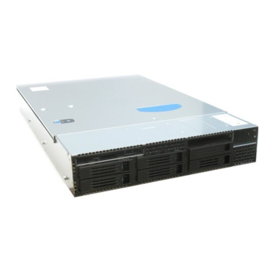
® The Intel Server Chassis SR2500 is a 2U server chassis that is designed to support the Intel Server Board S5000PAL. The server board and the chassis have features that are designed to support the high-density server market. This chapter provides a high-level overview of the chassis features. -
Page 14: Chassis Dimensions
0BProduct Overview Intel® Server System SR2500AL Chassis Dimensions Table 1. Chassis Dimensions Height 87.30 mm 3.44” Width without rails 430 mm 16.93” Width with rails 451.3 mm 17.77” Depth without CMA 704.8 mm 27.75” Depth with CMA 838.2 mm 33.0”... -
Page 15: System Boards
Intel® Server System SR2500AL 0BProduct Overview The I/O connector locations on the back of the chassis are pre-cut, so the use of an I/O shield is not required. The supplied EMI gasket must be installed to maintain Electromagnetic Interference (EMI) compliance levels. -
Page 16: Control Panel Options
Control Panel Options ® The chassis can support either of two control panels: a Standard Control Panel and an Intel Local Control Panel with LCD support. The control panel assemblies are pre-assembled and modular in design. The entire module assembly slides into a predefined slot in the front of the chassis. -
Page 17: Figure 7. Standard Control Panel Overview
Intel® Server System SR2500AL 0BProduct Overview The standard control panel supports several push buttons and status LEDs, along with USB and video ports to centralize system control, monitoring, and accessibility. The following diagram overviews the layout and functions of the control panel. -
Page 18: Figure 8. Lcd Control Panel Overview
0BProduct Overview Intel® Server System SR2500AL ® The Intel Local Control Panel utilizes a combination of control buttons, LEDs, and an LCD display to provide system accessibility, monitoring, and control functions. The following diagram provides an overview of this control panel. -
Page 19: Hard Drive And Peripheral Bays
Intel® Server System SR2500AL 0BProduct Overview Hard Drive and Peripheral Bays The chassis is designed to support several different hard drive and peripheral configurations. The system includes a hot swap backplane capable of supporting either SAS or SATA drives. The sixth bay (see letter “B” in the figure below) can optionally be configured to support a sixth hard drive or 3.5”... -
Page 20: System Cooling
0BProduct Overview Intel® Server System SR2500AL Each power supply module operates within the following voltage ranges and ratings: Start-up Power Max Rated Max Input PARAMETER RATED Input AC AC Current Current Line Voltage 85Vac 75Vac 100-127 V 140V 12 A 11.0A... -
Page 21: 1.11 Front Bezel Features
Intel® Server System SR2500AL 0BProduct Overview 1.11 Front Bezel Features The optional front bezel is made of molded plastic and uses a snap-on design. When installed, its design allows for maximum airflow to maintain system cooling requirements. TP02100 Figure 10. Optional Front Bezel Separate front bezels are available to support systems that use either a standard control panel ®... -
Page 22: Figure 12. Front Bezel Supporting Intel Local Control Panel
When the local control panel is used, the control panel module can be adjusted to extend further out from the chassis face to allow the LCD panel to protrude from the front bezel. AF000054 ® Figure 12. Front Bezel Supporting Intel Local Control Panel Revision – 1.6 Intel order number D31980-009... -
Page 23: Power Sub-System
Intel® Server System SR2500AL 1BPower Sub-System Power Sub-System The power sub-system of the chassis consists of an integrated Power Distribution Module (PDM), a power module enclosure, and support for up to two 750 Watt power supply modules. The power sub-system can be configured to support a single module in a 1+0 non-redundant configuration, or dual modules in a 1+1 redundant power configuration. -
Page 24: Single Power Supply Module Population
1BPower Sub-System Intel® Server System SR2500AL Single Power Supply Module Population In single power module configurations, server management firmware requires that the power supply module be populated in the top power module slot. The non-operating slot must have the power supply blank installed. -
Page 25: Airflow
Intel® Server System SR2500AL 1BPower Sub-System Airflow Each power supply module incorporates two non-redundant 40mm fans for self cooling and partial system cooling. The fans will provide no less than 10 CFM airflow through the power supply when installed in the system and operating at maximum fan speed. The cooling air will enter the power module from the PDB side (pre-heated air from the system). -
Page 26: P1 - Server Board Power Connector
1BPower Sub-System Intel® Server System SR2500AL 2.7.1 P1 – Server Board Power Connector Connector housing: 24- Pin Molex* Mini-Fit Jr. 39-01-2245 or equivalent Contact: Molex Mini-Fit, HCS, Female, Crimp 44476 or equivalent Table 3. P1 Main Power Connector 18 AWG... -
Page 27: P3 - Power Signal Connector
Intel® Server System SR2500AL 1BPower Sub-System 2.7.3 P3 – Power Signal Connector Connector housing: 5-pin Molex 50-57-9705 or equivalent Contacts: Molex 16-02-0087 or equivalent Table 5. P3 Power Signal Connector SIGNAL 24 AWG COLORS I2C Clock (SCL) White/Green I2C Data (SDL) -
Page 28: Efficiency
1BPower Sub-System Intel® Server System SR2500AL 2.8.1 Efficiency The following table provides the required minimum efficiency level at various loading conditions. These are provided at three different load levels; 100%, 50% and 20%. Efficiency is tested over an AC input voltage range of 115VAC to 220VAC. -
Page 29: Ac Inrush
Intel® Server System SR2500AL 1BPower Sub-System 2.8.5 AC Inrush AC line inrush current shall not exceed 40A peak for up to one-quarter of the AC cycle, after which, the input current should be no more than the specified maximum input current. The peak inrush current shall be less than the ratings of its critical components (including input fuse, bulk rectifiers, and surge limiting device). -
Page 30: Over-Temperature Protection (Otp)
1BPower Sub-System Intel® Server System SR2500AL Table 11. Over-Voltage Protection (OVP) Limits Output Voltage OVP MIN (V) OVP MAX (V) +3.3V +5VSB -12V -13.3 -14.5 +12V1/2/3/4 13.0 14.5 2.9.3 Over-Temperature Protection (OTP) The power supply will be protected against over-temperature conditions caused by loss of fan cooling or excessive ambient temperature. -
Page 31: 2.11 Power Supply Status Led
Intel® Server System SR2500AL 1BPower Sub-System 2.11 Power Supply Status LED Each power supply module will have a single bi-color LED to indicate power supply status. The LED operation is defined below. Table 12. LED Indicators Power Supply Condition Bi-Color LED... -
Page 32: Cooling Sub-System
2BCooling Sub-System Intel® Server System SR2500AL Cooling Sub-System Several components and configuration requirements make up the cooling sub-system of the chassis. These include the system fan module, the power supply fans, air baffles, CPU air duct, and drive bay population. All are necessary to provide and regulate the air flow and air pressure needed to maintain the system’s thermals when operating at or below maximum specified... -
Page 33: Non-Redundant Fan Module
Intel® Server System SR2500AL 2BCooling Sub-System Non-redundant Fan Module TP02119 Figure 15. Non-Redundant Fan Module This option provides the primary airflow for system configurations that do not require redundant cooling. Table 13 Nonredundant Cooling Zones Cooling Description of greatest cooling influence... -
Page 34: Figure 16. Non-Redundant Fan Header Assignments On Mid-Plane
2BCooling Sub-System Intel® Server System SR2500AL • Each fan has an associated fault LED on the mid-plane located next to the fan header. In the event of a fan failure, the fault LED for the failing fan can be illuminated by system management. -
Page 35: Redundant System Fan Module
Intel® Server System SR2500AL 2BCooling Sub-System Table 15. Nonredundant Fan Header Assignment Fan ID Mid-plane Fan Header Name Fan #1 - CPU1 cooling FAN_2 Fan #2 - CPU2 cooling FAN_4 Fan #3 - PCI Cooling FAN_5 Redundant System Fan Module TP02102 Figure 17. -
Page 36: Figure 18. Redudant Fan Header Assignments On Mid-Plane
2BCooling Sub-System Intel® Server System SR2500AL Table 17 Redundant Fan Connector Pin Assingment Signal Name Description Tachometer B Reserved, unused by redundant fan Fan speed control signal Power for fan Power for fan Tachometer A Fan RPM sensor output Two pulses per revolution for the 80mm fan... -
Page 37: Air Flow Support
Intel® Server System SR2500AL 2BCooling Sub-System Table 18 Redundant Fan Header Assignment Fan ID Mid-plane Fan Header Name Fan #1 - CPU1 Cooling FAN_1 Fan #2 - CPU1 Cooling FAN_2 Fan #3 - CPU2 Cooling FAN_3 Fan #4 - CPU2 Cooling... -
Page 38: Cpu / Memory / Low Profile Pci Zone
2BCooling Sub-System Intel® Server System SR2500AL 3.3.3 CPU / Memory / Low Profile PCI Zone The CPU / memory / low profile PCI zone is the area between the low profile riser card of the riser assembly and the right chassis wall. In a non-redundant fan configuration, the air flow for this zone is generated by system fans 1 and 2 of the fan module. -
Page 39: Platform Control
System BIOS BMC Firmware Sensor Data Records as loaded by the FRUSDR Utility FBDIMM type Processor type ® For additional details on platform control, please see the Intel S5000 Server Board Family Datasheet Revision – 1.6 Intel order number D31980-009... -
Page 40: System Board Interconnects
Mid-plane The mid-plane is new to this generation of Intel high density server platforms. Its design and use, along with that of the bridgeboard and hot-swap backplane, improve cable routing within the system. -
Page 41: Figure 22. Sas/Sas Raid Mid-Plane Board
Intel® Server System SR2500AL 4BSystem Board Interconnects The chassis also supports an active SAS / SAS RAID mid-plane. This system board incorporates an LSI* LSISAS1068 SAS controller onto the board. See Chapter 5 for details describing SAS / SAS RAID support. The following diagram shows the location for each connector found on this board. - Page 42 4BSystem Board Interconnects Intel® Server System SR2500AL SIGNAL NAME SIGNAL NAME PE1_ESB_TX_DN1 PE1_ESB_TX_DP1 FAN_PRSNT4_N RST_PS_PWRGD PE1_ESB_RX_DN_C1 PE1_ESB_RX_DP_C1 PE1_ESB_TX_DN0 PE1_ESB_TX_DP0 RAID_KEY_PRES FM_RAID_MODE PE1_ESB_RX_DN_C0 PE1_ESB_RX_DP_C0 CLK_IOP_DN CLK_IOP_DP FAN_PRSNT1_N FAN_PRSNT3_N SGPIO_DATAOUT1 FAN_PRSNT2_N SGPIO_DATAOUT0 SGPIO_LOAD USB1_ESB_DP SGPIO_CLOCK USB1_ESB_DN USB2_ESB_DP USB1_ESB_OC_N USB2_ESB_DN USB0_ESB_OC_N USB2_ESB_OC_N USB0_ESB_DP...
-
Page 43: Table 20. Mid-Plane Fan Header Pin-Outs
Intel® Server System SR2500AL 4BSystem Board Interconnects Table 20. Mid-plane Fan Header Pin-outs J2B1 - FAN_1 J2B3 - FAN_3 J7B1 - FAN_5 SIGNAL NAME SIGNAL NAME SIGNAL NAME FAN_TACH5 FAN_TACH7 FAN_TACH10 FAN_PWM_CPU1 FAN_PWM_CPU2 FAN_PWM3 P12V P12V P12V P12V P12V P12V... -
Page 44: Table 22. Mid-Plane-To-Backplane Card Edge Connector #1 Pin-Out
4BSystem Board Interconnects Intel® Server System SR2500AL Table 22. Mid-plane-to-Backplane Card Edge Connector #1 Pin-out J7A1 - HSBP#1 I/F SIGNAL NAME SIGNAL NAME RST_PS_PWRGD SATA0_RX_N SATA0_RX_P SATA1_RX_N SATA1_RX_P SATA0_TX_N SATA0_TX_P SATA1_TX_P SATA1_TX_N USB2_ESB_DN USB2_ESB_DP USB2_ESB_OC_N SATA2_RX_N SATA2_RX_P SATA3_RX_N SATA3_RX_P NC_RESERVEDB16... -
Page 45: Table 23. Mid-Plane-To-Backplane Card Edge Connector #2 Pin-Out
Intel® Server System SR2500AL 4BSystem Board Interconnects Table 23. Mid-plane-to-Backplane Card Edge Connector #2 Pin-out J4A1 - HSBP#2 I/F SIGNAL NAME SIGNAL NAME SGPIO_DATAOUT0 SGPIO_CLOCK SGPIO_DATAOUT1 SATA_ADDIN1_RX_N SATA_ADDIN1_RX_P SATA_ADDIN2_RX_N SATA_ADDIN2_RX_P SATA_ADDIN1_TX_N SATA_ADDIN1_TX_P SATA_ADDIN2_TX_P SATA_ADDIN2_TX_N SGPIO_LOAD SMB_PBI_3VSB_DAT SMB_IPMB_5VSB_DAT SMB_PBI_3VSB_CLK SMB_IPMB_5VSB_CLK USB0_ESB_OC_N... -
Page 46: Table 24. Active Mid-Plane Sas Raid Battery Backup Connector Pin-Out
4BSystem Board Interconnects Intel® Server System SR2500AL Table 24. Active Mid-plane SAS RAID Battery Backup Connector Pin-out Signal Description P12V NC_P5V_MONITOR P1V8_VBAT_RAID PWRGD_P3V3_STBY P1V8_VBAT_RAID PX_RESET_N SMB_CLK_P3V3 SMB_DAT_P3V3 BBU_PFAIL_N BBU_DDR_SEL BBU_BBE BBU_BBSTROBE BBU_BBSTATUS Table 25. Passive Mid-plane SATA/SAS Connector Pin-outs J5A2 - SAS_7... -
Page 47: Figure 22. Active Sas/Sas Raid Midplane 2 Board
Intel® Server System SR2500AL 4BSystem Board Interconnects AF002790 Optional RAID Cache Battery Fan 4 Connector Backup Connection Power Connector Fan 3 Connector Mini-DIMM Connector Fan 1 Connector Fan 6 Connector Fan 2 Connector RAID Activation Key Fan 5 Connector Connector... -
Page 48: Bridge Board
4BSystem Board Interconnects Intel® Server System SR2500AL Bridge Board The chassis utilizes a bridge board to route signals from the server board to the mid-plane board. The bridge board carries signals for three USB ports, SSI front panel control signals, video, various I2C buses, fan control signals, and a PCIe* x4 bus for SAS controller function. -
Page 49: Figure 24. Hot-Swap Sas/Sata Backplane (Front Side View)
Intel® Server System SR2500AL 4BSystem Board Interconnects AF000045 Figure 25. Hot-Swap SAS/SATA Backplane (Front Side View) Slimline Optical Drive Connector Control Panel Connector USB Floppy Connector SAS/SATA Hot Swap Connectors AF000044 Figure 26. Hot-Swap SAS/SATA Backplane (Back Side View) Power Connector (for 6... -
Page 50: Table 26. 2X4 Sas/Sata Backplane Power Connector Pin-Out (J7L2)
4BSystem Board Interconnects Intel® Server System SR2500AL Table 26. 2x4 SAS/SATA Backplane Power Connector Pin-out (J7L2) Pin # Signal Name Ground Ground P12V P12V P5V_STBY P3V3 Table 27. 1x7 6th HDD / Tape Drive Option Power Connector Pin-out (J2M1) Pin #... -
Page 51: Table 30. Slim-Line Optical Drive Slot Connector (J1A1)
Intel® Server System SR2500AL 4BSystem Board Interconnects Pin # Signal Name Pin # Signal Name RIDE_DD <15..0> 13 RIDE_DA2 RIDE_DD <15..0> 1 RIDE_DCS1_N RIDE_DD <15..0> 14 RIDE_DCS3_N RIDE_DD <15..0> 0 LED_IDE_L RIDE_DD <15..0> 15 Ground Ground Not Used Not Used... -
Page 52: Table 32. I2C Connector (J6L3)
4BSystem Board Interconnects Intel® Server System SR2500AL Table 32. I2C Connector (J6L3) Pin # Signal Description SMB_VSC_12C_DAT0 GROUND SMB_VSC_12C_CLK0 Not Used Table 33. PCIe X4 Slot Connector from Mid-plane (J4N1) Signal Name Signal Name SGPIO_DATA0 SGPIO_CLOCK SGPIO_DATA1 Ground Ground SAS6_RX_DN... -
Page 53: Table 34. Pcie* X4 Slot Connector From Mid-Plane (J6N1)
Intel® Server System SR2500AL 4BSystem Board Interconnects Table 34. PCIe* X4 Slot Connector from Mid-plane (J6N1) Signal Name Signal Name RST_PWRGD_PS Ground Ground SAS0_RX_DN Ground SAS0_RX_DP SAS1_RX_DN Ground SAS1_RX_DP Ground Ground SAS0_TX_DN Ground SAS0_TX_DP SAS1_TX_DP Ground SAS1_TX_DN Ground Ground USB_P3N... -
Page 54: Table 36. Intel Local Control Panel (Lcp) Connector (J9A1)
4BSystem Board Interconnects Intel® Server System SR2500AL ® Table 36. Intel Local Control Panel (LCP) Connector (J9A1) Pin # Signal Description SMB_IPMB_5VSB_DAT Ground SMB_IPMB_5VSB_CLK P5V_STBY_R Table 37. Control Panel Slot Connector (J9B1) Pin # Signal Name Pin # Signal Name... -
Page 55: Table 38. Sas/Sata Hard Drive Connector Pin-Outs (J2C3, J2B1, J4C1, J4B1, J7C1)
Intel® Server System SR2500AL 4BSystem Board Interconnects Table 38. SAS/SATA Hard Drive Connector Pin-outs (J2C3, J2B1, J4C1, J4B1, J7C1) Pin# Signal Description Ground SAS#_TX_DP (# = 0…4) SAS#_TX_DN (# = 0…4) Ground SAS#_RX_DN (# = 0…4) SAS#_RX_DP (# = 0…4) -
Page 56: Peripheral And Hard Drive Sub-System
The chassis provides a slim-line drive bay that is designed to support a single slim-line IDE ® optical drive or USB Floppy Drive. A list of supported drives can be found in the Intel Server Board S5000PAL/S5000XAL Tested Hardware and OS List. Either drive type is mounted to a tool-less tray which allows for easy installation into and removal from the chassis. -
Page 57: Figure 28. 50-Pin Connector To Slimline Optical Device
Intel® Server System SR2500AL 5BPeripheral and Hard Drive Sub-System The IDE Optical drive assembly includes an interposer board which plugs into the back of the optical drive. The interposer board is a card-edge type card that eliminates the need for cable connections. -
Page 58: Hard Drive Bays
5BPeripheral and Hard Drive Sub-System Intel® Server System SR2500AL The USB floppy drive assembly includes a USB cable which plugs into the back of the USB floppy drive and is then routed to the backplane’s 4-pin USB connector J2A1 (See Table 35. -
Page 59: Optional Tape Drive Or 6 Th Hard Drive Flex Bay
Intel® Server System SR2500AL 5BPeripheral and Hard Drive Sub-System Optional Tape Drive or 6 Hard Drive Flex Bay For system configurations that require either a Tape Drive or a 6 hard disk drive, a dual purpose drive bay is provided. By default this drive bay is covered by two face plates as shown in the following diagram. -
Page 60: Mid-Plane Options
5BPeripheral and Hard Drive Sub-System Intel® Server System SR2500AL Mid-plane Options New to this generation of high density server platform is the concept of the mid-plane. The mid- plane is the interconnect between the server board and both the hot-swap backplane and control panel. -
Page 61: Active Mid-Plane With Sas /Sas Raid Support
The active mid-plane is used to provide SAS / SAS RAID support. It has integrated on to it an Intel IOP80333 IO processor and an LSI* LSLSAS1068 3Gb/s SAS controller. Together they provide support for up to six SAS drives in this chassis. By default, this mid-plane option ®... - Page 62 5BPeripheral and Hard Drive Sub-System Intel® Server System SR2500AL AF002790 RAID Battery Backup Unit Fan 4 Connector Connector Power Connector Fan 3 Connector Mini-DIMM Connector Fan 1 Connector Fan 6 Connector Fan 2 Connector RAID Activation Key Fan 5 Connector...
-
Page 63: Figure 34. Architecture Overview
6.4.3.3 IOP80333 IO processor ® The Intel 80333 IO processor is a multi-function device that integrates the Intel Xscale core with intelligent peripherals and two PCIe* to PCI-X* bridges. It will be connected to the server board’s x4 PCIe lane and serve as bridge for PCI-X 133MHz secondary bus. The IOP80333 also includes fully functional RAID support. -
Page 64: Hot-Swap Sas/Sata Backplane
RAID support include an Intel RAID Activation Key (product order code - AXXRAK18E) and installation of a Mini-DIMM for Intel RAID Cache support. To protect from ® data loss during an unexpected power loss event, an Intel RAID Smart Battery Backup module (AXXRSBBU3) is also supported. -
Page 65: Sas/Sata Backplane Layout
Intel® Server System SR2500AL 5BPeripheral and Hard Drive Sub-System • Card edge connectors for most interconnects, including: o Mid-plane o Control Panel o Slim-line IDE Optical Drive • Temperature Sensor • FRU EEPROM • One 2x4-pin Power Connector 6.5.1 SAS/SATA Backplane Layout The hot-swap backplane installs on the back side of the hot-swap drive bay inside the chassis. - Page 66 5BPeripheral and Hard Drive Sub-System Intel® Server System SR2500AL AF000044 Figure 38. Hot-swap SAS/SATA Backplane (Back Side View) Power Connector (for 6 Hard Drive or Power Connector Tape Drive) SAS/SATA Connector (for 6 Hard Midplane Connectors Drive or SATA Tape Drive)
-
Page 67: Sas/Sata Backplane Functional Architecture
Intel® Server System SR2500AL 5BPeripheral and Hard Drive Sub-System 6.5.2 SAS/SATA Backplane Functional Architecture The figure below shows the functional blocks of the SAS/SATA backplane. LM75 I2C Bus0 EEPROM I2C Bus1 I2C Connector HBA Connector VSC410 I2C Bus2 SEEPROM BUS SW... -
Page 68: Table 40. Hard Drive Led Function Definitions
5BPeripheral and Hard Drive Sub-System Intel® Server System SR2500AL 6.5.2.1 Enclosure Management Controller The backplane utilizes the features of the Vitesse* VSC410 to implement several enclosure management functions. The chip provides in-band SAF-TE and SES management and utilizes the four I C interfaces listed below. -
Page 69: Standard Control Panel
Intel® Server System SR2500AL 6BStandard Control Panel Standard Control Panel The standard control panel supports several push buttons and status LEDs, along with USB and video ports to centralize system control, monitoring, and accessibility to within a common compact design. -
Page 70: Control Panel Led Indicators
6BStandard Control Panel Intel® Server System SR2500AL Table 42. Control Button and Intrusion Switch Functions Reference Feature Function Power / Toggles the system power on/off. This button also functions as a Sleep Sleep Button Button if enabled by an ACPI-compliant operating system. -
Page 71: Table 43. Control Panel Led Functions
Intel® Server System SR2500AL 6BStandard Control Panel The following table identifies each LED and describes their functionality. Table 43. Control Panel LED Functions Color State Description NIC1 / NIC2 Green NIC Link Activity Green Blink NIC Activity Green Legacy power on / ACPI S0 state... -
Page 72: Power / Sleep Led
6BStandard Control Panel Intel® Server System SR2500AL 7.2.1 Power / Sleep LED Table 44. SSI Power LED Operation State Power Mode Description Power Off Non-ACPI System power is off, and the BIOS has not initialized the chipset. Power On Non-ACPI System power is on, but the BIOS has not yet initialized the chipset. -
Page 73: Drive Activity Led
Intel® Server System SR2500AL 6BStandard Control Panel Amber Solid on Critical, non- Fatal alarm – system has failed or shutdown DIMM failure when there is one DIMM present, no good recoverable memory present Run-time memory uncorrectable error in non-redundant mode ... -
Page 74: Control Panel Connectors
6BStandard Control Panel Intel® Server System SR2500AL Control Panel Connectors The control panel has two external I/O connectors: • One USB port • One VGA video port The following tables provide the pin-outs for each connector. Table 46. External USB Connectors (J1B1) -
Page 75: Internal Control Panel Interconnect
Intel® Server System SR2500AL 6BStandard Control Panel Internal Control Panel Interconnect All control panel signals are directed through a single 64-pin card edge connector eliminating the need for any cables. When installed into the chassis control panel bay, the control panel card edge connector is blind mated with a slot connector on the backplane. -
Page 76: Table 48. 64-Pin Control Panel Connector (J6B1)
6BStandard Control Panel Intel® Server System SR2500AL The following table defines the pin-out for the 64-pin edge connector. Table 48. 64-pin Control Panel Connector (J6B1) SIGNAL NAME SIGNAL NAME 1_WIRE_BUS VGA_VSYNC_FP_L VGA_HSYNC_FP_L VGA_INUSE_L VGA_BLUE_FP P5V_STBY VGA_GREEN_FP FAULT_LED_5VSB VGA_RED_FP FP_SYS_FLT_LED1_R_L FP_ID_SW_L... -
Page 77: Intel Local Control Panel
® matching slot edge connector on the backplane eliminating any cable attachments. The Intel Local Control Panel module is designed so that it can be adjusted for use with or without an outer front bezel. -
Page 78: Led Functionality
7BIntel® Local Control Panel Intel® Server System SR2500AL LED Functionality The following table identifies each LED and describes their functionality. Table 49. Control Panel LED Functions Color State Description NIC1 / NIC2 Green NIC Link Activity Green Blink NIC Activity... -
Page 79: Power / Sleep Led
Intel® Server System SR2500AL 7BIntel® Local Control Panel 8.1.1 Power / Sleep LED Table 50. SSI Power LED Operation State Power Mode Description Power Off Non-ACPI System power is off, and the BIOS has not initialized the chipset. Power On Non-ACPI System power is on, but the BIOS has not yet initialized the chipset. -
Page 80: Drive Activity Led
7BIntel® Local Control Panel Intel® Server System SR2500AL Amber Solid on Critical, non- Fatal alarm – system has failed or shutdown DIMM failure when there is one DIMM present, no good recoverable memory present Run-time memory uncorrectable error in non-redundant mode ... -
Page 81: Intel ® Local Control Panel Interconnects
Intel® Server System SR2500AL 7BIntel® Local Control Panel ® Intel Local Control Panel Interconnects ® The Intel Local Control Panel module includes the control panel interface board and an interposer board. Connectors on the control panel interface board are cabled to matching connectors on the interposer board. -
Page 82: Table 53. Internal Usb Header
7BIntel® Local Control Panel Intel® Server System SR2500AL SIGNAL NAME SIGNAL NAME PWR_FP_USB2 HDD_FAULT_LED_R_L PWR_FP_USB3 HDD_LED_ACT_R_L FP_PWR_LED_R_L FP_SYS_FLT_LED2_R_L USB_DP3_FP USB_DN3_FP NC_RST_P6_PWRGOOD Table 53. Internal USB Header Pin # Description PWR_FP_USB2 PWR_FP_USB3 USB_DP2_FP USB_DN2_FP USB_DP3_FP USB_DN3_FP TP_USB0_P9 TP_USB0_P10 Revision – 1.6... -
Page 83: Pci Riser Cards And Assembly
Intel® Server System SR2500AL 8BPCI Riser Cards and Assembly PCI Riser Cards and Assembly The chassis supports different riser card options depending on the add-in card configuration desired. The riser assembly for the chassis is tool-less. Stand-offs on the bracket allow the riser cards to slide onto the assembly where a latching mechanism than holds each riser in place. -
Page 84: Riser Card Options
® The full height riser slot (J4F1) implements Intel Adaptive Slot Technology. This 280-pin connector is capable of supporting riser cards that meet either the PCI-X* or PCI Express* technology specifications. -
Page 85: Pci Riser Card Mechanical Drawings
Intel® Server System SR2500AL 8BPCI Riser Cards and Assembly Full Height Riser 1 add-in card 2 add-in cards 3 add-in cards PCI Express* (Product Order Code – ASR2500FHR) 2U – 3 add-in card slots Single PCIe* x4 in top slot Single PCIe –... - Page 86 8BPCI Riser Cards and Assembly Intel® Server System SR2500AL Ø 8.26 [0.325] Both Side 5.00 Ground Pad [0.197] Ø 6.00 3.50 [0.138] [0.236] R2.00 [0.079] Ø 3.50 [0.138] Detail A Scale 2.000 4X Side 1 See Detail A No Component 5X R1.00 [0.039]...
- Page 87 Intel® Server System SR2500AL 8BPCI Riser Cards and Assembly Ø 8.26 [0.325] Both Side 5.00 Ground Pad [0.197] Ø 6.00 3.50 [0.138] [0.236] R2.00 [0.079] Ø 3.50 [0.138] Detail A Scale 2.000 See Detail A 5X R1.00 [0.039] Side 2 Ground Pad 74.75 [2.943]...
- Page 88 8BPCI Riser Cards and Assembly Intel® Server System SR2500AL See Detail A R1.00 [0.039] Side 2 Ground Pad 74.75 [2.943] 70.50 [2.776] 72.84 [2.868] 67.67 [2.664] 68.90 [2.713] 58.18 [2.291] 56.63 [2.230] 52.52 [2.068] 38.39 [1.508] 35.40 [1.394] See Detail B 32.20 [1.268]...
-
Page 89: 10. Supported Intel
5000P Memory Controller Hub or Intel 5000X Memory Controller Hub 6321ESB I/O Controller Hub 1 ® Intel ® Note: Intel will only make available an OEM SKU of this server board using the Intel 5000X Memory Controller Hub. On-board External connections: Connectors/Headers... - Page 90 9BSupported Intel® Server Boards Intel® Server System SR2500AL V U S TP02071 ® Figure 51. Intel Server Board S5000PAL Revision – 1.6 Intel order number D31980-009...
-
Page 91: Processor Support
Server Board S5000PAL Components 10.1.1 Processor Support ® ® The server system supports one or two Dual-Core Intel Xeon processors 5000 sequence, with system bus speeds of 667 MHz, 1066 MHz, and 1333 MHz, and core frequencies starting at ®... -
Page 92: 11. Environmental And Regulatory Specifications
Vibration, unpackaged 5 Hz to 500 Hz, 2.20 g RMS random Shock, operating Half sine, 2 g peak, 11 mSec +/-15kV except I/O port +/-8KV per Intel Environmental test specification System Cooling 3264 BTU/hour Requirement in BTU/Hr 11.2 Serviceability and Availability The system is designed to be serviced by qualified technical personnel only. -
Page 93: 11.3 Replacing The Back Up Battery
Intel® Server System SR2500AL 10BEnvironmental and Regulatory Specifications 11.3 Replacing the Back up Battery The lithium battery on the server board powers the real time clock (RTC) for up to 10 years in the absence of power. When the battery starts to weaken, it loses voltage, and the server settings stored in CMOS RAM in the RTC (for example, the date and time) may be wrong. -
Page 94: 11.4 Product Regulatory Compliance
URL: http://channel.intel.com/go/serverbuilder If you do not have access to Intel’s Web address, please contact your local Intel representative. Server chassis (base chassis is provided with power supply and fans)⎯UL listed. Server board⎯you must use an Intel server board—UL recognized. -
Page 95: Table 55. Product Safety & Electromagnetic (Emc) Compliance
Intel® Server System SR2500AL 10BEnvironmental and Regulatory Specifications Table 55. Product Safety & Electromagnetic (EMC) Compliance Compliance Regional Compliance Compliance Reference Marking Example Description Reference Australia / New Zealand AS/NZS 3548 (Emissions) N232 Argentina IRAM Certification (Safety) Belarus Belarus Certification... -
Page 96: 11.6 Electromagnetic Compatibility Notices
10BEnvironmental and Regulatory Specifications Intel® Server System SR2500AL Compliance Regional Compliance Compliance Reference Marking Example Description Reference Ukraine Ukraine Certification None Required Taiwan BSMI CNS13438 R33025 11.6 Electromagnetic Compatibility Notices 11.6.1 This device complies with Part 15 of the FCC Rules. Operation is subject to the following two conditions: (1) this device may not cause harmful interference, and (2) this device must accept any interference received, including interference that may cause undesired operation. -
Page 97: Fcc Verification Statement
Intel® Server System SR2500AL 10BEnvironmental and Regulatory Specifications 11.6.2 FCC Verification Statement Product Type: SR2500; S5000PAL This device complies with Part 15 of the FCC Rules. Operation is subject to the following two conditions: (1) This device may not cause harmful interference, and (2) this device must accept any interference received, including interference that may cause undesired operation. -
Page 98: Bsmi (Taiwan)
English translation of the notice above: 1. Type of Equipment (Model Name): On License and Product 2. Certification No.: On RRL certificate. Obtain certificate from local Intel representative 3. Name of Certification Recipient: Intel Corporation 4. Date of Manufacturer: Refer to date code on product 5. -
Page 99: 11.7 Product Ecology Compliance
Intel® Server System SR2500AL 10BEnvironmental and Regulatory Specifications 11.7 Product Ecology Compliance Intel has a system in place to restrict the use of banned substances in accordance with world wide product ecology regulatory requirements. The following is Intel’s product ecology compliance criteria. - Page 100 German Green Dot Applied to Retail Packaging Only for Boxed Boards Intel Internal All materials, parts and subassemblies must not Specification contain restricted materials as defined in Intel’s Environmental Product Content Specification of None Required Suppliers and Outsourced Manufacturers – http://supplier.intel.com/ehs/environmental.htm International ISO11469 - Plastic parts weighing >25gm are...
-
Page 101: 11.8 Other Markings
Intel® Server System SR2500AL 10BEnvironmental and Regulatory Specifications 11.8 Other Markings Compliance Compliance Reference Compliance Reference Description Marking Example Stand-by Power 60950 Safety Requirement Applied to product is stand-by power switch is used. English: Multiple Power Cords 60950 Safety Requirement... - Page 102 10BEnvironmental and Regulatory Specifications Intel® Server System SR2500AL < This page intentionally left blank > Revision – 1.6 Intel order number D31980-009...
-
Page 103: Appendix A: Chassis Integration And Usage Tips
In order to remove or replace the Mid-plane board, the fan cage must first be removed. o There are three indentations in the top of the chassis. These are for the Intel Safety Label, the Windows Certification Label, and a Customer Defined Label. -
Page 104: Appendix B: Post Code Diagnostic Led Decoder
Appendix B: POST Code Diagnostic LED Decoder Intel® Server System SR2500AL Appendix B: POST Code Diagnostic LED Decoder During the system boot process, BIOS executes a number of platform configuration processes, each of which is assigned a specific hex POST code number. As each configuration routine is started, BIOS will display the given POST code to the POST Code Diagnostic LEDs found on the back edge of the server board. -
Page 105: Table 57. Diagnostic Led Post Code Decoder
Intel® Server System SR2500AL Appendix B: POST Code Diagnostic LED Decoder Table 57. Diagnostic LED POST Code Decoder Diagnostic LED Decoder Description Checkpoint G=Green, R=Red, A=Amber Host Processor 0x10h Power-on initialization of the host processor (bootstrap processor) 0x11h Host processor cache initialization (including AP) - Page 106 Appendix B: POST Code Diagnostic LED Decoder Intel® Server System SR2500AL Diagnostic LED Decoder Description Checkpoint G=Green, R=Red, A=Amber 0x92h Detecting the presence of the keyboard 0x93h Enabling the keyboard 0x94h Clearing keyboard input buffer 0x95h Instructing keyboard controller to run Self Test (PS2 only)
- Page 107 Intel® Server System SR2500AL Appendix B: POST Code Diagnostic LED Decoder Diagnostic LED Decoder Description Checkpoint G=Green, R=Red, A=Amber 0xE8h Checking password 0xE9h Entering BIOS setup 0xEAh Flash Update 0xEEh Calling Int 19. One beep unless silent boot is enabled.
-
Page 108: Appendix C: Post Error Beep Codes
The BMC may generate beep codes upon detection of failure conditions. Beep codes are sounded each time the problem is discovered, such as on each power-up attempt, but are not ® sounded continuously. Codes that are common across all Intel server boards and systems that ®... -
Page 109: Glossary
Intel® Server System SR2500AL Glossary Glossary Word / Acronym Definition Australian Communication Authority ANSI American National Standards Institute Baseboard Management Controller CMOS Complementary Metal Oxide Silicon DC-to-DC Emergency Management Port Front Panel Fault Resilient Boot Field Replaceable Unit Liquid Crystal Display... -
Page 110: Reference Documents
Reference Documents Intel® Server System SR2500AL Reference Documents See the following documents for additional information: ® o Intel Server Board S5000PAL Technical Product Specification ® o Intel 5000 Series Chipsets Server Board Family Datasheet ® o Intel Server Chassis SR2500 Power Distribution Board for 750W Power Supply Specification ®...
Need help?
Do you have a question about the SR1500 - AXXMINIDIMM DDR-2 RAID Controller Cache Memory and is the answer not in the manual?
Questions and answers