Table of Contents
Advertisement
Quick Links
Download this manual
See also:
Configuration Manual
Advertisement
Table of Contents

Related Manuals for Intel S9200WK Series


Summary of Contents for Intel S9200WK Series
- Page 1 Intel® Server System S9200WK Product Family Setup and Service Guide Initial system setup instructions and procedures for the installation and replacement of system components and available Intel accessories Rev 1.0 July 2019 Intel® Server Products and Solutions...
- Page 2 <This page is intentionally left blank>...
- Page 3 Intel® Server System S9200WK Product Family Setup and Service Guide Document Revision History Date Revision Changes July 2019 Initial release.
- Page 4 Copies of documents which have an order number and are referenced in this document may be obtained by calling 1-800-548-4725 or by visiting www.intel.com/design/literature.htm. Intel and the Intel logo are trademarks of Intel Corporation or its subsidiaries in the U.S. and/or other countries.
- Page 5 Intel recommends the following steps be taken when performing any procedures described within this document or while performing service to any computer system.
- Page 6 Caution: Slide/rail mounted equipment is not to be used as a shelf or a work space. Intel warranties that this product will perform to its published specifications. However, all computer systems are inherently subject to unpredictable system behavior under various environmental and other conditions.
- Page 7 Note: This requirement applies only to Intel® server system products released in 2019 or later. Legacy Intel® server system products (released in 2018 or earlier) provide safeguards that require no additional access restrictions.
-
Page 8: Table Of Contents
3.1.2 Removing the Intel® Virtual RAID on CPU (Intel® VROC) Upgrade Key ..........23 Intel® Remote Management Module 4 Lite (Intel® RMM4 Lite) Key – iPC AXXRMM4LITE2 .... 24 3.2.1 Installing the Intel® Remote Management Module 4 Lite (Intel® RMM4 Lite) Key ......24 3.2.2... - Page 9 Intel® Server System S9200WK Product Family Setup and Service Guide 4.5.4 M.2 Heat Sink Installation ............................ 41 System Battery Replacement ..........................42 Liquid Cooling Loop Replacement (Liquid Cooled Compute Modules Only) ........43 4.7.1 Liquid Cooling Loop Removal ..........................43 4.7.2...
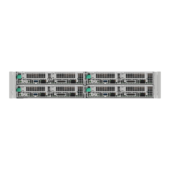
- Page 10 Intel® Server System S9200WK Product Family Setup and Service Guide List of Figures Figure 1. Liquid cooled system back view ..........................15 Figure 2. Air cooled system back view ............................15 Figure 3. Compute module identification – 4 node system with 1U compute modules ........... 16 Figure 4.
- Page 11 Intel® Server System S9200WK Product Family Setup and Service Guide Figure 41. Removing the cross head screws ..........................43 Figure 42. Removing the T-20 screws ............................43 Figure 43. Removing the liquid cooling loop ........................... 44 Figure 44. Securing the cross head screws ..........................45 Figure 45.
- Page 12 Intel® Server System S9200WK Product Family Setup and Service Guide Figure 83. DIMM population for liquid cooled compute modules with 8 DIMMs of up to 32GB capacity ..78 Figure 84. DIMM population for liquid cooled compute modules with 8 DIMMs of 64GB capacity ..... 79 Figure 85.
- Page 13 Intel® Server System S9200WK Product Family Setup and Service Guide List of Tables Table 1. System status LED state definitions .......................... 81 Table 2. POST progress code LED example ..........................83 Table 3. MRC progress codes ............................... 85 Table 4. MRC fatal error codes ..............................86 Table 5.
- Page 14 Intel® Server System S9200WK Product Family Setup and Service Guide <This page is intentionally left blank>...
-
Page 15: Introduction
Introduction The Intel® Server System S9200WK Product Family The Intel® Server System S9200WK is a density-optimized, rack-mounted, 2U, multi-node product family that is designed to support high-density, high-performance computing environments in both liquid and air cooled configurations. Each system within the Intel Server System S9200WK product family includes independent, pre-configured compute modules that allow for a power-on ready installation. -
Page 16: Figure 3. Compute Module Identification - 4 Node System With 1U Compute Modules
Intel® Server System S9200WK Product Family Setup and Service Guide Figure 3. Compute module identification – 4 node system with 1U compute modules Figure 4. Compute module identification – 2 node systems with 2U compute modules Figure 5. 1U compute module front panel feature identification... -
Page 17: Figure 6. 2U Compute Module Front Panel Feature Identification
Intel® Server System S9200WK Product Family Setup and Service Guide Figure 6. 2U compute module front panel feature identification Figure 7. Front control panel features Figure 8. I/O breakout cable connector identification... -
Page 18: System Setup
Compute Module Requirements for liquid cooled systems The liquid cooled systems within the Intel® Server System S9200WK product family are designed to operate while being connected to a non-Intel coolant distribution unit that supports Staubli* SCG 06 quick connect couplings. -
Page 19: Installing The System Into A Rack
Installing the Fixed Rail Kit The Intel® Server System S9200WK product family includes a fixed rail kit that serves as a shelf for the system upon installation into the rack. When a system is installed onto the fixed rails, it can be secured to both the rail and the rack through a pair of thumbscrews on the front of the system. -
Page 20: Installing The Chassis Into A Rack
Installing the Chassis Into a Rack Important Safety Note: Due to the weight of a fully configured system, Intel® recommends using a mechanical lift to aid with the installation of the system into the rack, and/or to use at least two people to install the system into the rack, or remove all installed compute modules from the system before attempting to install the system into the rack. -
Page 21: Connecting The System To A Liquid Coolant Supply
Each compute module within the Intel® Server System S9200WK product family includes a software stack that includes a BIOS, BMC firmware, Intel® Management Engine (Intel® ME) firmware, and both FRU and SDR data. A full software stack is installed during the system manufacturing process, but may not be the latest available version. -
Page 22: Optional Accessory Kit Integration And Service
Intel® Server System S9200WK Product Family Setup and Service Guide Optional Accessory Kit Integration and Service This chapter provides installation and removal instructions for supported optional accessory kits. Before Beginning Before working with the server product, observe the safety and ESD precautions found in the Warnings section at the beginning of this guide. -
Page 23: Intel® Virtual Raid On Cpu (Intel® Vroc) Upgrade Key - Ipc Vrocstanmod
Intel® Server System S9200WK Product Family Setup and Service Guide Intel® Virtual RAID on CPU (Intel® VROC) Upgrade Key – IPC VROCSTANMOD 3.1.1 Installing the Intel® Virtual RAID on CPU (Intel® VROC) Upgrade Key Figure 13. Installing the Intel® VROC Upgrade Key 1. -
Page 24: Intel® Remote Management Module 4 Lite (Intel® Rmm4 Lite) Key - Ipc Axxrmm4Lite2
2. Remove the right riser assembly from Riser Slot 2. (see Section 0) 3. Remove the Intel RMM4 Lite Key from its packaging. 4. Locate the Intel RMM4 Lite key connector near the right edge of the server board behind the RJ45 Management Port connector. -
Page 25: Pcie* Add-In Card
Intel® Server System S9200WK Product Family Setup and Service Guide PCIe* Add-In Card The following procedures are identical for both 1U and 2U riser card assemblies 3.3.1 Installing a PCIe* Add-In Card 1U riser card assembly shown** Figure 17. Installing an add-in card 1. -
Page 26: Ethernet Management Port Module (Emp Module) - Ipc Axxfcemp
Intel® Server System S9200WK Product Family Setup and Service Guide 1. Remove the compute module to be serviced from the server chassis and place it on to an anti-static work surface (see Section 4.2.1) 2. Remove the selected riser assembly from the compute module (see Section 0) 3. -
Page 27: Removing The Emp Module
Intel® Server System S9200WK Product Family Setup and Service Guide 3.4.2 Removing the EMP Module 1. Locate the EMP module on the back of the chassis. Figure 21. Removing the EMP module/blank 2. Remove the EMP module by pushing down on the Green latch (see Letter A) and then pulling it out from the chassis (see Letter B). -
Page 28: System Service
This chapter provides instructions for removing and installing system components considered field replaceable (field-replaceable units, or FRUs). The Intel® Server System S9200WK product family features a modular design, allowing for servicing of system fans, power supply modules, compute modules and Ethernet Management Port module (EMP module) without having to power off the entire system. -
Page 29: System Component Identification
Intel® Server System S9200WK Product Family Setup and Service Guide System Component Identification The following illustrations provide a quick reference to identify system components that are considered field serviceable. Refer to the Intel® Server System S9200WK product family Configuration Guide for a complete list of available spares. Number... -
Page 30: Figure 23. 1U Liquid Cooled Compute Module Component Identification
Intel® Server System S9200WK Product Family Setup and Service Guide Number Name Compute module tray with server board Liquid cooling loop DIMM retention clips Riser assemblies Figure 23. 1U liquid cooled compute module component identification... -
Page 31: Figure 24. 2U Liquid Cooled Compute Module Component Identification
Intel® Server System S9200WK Product Family Setup and Service Guide Number Name Compute module tray with server board Liquid cooling loop DIMM retention clips Riser assemblies Figure 24. 2U liquid cooled compute module component identification... -
Page 32: Figure 25. 2U Air Cooled Compute Module Component Identification
Intel® Server System S9200WK Product Family Setup and Service Guide Number Name Compute module tray with server board CPU Heat sinks Air duct Riser assemblies Figure 25. 2U air cooled compute module component identification... -
Page 33: Compute Module Replacement
Intel® Server System S9200WK Product Family Setup and Service Guide Compute Module Replacement All installed compute modules within an Intel® Server System S9200WK are independent from each other. Servicing a compute module does not require having to power down the full server system. Only the compute module to be serviced must be powered down before being removed from the server chassis. -
Page 34: Compute Module Installation
Intel® Server System S9200WK Product Family Setup and Service Guide 2. Press the green latch inward (see Letter A) and lower the lever in front of the compute module (see Letter B). 3. Grasp the lever and pull out the compute module from the chassis (see Letter C). -
Page 35: Riser Assembly Replacement
Intel® Server System S9200WK Product Family Setup and Service Guide Riser Assembly Replacement Before following the instructions in this section, remove the Intel® compute module (see Section 4.2.1) needing service. This procedure applies to both 1U and 2U compute modules. -
Page 36: Riser Assembly Installation
Drive Carrier Extraction, Assembly, and Installation The 2U compute modules of the Intel® Server System S9200WK product family have support for up to two hot-swap 2.5” form factor U.2 Solid State Drives (SSDs). Each drive installed to a tool-less drive carrier. This section provides instructions for drive extraction from the chassis, drive assembly, and drive installation into the chassis. -
Page 37: Drive Carrier Extraction
Intel® Server System S9200WK Product Family Setup and Service Guide 4.4.1 Drive Carrier Extraction Figure 30. Drive carrier extraction from the chassis 1. Press the button on the carrier face plate to release the lever (see Letter A). 2. Using the lever, pull the carrier from the drive bay (see Letter B). -
Page 38: Figure 32. 2.5" Drive Carrier Assembly - Drive Installation Into The Carrier
Intel® Server System S9200WK Product Family Setup and Service Guide Figure 32. 2.5” drive carrier assembly – drive installation into the carrier 2. Carefully unpack the new drive, taking care not to touch any of the connector pins located on the back side of the drive. -
Page 39: Drive Carrier Installation
Intel® Server System S9200WK Product Family Setup and Service Guide 4.4.3 Drive Carrier Installation Figure 34. Drive carrier installation into the chassis 1. Align the drive assembly with the open drive bay. 2. With the lever in the open position, insert the drive assembly into the drive bay (see Letter A) and push forward until the drive makes contact with the internal backplane. -
Page 40: M.2 Heat Sink Removal
Intel® Server System S9200WK Product Family Setup and Service Guide 4.5.1 M.2 Heat Sink Removal The riser assembly includes an M.2 heat sink that must be removed prior to servicing any M.2 SSD. 1U Riser Assembly 2U Riser Assembly Figure 35. Removing the M.2 heat sink 1. -
Page 41: M.2 Ssd Installation
Intel® Server System S9200WK Product Family Setup and Service Guide 4.5.3 M.2 SSD Installation 1U Riser Assembly 2U Riser Assembly Figure 37. Installing the M.2 SSD 1. If present, remove the screw from the M.2 mounting stand-off on the left side of the riser assembly. -
Page 42: System Battery Replacement
Intel® Server System S9200WK Product Family Setup and Service Guide System Battery Replacement Required Tools and Supplies: • Anti-static wrist strap and conductive foam pad (recommended) Before following the instructions in this section, remove the select compute module from the server chassis (see Section 4.2.1), and then remove the riser assemblies from the compute module (see Section 4.3.1). -
Page 43: Liquid Cooling Loop Replacement (Liquid Cooled Compute Modules Only)
Intel® Server System S9200WK Product Family Setup and Service Guide Liquid Cooling Loop Replacement (Liquid Cooled Compute Modules Only) Before following the instructions in this section, remove the selected compute module from the server chassis (see Section 4.2.1). Required Tools and Supplies: •... -
Page 44: Figure 43. Removing The Liquid Cooling Loop
Intel® Server System S9200WK Product Family Setup and Service Guide Figure 43. Removing the liquid cooling loop 3. Carefully lift the liquid cooling loop assembly up and away from the compute module. See Figure 43. -
Page 45: Liquid Cooling Loop Installation
Intel® Server System S9200WK Product Family Setup and Service Guide 4.7.2 Liquid Cooling Loop Installation 1. Carefully unpack the new liquid cooling loop. 2. Carefully place the liquid cooling loop assembly into the compute module, ensuring that both the DIMM cooling assembly and processor cold plates are properly aligned with the mounting screw holes. -
Page 46: Air Duct Replacement (Air Cooled Compute Modules Only)
Intel® Server System S9200WK Product Family Setup and Service Guide Air Duct Replacement (Air Cooled Compute Modules Only) 4.8.1 Air Duct Removal Figure 46. Removing the air duct 1. Remove the compute module to be serviced from the server chassis (see Section 4.2.1). -
Page 47: Processor Heat Sink Replacement (Air Cooled Compute Modules Only)
Intel® Server System S9200WK Product Family Setup and Service Guide Processor Heat Sink Replacement (Air Cooled Compute Modules Only) Due to possible damage to the server board while attempting to remove/install the processor heat sink, Intel does NOT recommend removing the processor heat sink outside of the following: •... -
Page 48: Processor Heat Sink Installation
Intel® Server System S9200WK Product Family Setup and Service Guide • No excess cleaning agent should flow from the top side of the processor onto any part of the server board 4.9.2 Processor Heat Sink Installation Figure 49. Installing the processor heat sink Note: Replacement processor heat sinks will include thermal interface material (TIM) on the bottom side of the heat sink. -
Page 49: 4.10 Memory (Dimm) Replacement
Intel® Server System S9200WK Product Family Setup and Service Guide 4.10 Memory (DIMM) Replacement This section documents the procedure to follow when replacement of a faulty DIMM is necessary. The DIMM replacement procedure for a liquid cooled compute module and an air cooled cooled compute module is different. -
Page 50: Liquid Cooled Compute Module Dimm Replacement
4.10.2.1 DIMM Removal The liquid cooled compute modules within the Intel® Server System S9200WK product family include a memory replacement tool located on top of the cold plates of the liquid cooling loop. This tool can be used to remove the DIMM retainer clips in memory configurations that require them, and to open the DIMM ejection tabs. -
Page 51: Figure 53. Removing The Dimm Retention Clips
Intel® Server System S9200WK Product Family Setup and Service Guide If the compute module does not have DIMM retention clips installed, skip to step 6. Figure 53. Removing the DIMM retention clips 3. Identify and locate the faulty DIMM 4. Use the memory removal tool as a lever and position one end between the DIMM retention clip and the liquid cooling loop (see Letter A). -
Page 52: Figure 55. Installing The Dimm In A Liquid Cooled System
Intel® Server System S9200WK Product Family Setup and Service Guide 4.10.2.2 DIMM Installation Figure 55. Installing the DIMM in a liquid cooled system 1. Locate the DIMM slot for installation. Ensuring that the DIMM ejection tabs at both ends of the DIMM slot are pushed outward to the open position (see Letter A). -
Page 53: Memory Heat Spreader Thermal Pad Replacement (Liquid Cooled Compute Modules Only)
Should a thermal pad become damaged while installing or removing a DIMM, or become damaged or worn for other reasons, the following sections provide the instructions necessary to remove and replace a heat spreader thermal pad. Note: To maintain optimal performance of the liquid cooling loop, Intel recommends replacing ALL thermal pads at once. 4.11.1 Thermal Pad Removal 1. -
Page 54: Thermal Pad Installation
Intel® Server System S9200WK Product Family Setup and Service Guide 4.11.2 Thermal Pad Installation Figure 58. Installing a thermal pad 1. Apply a new thermal pad to the heat spreader by aligning the thermal pad’s cutout edges with the heat spreader’s shape (see Letter A). -
Page 55: Power Supply Installation
Intel® Server System S9200WK Product Family Setup and Service Guide 1. Identify the faulty power supply. 2. Detach the power cord from the power supply to be removed. 3. While pushing the green latch in the shown direction (see Letter A), use the handle to pull the power supply module from the system fan assembly (see Letter B). -
Page 56: 4.13 System Fan Replacement
Intel® Server System S9200WK Product Family Setup and Service Guide 4.13 System Fan Replacement The Intel® Server System S9200WK product family supports two system fan configurations, one for Liquid Cooled configurations and one for Air Cooled configurations, as shown in the following illustrations. -
Page 57: System Fan Removal
Intel® Server System S9200WK Product Family Setup and Service Guide 4.13.1 System Fan Removal Figure 63. Removing the system fan 1. If present, remove the power supply (see Section 4.12.1) from the system fan assembly to be removed. 2. While pushing the green latch in the shown direction (see Letter A), use the handle to pull the system fan assembly out of the bay (see Letter B). -
Page 58: Chassis Plumbing Assembly Replacement (Liquid Cooled Systems Only)
1. Power the system down, remove it from the rack and place it on a flat surface. Important Safety Note: Due to the weight of a fully configured system, Intel® recommends using a mechanical lift to aid with the removal of the system from the rack, and/or to use at least two people to remove the system from the rack, or remove all installed compute modules from the system before attempting to remove the system from the rack. -
Page 59: Figure 66. Removing The Quick Connect Screws
Intel® Server System S9200WK Product Family Setup and Service Guide Figure 66. Removing the quick connect screws 2. Using a phillips head screwdriver, remove the four screws that secure each of the quick connect couplings to the covers. Figure 67. Removing quick connect covers 3. -
Page 60: Figure 69. Removing The Chassis Plumbing Assembly
Intel® Server System S9200WK Product Family Setup and Service Guide Figure 69. Removing the chassis plumbing assembly 6. Using a phillips head screwdriver remove the six screws on the top brace of the plumbing assembly and loosen the four captive screws on the sides of the brace (see Letter A). -
Page 61: Chassis Plumbing Assembly Installation
Intel® Server System S9200WK Product Family Setup and Service Guide 4.14.2 Chassis Plumbing Assembly Installation Figure 70. Installing the chassis plumbing assembly 1. Lower the plumbing assembly inside the chassis and slide the quick connect couplings into their respective bays (see Letter A). -
Page 62: Figure 71. Installing Quick Connect Covers
Intel® Server System S9200WK Product Family Setup and Service Guide Figure 71. Installing quick connect covers 3. Install the quick connect covers by sliding them into the chassis and then pressing downwards. Figure 72. Securing the quick connect couplings to the covers 4. -
Page 63: Figure 73. Installing The Quick Connect Fillers
Intel® Server System S9200WK Product Family Setup and Service Guide Figure 73. Installing the quick connect fillers 5. Insert the fillers above the quick connect couplings in the back of the chassis. 6. Install the system fans (see Section 4.13.2). -
Page 64: 4.15 Power Distribution Board (Pdb) Assembly Replacement
1. Power the system down and remove it from the rack. Important Safety Note: Due to the weight of a fully configured system, Intel® recommends using a mechanical lift to aid with the removal of the system from the rack, and/or to use at least two people to remove the system from the rack, or remove all installed compute modules from the system before attempting to remove the system from the rack. -
Page 65: Figure 76. Disconnecting The System Fan Power Cables
Intel® Server System S9200WK Product Family Setup and Service Guide Figure 76. Disconnecting the system fan power cables 4. Locate and disconnect the system fan power cables from the power distribution board by pressing inwards on each clip and lifting them up. -
Page 66: Figure 77. Removing The Power Distribution Board
Intel® Server System S9200WK Product Family Setup and Service Guide Figure 77. Removing the power distribution board 9. Remove the screws securing the power distribution board to the chassis with a phillips head screwdriver (see Letter A). 10. Remove the PDB by lifting it upwards, tilting up the front side of the PDB, and then lifting the board... -
Page 67: Power Distribution Board Assembly Installation
Intel® Server System S9200WK Product Family Setup and Service Guide 4.15.2 Power Distribution Board Assembly Installation Figure 78. Installing the power distribution board 1. Lower the PDB into the chassis, tilting down the back side and then sliding the board to the front (see Letter A). -
Page 68: Figure 79. Connecting System Fan Power Cables
Intel® Server System S9200WK Product Family Setup and Service Guide Figure 79. Connecting system fan power cables 7. Locate and connect the system fan cables by pressing inwards on each clip and pressing them down into the appropriate connector. -
Page 69: Figure 80. Securing The Back Cover
Intel® Server System S9200WK Product Family Setup and Service Guide Figure 80. Securing the back cover 8. Place the back cover over the top of the chassis and slide it towards the front (see Letter A). 9. Secure the back cover with a phillips head screwdriver and the four screws provided (see Letter B). -
Page 70: 4.16 Internal Chassis Rail Replacement
Intel® Server System S9200WK Product Family Setup and Service Guide 4.16 Internal Chassis Rail Replacement The systems within the Intel® Server System S9200WK product family include internal rails to support 1U compute modules in the upper part of the inner walls of the chassis. Should the internal rails become damaged or worn out, the following sections provide the instructions necessary to remove and replace them. -
Page 71: Internal Chassis Rail Installation
Intel® Server System S9200WK Product Family Setup and Service Guide 4.16.2 Internal Chassis Rail Installation Figure 82. Installing the internal chassis rail 1. Place the rail inside the chassis aligning the keying pins of the rail with the chassis inner wall. -
Page 72: System Packaging Assembly Instructions
Intel® Server System S9200WK Product Family Setup and Service Guide System Packaging Assembly Instructions The original Intel packaging is designed to provide protection to a fully configured system and tested to meet ISTA (International Safe Transit Association) Test Procedure 3A (2008). The packaging is also designed to be re-used. - Page 73 Intel® Server System S9200WK Product Family Setup and Service Guide 3. Wrap the red foam sheet around the system. 4. Install the red front foam in the front of the system (left piece in the illustration below) and the red...
- Page 74 Intel® Server System S9200WK Product Family Setup and Service Guide 5. Carefully place the system into the shipping bag and tape the bag shut. 6. Carefully lower the system into the inner shipping box as shown. 7. Put the front foam on the left top and the rear foam on the right top.
- Page 75 Intel® Server System S9200WK Product Family Setup and Service Guide 8. Place the accessory box in the middle as shown. 9. Fold the top flaps of the inner box closed, end flaps first, followed by side flaps. a. By design, the two side flaps will not meet. Do not tape side flaps shut.
- Page 76 Intel® Server System S9200WK Product Family Setup and Service Guide 10. Fold the top flaps of the outer box closed, end flaps first, followed by the side flaps. 11. Tape the outer box using an H-pattern. Across the center first, followed by both ends.
-
Page 77: Appendix A. Getting Help
— Server and chassis accessory parts list for ordering upgrades or spare parts — A searchable knowledgebase to search for product information throughout the support site If a solution cannot be found at Intel’s support site, send an email to Intel’s technical support center using the online form available at: http://www.intel.com/p/en_US/support/contactsupport... -
Page 78: Appendix B. General Memory Population Rules
Intel® Server System S9200WK Product Family Setup and Service Guide Appendix B. General Memory Population Rules • Only multiples of 8 DIMMs are supported to be installed on a compute module (8,16,24). • On the compute module, each DIMM slot is labeled by CPU #, die #, memory channel, and slot # such as CPU0_0_DIMM_A1. -
Page 79: Figure 84. Dimm Population For Liquid Cooled Compute Modules With 8 Dimms Of 64Gb Capacity
Intel® Server System S9200WK Product Family Setup and Service Guide Figure 84. DIMM population for liquid cooled compute modules with 8 DIMMs of 64GB capacity Figure 85. DIMM population for air cooled compute modules with 8 DIMMs... -
Page 80: Figure 86. Dimm Population For Liquid And Air Cooled Compute Modules With 16 Dimms
Intel® Server System S9200WK Product Family Setup and Service Guide Figure 86. DIMM population for liquid and air cooled compute modules with 16 DIMMs... -
Page 81: Appendix C. System Status Led State Definitions
Intel® Server System S9200WK Product Family Setup and Service Guide Appendix C. System Status LED State Definitions The server board includes a bi-color system status LED. The system status LED on the server board is tied directly to the system status LED on the front panel. This LED indicates the current health of the server. - Page 82 Intel® Server System S9200WK Product Family Setup and Service Guide LED State System State BIOS Status Description Solid amber Critical/non-recoverable – CPU CATERR signal asserted. system is halted. Fatal alarm – MSID mismatch detected (CATERR also asserts for this case).
-
Page 83: Appendix D. Post Code Diagnostic Led Decoder
Intel® Server System S9200WK Product Family Setup and Service Guide Appendix D. POST Code Diagnostic LED Decoder As an aid to assist in troubleshooting a system hang that occurs during a system’s Power-On Self-Test (POST) process, the server board includes a blank of eight POST Code Diagnostic LEDs on the back edge of the server board as shown in the Figure below. - Page 84 Intel® Server System S9200WK Product Family Setup and Service Guide Upper nibble bits = 1010b = Ah; Lower nibble bits = 1100b = Ch; the two are concatenated as ACh...
-
Page 85: Table 3. Mrc Progress Codes
Intel® Server System S9200WK Product Family Setup and Service Guide Early POST Memory Initialization MRC Diagnostic Codes Memory initialization at the beginning of POST includes multiple functions, including: discovery, channel training, validation that the DIMM population is acceptable and functional, initialization of the IMC and other hardware settings, and initialization of applicable RAS configurations. -
Page 86: Table 4. Mrc Fatal Error Codes
Intel® Server System S9200WK Product Family Setup and Service Guide Table 4. MRC fatal error codes Diagnostic LED Decoder 1 = LED On, 0 = LED Off Upper Nibble Lower Nibble Checkpoint Description (Amber - Read 1st) (Green - Read 2nd) -
Page 87: Table 5. Post Progress Codes
Intel® Server System S9200WK Product Family Setup and Service Guide BIOS POST Progress Codes The following table provides a list of all POST progress codes. Table 5. POST progress codes Diagnostic LED Decoder 1 = LED On, 0 = LED Off... - Page 88 Intel® Server System S9200WK Product Family Setup and Service Guide Diagnostic LED Decoder 1 = LED On, 0 = LED Off Upper Nibble Lower Nibble Checkpoint Description (Amber - Read 1st) (Green - Read 2nd) DXE CPU AP Init DXE PCI Host Bridge Init...
- Page 89 Intel® Server System S9200WK Product Family Setup and Service Guide Diagnostic LED Decoder 1 = LED On, 0 = LED Off Upper Nibble Lower Nibble Checkpoint Description (Amber - Read 1st) (Green - Read 2nd) Clear POST Code S3 Resume...
-
Page 90: Appendix E. Post Code Errors
Intel® Server System S9200WK Product Family Setup and Service Guide Appendix E. POST Code Errors Most error conditions encountered during POST are reported using POST Error Codes. These codes represent specific failures, warnings, or are informational. POST Error Codes may be displayed in the Error Manager Display screen, and are always logged to the System Event Log (SEL). - Page 91 Intel® Server System S9200WK Product Family Setup and Service Guide Error Code Error Message Action message Response 5224 Password clear jumper is Set Recommend to remind user to install Major BIOS password as BIOS admin password is the master keys for several BIOS security features.
- Page 92 Intel® Server System S9200WK Product Family Setup and Service Guide Error Code Error Message Action message Response 852D Memory failed test/initialization CPU0_0_DIMM_E2 please remove the disabled DIMM. Major 852E Memory failed test/initialization CPU0_0_DIMM_E3 please remove the disabled DIMM. Major 852F Memory failed test/initialization CPU0_0_DIMM_F1 please remove the disabled DIMM.
- Page 93 Intel® Server System S9200WK Product Family Setup and Service Guide Error Code Error Message Action message Response 855B Memory disabled.CPU0_1_DIMM_B1 please remove the disabled DIMM. Major 855C Memory disabled.CPU0_1_DIMM_B2 please remove the disabled DIMM. Major 855D Memory disabled.CPU0_1_DIMM_B3 please remove the disabled DIMM.
- Page 94 Intel® Server System S9200WK Product Family Setup and Service Guide Error Code Error Message Action message Response 8577 Memory encountered a Serial Presence Detection(SPD) Major failure.CPU0_0_DIMM_H3 8578 Memory encountered a Serial Presence Detection(SPD) Major failure.CPU0_1_DIMM_A1 8579 Memory encountered a Serial Presence Detection(SPD) Major failure.CPU0_1_DIMM_A2...
- Page 95 Intel® Server System S9200WK Product Family Setup and Service Guide Error Code Error Message Action message Response 85DE Memory disabled.CPU0_1_DIMM_H2 please remove the disabled DIMM. Major 85DF Memory disabled.CPU0_1_DIMM_H3 please remove the disabled DIMM. Major 85E0 Memory encountered a Serial Presence Detection(SPD) Major failure.CPU0_1_DIMM_C3...
- Page 96 Intel® Server System S9200WK Product Family Setup and Service Guide Error Code Error Message Action message Response 950A Memory disabled.CPU1_0_DIMM_D2 please remove the disabled DIMM. Major 950B Memory disabled.CPU1_0_DIMM_D3 please remove the disabled DIMM. Major 950C Memory disabled.CPU1_0_DIMM_E1 please remove the disabled DIMM.
- Page 97 Intel® Server System S9200WK Product Family Setup and Service Guide Error Code Error Message Action message Response 9538 Memory failed test/initialization CPU1_0_DIMM_C3 please remove the disabled DIMM. Major 9539 Memory failed test/initialization CPU1_0_DIMM_D1 please remove the disabled DIMM. Major 953A Memory failed test/initialization CPU1_0_DIMM_D2 please remove the disabled DIMM.
- Page 98 Intel® Server System S9200WK Product Family Setup and Service Guide Error Code Error Message Action message Response 9563 Memory encountered a Serial Presence Detection(SPD) Major failure. CPU1_0_DIMM_B1 9564 Memory encountered a Serial Presence Detection(SPD) Major failure. CPU1_0_DIMM_B2 9565 Memory encountered a Serial Presence Detection(SPD) Major failure.
- Page 99 Intel® Server System S9200WK Product Family Setup and Service Guide Error Code Error Message Action message Response 957D Memory encountered a Serial Presence Detection(SPD) Major failure. CPU1_1_DIMM_B3 957E Memory encountered a Serial Presence Detection(SPD) Major failure. CPU1_1_DIMM_C1 957F Memory encountered a Serial Presence Detection(SPD) Major failure.
-
Page 100: Appendix F. Safety Instructions
Intel® Server System S9200WK Product Family Setup and Service Guide Appendix F. Safety Instructions WARNING: English (US) The power supply in this product contains no user-serviceable parts. There may be more than one supply in this product. Refer servicing only to qualified personnel. - Page 101 Intel® Server System S9200WK Product Family Setup and Service Guide For proper cooling and airflow, always reinstall the chassis covers before turning on the system. Operating the system without the covers in place can damage system parts. To install the covers: 1.
- Page 102 Intel® Server System S9200WK Product Family Setup and Service Guide AVERTISSEMENT: Français Le bloc d'alimentation de ce produit ne contient aucune pièce pouvant être réparée par l'utilisateur. Ce produit peut contenir plus d'un bloc d'alimentation. Veuillez contacter un technicien qualifié en cas de problème.
- Page 103 Intel® Server System S9200WK Product Family Setup and Service Guide Afin de permettre le refroidissement et l’aération du système, réinstallez toujours les panneaux du boîtier avant de mettre le système sous tension. Le fonctionnement du système en l’absence des panneaux risque d’endommager ses pièces. Pour installer les panneaux, procédez comme suit:...
- Page 104 Intel® Server System S9200WK Product Family Setup and Service Guide WARNUNG: Deutsch Benutzer können am Netzgerät dieses Produkts keine Reparaturen vornehmen. Das Produkt enthält möglicherweise mehrere Netzgeräte. Wartungsarbeiten müssen von qualifizierten Technikern ausgeführt werden. Versuchen Sie nicht, das mitgelieferte Netzkabel zu ändern oder zu verwenden, wenn es sich nicht genau um den erforderlichen Typ handelt.
- Page 105 Intel® Server System S9200WK Product Family Setup and Service Guide Zur ordnungsgemäßen Kühlung und Lüftung muß die Gehäuseabdeckung immer wieder vor dem Einschalten installiert werden. Ein Betrieb des Systems ohne angebrachte Abdeckung kann Ihrem System oder Teile darin beschädigen. Um die Abdeckung wieder anzubringen: 1.
- Page 106 Intel® Server System S9200WK Product Family Setup and Service Guide AVVERTENZA: Italiano Rivolgersi ad un tecnico specializzato per la riparazione dei componenti dell'alimentazione di questo prodotto. È possibile che il prodotto disponga di più fonti di alimentazione. Non modificare o utilizzare il cavo di alimentazione in c.a. fornito dal produttore, se non corrisponde esattamente al tipo richiesto.
- Page 107 Intel® Server System S9200WK Product Family Setup and Service Guide Per il giusto flusso dell’aria e raffreddamento del sistema, rimettere sempre le coperture del telaio prima di riaccendere il sistema. Operare il sistema senza le coperture al loro proprio posto potrebbe danneggiare i componenti del sistema. Per rimettere le coperture del telaio: 1.
- Page 108 Intel® Server System S9200WK Product Family Setup and Service Guide ADVERTENCIAS: Español El usuario debe abstenerse de manipular los componentes de la fuente de alimentación de este producto, cuya reparación debe dejarse exclusivamente en manos de personal técnico especializado. Puede que este producto disponga de más de una fuente de alimentación.
- Page 109 Intel® Server System S9200WK Product Family Setup and Service Guide Para obtener un enfriamiento y un flujo de aire adecuados, reinstale siempre las tapas del chasis antes de poner en marcha el sistema. Si pone en funcionamiento el sistema sin las tapas bien colocadas puede dañar los componentes del sistema.
-
Page 110: Appendix G. Additional References
For in-depth technical information about Intel® Server System S9200WK Product Family Technical Product Specification this product family Intel® Remote Management Module 4 (Intel® RMM4) and BMC Embedded Web Console User Guide Intel® Remote Management Module 4 Technical Product Specification Intel® Server System BIOS Setup Utility Guide Intel®... -
Page 111: Appendix H. Glossary
Intel® Server System S9200WK Product Family Setup and Service Guide Appendix H. Glossary Term Definition One rack unit (1.75 in.) Two rack units (3.5 in.) BIOS Basic input output system; non-volatile firmware Baseboard management controller Coolant Distribution Unit Chassis Casing containing the server compute modules and fans/liquid cooling plumbing...
Need help?
Do you have a question about the S9200WK Series and is the answer not in the manual?
Questions and answers