Intel S2600WF Technical Product Specification
Server board product family
Hide thumbs
Also See for S2600WF:
- Configuration manual (142 pages) ,
- Configuration manual (127 pages) ,
- Configuration manual (104 pages)
Table of Contents
Advertisement
Quick Links
Download this manual
See also:
Configuration Manual
Advertisement
Table of Contents

Related Manuals for Intel S2600WF


Summary of Contents for Intel S2600WF
- Page 1 Intel® Server Board S2600WF Product Family Technical Product Specification An overview of product features, functions, architecture, and support specifications. Rev 1.1 October 2017 Intel® Server Products and Solutions...
- Page 2 Intel® Server Board S2600WF Product Family Technical Product Specification <Blank Page>...
- Page 3 Intel® Server Board S2600WF Product Family Technical Product Specification Document Revision History Date Revision Description of Change July 2017 Production Release Updated all tables from Appendix B and Appendix C Updated Product Architecture Overview Updated S2600WF Architecture Block Diagram Added Intel® QAT information: October 2017 •...
- Page 4 Copies of documents which have an order number and are referenced in this document may be obtained by calling 1-800-548-4725 or by visiting www.intel.com/design/literature.htm. Intel, the Intel logo, Xeon, and Intel Xeon Phi are trademarks of Intel Corporation or its subsidiaries in the U.S. and/or other countries. *Other names and brands may be claimed as the property of others.
-
Page 5: Table Of Contents
Intel® Xeon® Processor Scalable Family Overview ..................36 3.3.1 Supported Technologies ............................37 3.3.2 Intel® Xeon® Processor Scalable Family with Integrated Intel® Omni-Path Fabric ......39 3.3.3 Intel®Omni-Path IFT Carrier Accessory Kits ....................41 Processor Population Rules ..........................44 Processor Initialization Error Summary ......................44 4. - Page 6 Onboard PCIe* OCuLink Connectors ....................... 63 6.3.3 Intel® Volume Management Device (Intel® VMD) for NVMe* ..............63 6.3.4 Intel® Virtual RAID on Chip (Intel® VROC) For NVMe* ................. 66 6.3.5 Onboard SATA Support ............................67 6.3.6 Onboard SATA RAID Options ..........................69 Rear External RJ45 Connector Overview ......................
- Page 7 11.1 BIOS Default Jumper Block ..........................105 11.2 Password Clear Jumper Block ......................... 106 11.3 Intel® Management Engine (Intel® ME) Firmware Force Update Jumper Block ....... 106 11.4 BMC Force Update Jumper Block........................107 11.5 BIOS Recovery Jumper ............................107 12.
- Page 8 Intel® Server Board S2600WF Product Family Technical Product Specification Appendix C. POST Code Errors ..........................126 C.1. POST Error Beep Codes ............................. 133 Appendix D. Statement of Volatile Memory Components ................134 Appendix E. Supported Intel® Server Systems..................... 136 E.1.
- Page 9 Figure 10. Intel® Server Board S2600WF secondary side keepout zone ............... 25 Figure 11. Intel® Server Board S2600WF primary side height restrictions ..............26 Figure 12. Intel® Server Board S2600WF product family architectural block diagram ..........27 Figure 13. Intel® Server Board S2600WFQ architectural block diagram ............... 28 Figure 14.
- Page 10 Figure 43. Onboard SATA port connector identification..................... 68 Figure 44. BIOS setup Mass Storage Controller Configuration screen ................70 Figure 45. Intel® ESRT2 SATA RAID-5 upgrade key (iPN – RKSATA4R5) ............... 71 Figure 46. Rear external RJ45 connectors ..........................72 Figure 47.
- Page 11 Table 3. POST hot keys................................... 29 Table 4. Intel® Xeon® processor Scalable family feature comparison................36 Table 5. Intel® Xeon® processor Scalable family with integrated Intel® OP HFI features.......... 39 Table 6. IFT carrier LED functionality ............................43 Table 7. Power level classification for QSFP+ modules....................... 43 Table 8.
- Page 12 C connector – SMBUS 4-pin (J1K1) ................90 Table 44. IPMB – SMBUS 4-pin (J1C3) ............................90 Table 45. Intel® Remote Management Module 4 (Intel® RMM4) options ............... 91 Table 46. Basic and advanced server management features overview ................91 Table 47.
-
Page 13: Introduction
However, these public Intel sites will not include content for products in development. Content for these products will be available on the public Intel web sites after their public launch. Note: Some of the documents listed in the following table are classified as “Intel Confidential”. These documents are made available under a Non-Disclosure Agreement (NDA) with Intel and must be ordered through your local Intel representative. -
Page 14: Intel Server Board Use Disclaimer
Intel® Server Board S2600WF Product Family Technical Product Specification Intel Server Board Use Disclaimer Intel Corporation server boards support add-in peripherals and contain a number of high-density VLSI and power delivery components that need adequate airflow to cool. Intel ensures through its own chassis development and testing that when Intel server building blocks are used together, the fully integrated system will meet the intended thermal requirements of these components. -
Page 15: Server Board Family Overview
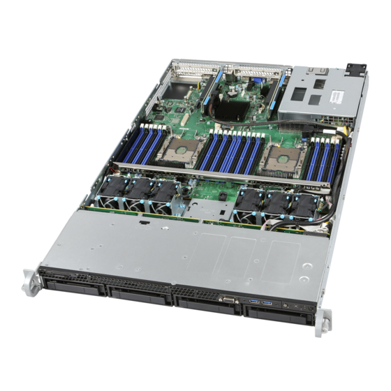
The Intel® Server Board S2600WF is a monolithic printed circuit board assembly with features that are intended for high density 1U and 2U rack mount servers. This server board is designed to support the Intel® Xeon® processor Scalable family. Previous generation Intel® Xeon® processors are not supported. -
Page 16: Figure 2. Intel® Server Board S2600Wf With Available Onboard Options
Support for dual hot swap power supply modules 80 mm M.2 1+0, 1+1, 2+0 configurations PCIe*/SATA 80 mm M.2 PCIe*/SATA Support for Intel® Integrated SAS RAID module options TPM 2.0 Figure 2. Intel® Server Board S2600WF with available onboard options... -
Page 17: Server Board Family Feature Set
Processor • (2) – LGA3647-0 (Socket P) processor sockets • Supports (1) or (2) processors from the Intel® Xeon® processor Scalable family (Platinum, Gold, Silver, and Bronze). Note: Previous generation Intel® Xeon® processors are not supported. • Maximum supported Thermal Design Power (TDP) of up to 205 W (board only) •... - Page 18 • Support for Intel® Server Management software • Dedicated onboard RJ45 management port • Advanced server management via Intel® RMM4 Lite – iPC AXXRMM4LITE2 (accessory option) Security • Trusted platform module 2.0 (Rest of World) – iPC AXXTPMENC8BPP (accessory option) •...
-
Page 19: Server Board Component/Feature Identification
Intel® Server Board S2600WF Product Family Technical Product Specification Server Board Component/Feature Identification Figure 3. Server board component/feature identification Note: Intel® Server Board S2600WFT shown. Some features may not be present on Intel® Server Boards S2600WF0 and/or S2600WFQ. -
Page 20: Figure 4. Intel® Server Board S2600Wf External I/O Connector Layout
– RJ45 serial A port – RJ45 network port – NIC #2 – Stacked 3-port USB 3.0 – Video – RJ45 dedicated management port Figure 4. Intel® Server Board S2600WF external I/O connector layout Figure 5. Intel® Light Guided Diagnostics - DIMM fault LEDs... -
Page 21: Figure 6. Intel® Light Guided Diagnostic - Led Identification
Intel® Server Board S2600WF Product Family Technical Product Specification Figure 6. Intel® Light Guided Diagnostic – LED identification Note: See Appendix B for POST Code Diagnostic LED decoder information. -
Page 22: Figure 7. Board Configuration And Recovery Jumpers
Intel® Server Board S2600WF Product Family Technical Product Specification Figure 7. Board configuration and recovery jumpers For more information on reset and recovery jumpers, see Section 11. -
Page 23: Server Board Mechanical Drawings
Intel® Server Board S2600WF Product Family Technical Product Specification Server Board Mechanical Drawings Figure 8. Intel® Server Board S2600WF primary side keepout zone... -
Page 24: Figure 9. Intel® Server Board S2600Wf Hole And Component Positions
Intel® Server Board S2600WF Product Family Technical Product Specification Figure 9. Intel® Server Board S2600WF hole and component positions... -
Page 25: Figure 10. Intel® Server Board S2600Wf Secondary Side Keepout Zone
Intel® Server Board S2600WF Product Family Technical Product Specification Figure 10. Intel® Server Board S2600WF secondary side keepout zone... -
Page 26: Figure 11. Intel® Server Board S2600Wf Primary Side Height Restrictions
Intel® Server Board S2600WF Product Family Technical Product Specification Figure 11. Intel® Server Board S2600WF primary side height restrictions... -
Page 27: Product Architecture Overview
Intel® Server Board S2600WF Product Family Technical Product Specification Product Architecture Overview The architecture of Intel® Server Board S2600WF product family is developed around the integrated features and functions of the Intel® Xeon® processor Scalable family, the Intel® C620 series chipset (PCH), Intel®... -
Page 28: System Software Stack
Figure 13. Intel® Server Board S2600WFQ architectural block diagram System Software Stack The server board includes a system software stack that consists of the bystem BIOS, BMC firmware, Intel® Management Engine (Intel® ME) firmware, and field replacement unit (FRU) and sensor data record (SDR) data. -
Page 29: Hot Keys Supported During Post
The FRUSDR utility is included in the SUP and OFU packages. For additional information, see Section 2.5.2. Refer to the following Intel documents for more indepth information about the system software stack and their functions: •... - Page 30 2.5.1.1 POST Logo/Diagnostic Screen If quiet boot is enabled in the BIOS setup utility, a splash screen is displayed with the standard Intel logo screen or a customized original equipment manufacturer (OEM) logo screen if one is present in the designated flash memory location.
-
Page 31: Field Replaceable Unit (Fru) And Sensor Data Record (Sdr) Data
SEL. From the UEFI shell, the BIOS can then be updated using a standard BIOS update procedure defined in update instructions provided with the system update package downloaded from the Intel website. Once the update has completed, switch the recovery jumper back to its default position and power cycle the system. - Page 32 Intel® Server Board S2600WF Product Family Technical Product Specification Note: The system may not operate with best performance or best/appropriate cooling if the proper FRU and SDR data is not installed. 2.5.2.1 Loading FRU and SDR Data The FRU and SDR data can be updated using a standalone FRUSDR utility in the UEFI shell, or can be done using the OFU utility program under a supported operating system.
-
Page 33: Processor Support
Intel® Server Board S2600WF Product Family Technical Product Specification Processor Support The server board includes two Socket-P LGA3647 processor sockets compatible with the Intel® Xeon® processor Scalable family (standard and fabric options) and supports processor thermal design power (TDP) of up to 205 W. -
Page 34: Figure 15. Processor Attached To The Processor Heat Sink Installation
Intel® Server Board S2600WF Product Family Technical Product Specification Figure 15. Processor attached to the processor heat sink installation Two bolster plate guide pins of different sizes allows the PHM to be installed only one way onto the processor socket assembly (see Figure 14). -
Page 35: Processor Thermal Design Power (Tdp) Support
The server board described in this document is designed to support the Intel® Xeon® processor Scalable family TDP guidelines up to and including 205 W. -
Page 36: Intel® Xeon® Processor Scalable Family Overview
Intel® Server Board S2600WF Product Family Technical Product Specification Intel® Xeon® Processor Scalable Family Overview The Intel® Server Board S2600WF product family supports for the Intel® Xeon® processor Scalable family: Intel® Xeon® Bronze XXXX processor • • Intel® Xeon® Silver XXXX processor Intel®... -
Page 37: Supported Technologies
3.3.1.2 Intel® Hyper-Threading Technology (Intel® HT Technology) The processor supports Intel® HT Technology, which allows an execution core to function as two logical processors. While some execution resources such as caches, execution units, and buses are shared, each logical processor has its own architectural state with its own set of general-purpose registers and control registers. - Page 38 Inlet air temperature monitoring – The Intel ME/Intel NM monitors server inlet air temperatures • periodically. If there is an alert threshold in effect, then Intel ME/Intel NM issues an alert when the inlet (room) temperature exceeds the specified value. The threshold value can be set by policy.
-
Page 39: Intel® Xeon® Processor Scalable Family With Integrated Intel® Omni-Path Fabric
Intel® AVX-512 - # of 512b FMA Units # of PCIe* Lanes The current fabric port count is one port per processor socket. Each Intel OP HFI port supports four lanes of 25 Gbps, providing 100 Gbps of bandwidth in a single direction. -
Page 40: Figure 18. Intel® Op Hfi Connector Location
IFT carrier board installed into in any available PCIe* add-in card slot or within the OCP module bay. A second cable carrying Intel Omni-Path side band signals is connected between the IFT carrier board and sideband connectors on the server board. External cables attach the IFT carrier board to an external Intel Omni-Path Switch. -
Page 41: Intel®Omni-Path Ift Carrier Accessory Kits
Intel® Server Board S2600WF Product Family Technical Product Specification Intel® Server S2600WF Intel® Server S2600WF Intel® Xeon® Dual Intel® Xeon® processor processor Scalable Scalable family with family Integrated Intel® OP HFI Internal Intel® OP HFI cable to QSFP Interface card Intel®... -
Page 42: Figure 21. Intel® Omni-Path Ift Carrier Accessory Kit Components
Intel® Server Board S2600WF Product Family Technical Product Specification Mezzanine IFT Carrier Card External QSFP28 PCIe* IFT Carrier Card Connectors Internal Omni-Path Sideband Internal Omni-Path IFT Card-to-CPU Fabric Procsessor Carrier x2 Figure 21. Intel® Omni-Path IFT Carrier Accessory Kit components The sideband cable connects the IFT carrier board to each fabric processor sideband connector on the server board. -
Page 43: Figure 23. Ift Carrier Board - Rear View
The server board has support for processor configurations where one or two installed processors may have an Intel OP HFI. In dual processor configurations, with at least one processor having support for Intel OP HFI, the following population rules apply: •... -
Page 44: Processor Population Rules
Note: The server board may support dual-processor configurations consisting of different processors that meet the defined criteria below; however, Intel does not perform validation testing of this configuration. In addition, Intel does not guarantee that a server system configured with unmatched processors will operate reliably. -
Page 45: Table 9. Mixed Processor Configurations Error Summary
• Takes fatal error action (see above) and does not boot until the fault condition is remedied If the link frequencies for all Intel® Ultra Path Interconnect (Intel® UPI) links can be adjusted to be the same: • Adjusts all Intel UPI interconnect link frequencies to highest common frequency. - Page 46 Intel® Server Board S2600WF Product Family Technical Product Specification Error Severity System Action when BIOS Detects the Error Condition • Logs the POST error code into the SEL. • Displays 816x: Processor 0x unable to apply microcode update message in the Processor error manager or on the screen.
-
Page 47: System Memory
Note: This generation server board supports DDR4 memory only. The Intel® Server Board S2600WF supports up to 24 DDR4 DIMMs, 12 per processor. Each installed processor supports six memory channels via two integrated memory controllers (IMC). On the server board, memory channels are assigned an identifier letter A through F, with each memory channel supporting two DIMM slots. -
Page 48: Supported Memory
DIMMs installed. On the Intel® Server Board S2600WF, a total of 24 DIMM slots are provided – 2 CPUs, 6 Memory Channels/CPU, 2 DIMMs/Channel. Figure 25 identifies all DIMM slots on the server board. - Page 49 Intel® Server Board S2600WF Product Family Technical Product Specification • Each installed processor provides six channels of memory. Memory channels from each processor are identified as Channels A – F. Each memory channel supports two DIMM slots, identified as slots 1 and 2.
-
Page 50: Dimm Population Guidelines For Best Performance
Intel® Server Board S2600WF Product Family Technical Product Specification 4.3.1 DIMM Population Guidelines for Best Performance Processors within the Intel Xeon processor Scalable family include two integrated memory controllers (IMC), each supporting three memory channels. Figure 26. DIMM population diagram... -
Page 51: Memory Ras Features
Memory RAS Features Supported memory RAS features are dependent on the level of processor installed. Each processor level within the Intel Xeon processor Scalable family has support for either standard or advanced memory RAS features as defined in Table 11. -
Page 52: Dimm Populations Rules And Bios Setup For Memory Ras
Intel® Server Board S2600WF Product Family Technical Product Specification 4.4.1 DIMM Populations Rules and BIOS Setup for Memory RAS Memory sparing and memory mirroring options are enabled in BIOS setup. • • Memory sparing and memory mirroring options are mutually exclusive. Only one operating mode may be selected in BIOS setup. -
Page 53: Pcie* Support
Intel® Server Board S2600WF Product Family Technical Product Specification PCIe* Support The PCI Express* (PCIe*) interface of the Intel® Server Board S2600WF product family is fully compliant with the PCIe Base Specification, Revision 3.0 supporting the following PCIe bit rates: Gen 3.0 (8.0 GT/s), Gen 2.0 (5.0 GT/s), and Gen 1.0 (2.5 GT/s). -
Page 54: Figure 27. Two Systems Connected Through An Ntb
Intel® Server Board S2600WF Product Family Technical Product Specification processor to independently configure and control the local system and provides isolation of the local host memory domain from the remote host memory domain, while enabling status and data exchange between the two domains. -
Page 55: System I/O
External I/O port support • Intel® QuickAssist Technology (Intel® QAT) Support This section provides a high level overview for Intel QAT and its support on the Intel® Server Board S2600WF product family. For more information about this technology, visit http://www.intel.com/content/www/us/en/embedded/technology/quickassist/overview.html. -
Page 56: Pcie* Add-In Card Support
When the PCH detects the link, it uses the additional x4 PCIe 3.0 uplink from each of the two OCuLink onboard connectors. Note: For Intel Server Board S2600WFQ, the Intel QAT cable is included with the board and is not available for sale separately. -
Page 57: Riser Slot #1 And Riser Slot #2 Riser Card Options
Intel® Server Board S2600WF Product Family Technical Product Specification PCIe* Add-in PCIe* Add-In Card PCIe* Add-in Card Card support Support Support Riser Slot #3 X12 PCIe* 3.0 Riser Slot #1 Riser Slot #2 x24 PCIe* 3.0 X24 PCIe* 3.0 X8 PCIe* CPU #2 X16 PCIe* –... -
Page 58: Figure 30. 1U One-Slot Pcie* Riser Card (Ipc - F1Ul16Riser3App)
Intel® Server Board S2600WF Product Family Technical Product Specification 6.2.1.1 1U One-Slot PCIe Riser Card (iPC – F1UL16RISER3APP) Each riser card assembly has support for a single full height, ½ length PCIe add-in card. However, riser card #2 may be limited to ½ length, ½ height add-in cards if either of the two mini-SAS HD connectors on the server board are used. -
Page 59: Riser Slot #3 Riser Card Option (Ipc - A2Ux8X4Riser)
PCIe x4 elec, x8 mechanical Slot-2 (bottom) PCIe x8 elec, x8 mechanical 6.2.3 Intel® Ethernet Network Adapter for OCP* Support The Intel Server Board S2600WF product family offers a line of LAN KR OCP mezzanine modules that follow the OCP 2.0 form factor. -
Page 60: Figure 34. Intel® Ethernet Network Adapter For Ocp* Connector
Quad Port, SFP+ X527DA4OCPG1P5 Dual Port, SFP+ (Intel® Server Board S2600WFT only) X527DA2OCPG1P5 Dual Port, 10Gb RJ45 (Intel Server Board S2600WFT only) X557T2OCPG1P5 Note: The dual-port SFP+ and dual-port 10 Gb RJ45+ modules are only supported on the Intel Server Board S2600WFT. -
Page 61: Intel® Integrated Raid Module Support
6.2.4 Intel® Integrated RAID Module Support The server board has support for many Intel and non-Intel PCIe add-in 12 Gb RAID adapters that can be installed in available PCIe add-in cards slots. For system configurations with limited add-in card slot availability, an optional Intel®... -
Page 62: Figure 36. M.2 Storage Device Connectors
Figure 36. M.2 storage device connectors Each M.2 connector can support PCIe or SATA modules that conform to a 2280 (80 mm) form factor. PCIe bus lanes for each connector are routed from the Intel chipset and can be supported in single processor configurations. -
Page 63: Onboard Pcie* Oculink Connectors
Figure 38. NVMe* storage bus event/error handling Intel VMD handles the physical management of NVMe storage devices as a standalone function but can be enhanced when Intel VROC support options are enabled to implement RAID based storage systems. - Page 64 For installed NVMe devices to utilize the Intel VMD features of the server board, Intel VMD must be enabled on the appropriate CPU PCIe root ports in BIOS setup. By default, Intel VMD support is disabled on all CPU PCIe root ports in BIOS setup.
-
Page 65: Figure 39. Intel® Vmd Support Disabled In Bios Setup
Intel® Server Board S2600WF Product Family Technical Product Specification Figure 39. Intel® VMD support disabled in BIOS setup Figure 40. Intel® VMD support enabled in BIOS setup... -
Page 66: Intel® Virtual Raid On Chip (Intel® Vroc) For Nvme
Graphical user interface (GUI) for Linux. • • 4K native NVMe SSD support. Enabling Intel VROC support requires installation of an optional upgrade key on to the server board as shown in Figure 42. Table 21 identifies available Intel VROC upgrade key options. -
Page 67: Onboard Sata Support
(2.5” SSD form factor only Enclosure LED management √ √ Note: Intel VROC upgrade keys referenced in Table 21 are used for PCIe NVMe SSDs only. For SATA RAID support, see Section 6.3.6. 6.3.5 Onboard SATA Support The server board utilizes two chipset embedded AHCI SATA controllers, identified as “SATA” and “sSATA”, providing for up to twelve 6 Gb/sec SATA ports. -
Page 68: Figure 43. Onboard Sata Port Connector Identification
Intel® Server Board S2600WF Product Family Technical Product Specification • Four ports from the mini-SAS HD (SFF-8643) connector labeled “SATA Ports 0-3” on the server board. Four ports from the mini-SAS HD (SFF-8643) connector labeled “SATA Ports 4-7” on the •... -
Page 69: Onboard Sata Raid Options
Staggered Disk Spin-Up Because of the high density of disk drives that can be attached to the Intel® C620 onboard AHCI SATA controller and the sSATA controller, the combined startup power demand surge for all drives at once can be much higher than the normal running power requirements and could require a much larger power supply for startup than for normal operations. -
Page 70: Figure 44. Bios Setup Mass Storage Controller Configuration Screen
Intel® Rapid Storage Technology Enterprise (Intel® RSTe) 5.0 for SATA Intel RSTe offers several options for RAID to meet the needs of the end user. AHCI support provides higher performance and alleviates disk bottlenecks by taking advantage of the independent DMA engines that each SATA port offers in the chipset. -
Page 71: Figure 45. Intel® Esrt2 Sata Raid-5 Upgrade Key (Ipn - Rksata4R5)
Intel® Embedded Server RAID Technology 2 (Intel® ESRT2) 1.60 for SATA Intel ESRT2 (powered by LSI*) is a driver-based RAID solution for SATA that is compatible with previous generation Intel® server RAID solutions. Intel ESRT2 provides RAID levels 0, 1, and 10, with an optional RAID 5 capability depending on whether a RAID upgrade key is installed. -
Page 72: Rear External Rj45 Connector Overview
The server board includes a dedicated 1 GbE RJ45 management port. The management port is active with or without the Intel® Remote Management Module 4 Lite Intel® RMM4 Lite) key installed. See Chapter 8 for additional information about onboard server management support. -
Page 73: Rj45 Network Interface Connectors (Intel® Server Board S2600Wft Only)
RJ45 Network Interface Connectors (Intel® Server Board S2600WFT only) The Intel Server Board S2600WFT provides two RJ45 networking ports, “NIC #1” and “NIC #2”, in addition to the RJ45 dedicated management port. The board includes the following onboard Intel® Ethernet Controller: •... -
Page 74: Figure 49. J4A2 Jumper Block For Serial-A Pin 7 Configuration
Intel® Server Board S2600WF Product Family Technical Product Specification Serial-A Pin 7 Config Jumper DSR: Pins 1-2 Pin 1 DCD: Pins 2-3 Figure 49. J4A2 Jumper block for Serial-A pin 7 configuration Serial B is provided through an internal DH-10 header labeled “Serial_B” on the server board. The connector location is shown in Figure 50 and the pinout is given in Table 26. -
Page 75: Usb Support
Intel® Server Board S2600WF Product Family Technical Product Specification USB Support USB support is provided through several onboard internal and external connectors as described in the following sections. 6.6.1 External USB 3.0 Connector The server board includes three (1x3 stacked) USB 3.0 ports on the back edge of the server board. -
Page 76: Front Panel Usb 2.0 Connector
Intel® Server Board S2600WF Product Family Technical Product Specification 2x port front panel USB 3.0 Figure 53. Front panel USB 3.0 connector Note: The following USB ports are routed to this connector: USB 3.0 ports 1 and 2; USB 2.0 ports 11 and 13. -
Page 77: Video Support
Intel® Server Board S2600WF Product Family Technical Product Specification 2x port front panel USB 2.0 connector Figure 54. Front panel USB 2.0 connector Table 28. Front panel USB 2.0 connector pinout ("FP_USB_2.0_5-6 ") Signal Name Pin# Pin# Signal Name P5V_USB_FP... -
Page 78: Onboard Video Connectors
Intel® Server Board S2600WF Product Family Technical Product Specification 2D Mode 2D Video Support (Color Bit) Resolution 8 bpp 16 bpp 24 bpp 32 bpp 1920 x 1200 Not Supported Not Supported 6.7.1 Onboard Video Connectors The server board includes two options to attach a monitor to the server system: •... -
Page 79: Onboard Video And Add-In Video Adapter Support
Intel® Server Board S2600WF Product Family Technical Product Specification V_BMC_GFX_FRONT_VSYN GROUND V_BMC_GFX_FRONT_HSYN V_BMC_FRONT_DDC_SDA_CONN V_FRONT_PRES_N V_BMC_FRONT_DDC_SCL_CONN P5V_VID_CONN_FNT 6.7.2 Onboard Video and Add-In Video Adapter Support Add-in video cards can be used to either replace or complement the onboard video option of the server board. -
Page 80: Onboard Connector/Header Pinout Definition
Intel® Server Board S2600WF Product Family Technical Product Specification Onboard Connector/Header Pinout Definition This section identifies the location and pinout for most onboard connectors and headers of the server board. Information for some connectors and headers are found elsewhere in the document where the feature is decribed in more detail. -
Page 81: Table 31. Main Power (Slot 1) Connector Pinout ("Main Pwr 1")
Intel® Server Board S2600WF Product Family Technical Product Specification Table 31. Main power (slot 1) connector pinout (“MAIN PWR 1”) Signal Name Pin # Pin# Signal Name GROUND GROUND GROUND GROUND GROUND GROUND GROUND GROUND GROUND GROUND GROUND GROUND GROUND... -
Page 82: Hot Swap Backplane Power Connector
Intel® Server Board S2600WF Product Family Technical Product Specification Signal Name Pin # Pin# Signal Name P12V P12V P12V P12V P3V3_AUX: PU_PS2FRU_A0 SMB_PMBUS_DATA_R P3V3_AUX: PD_PS2_FRU_A1 SMB_PMBUS_CLK_R P12V_STBY FM_PS_EN_PSU_N FM_PS_CR1 IRQ_SML1_PMBUS_ALERTR3_N P12V_SHARE ISENSE_P12V_SENSE_RTN TP_2_B24 ISENSE_P12V_SENSE FM_PS_COMPATIBILITY_BUS PWRGD_PS_PWROK 7.1.2 Hot Swap Backplane Power Connector The server board includes one white 2x6-pin power connector that when cabled provides power for hot swap backplanes, as shown in Figure 58. -
Page 83: Riser Card Supplemental 12-V Power Connectors
P12V GROUND Intel makes available a 12-V supplemental power cable that can support both 6- and 8-pin 12-V AUX power connectors found on high power add-in cards. The power cable (as shown in Figure 60) is available as a separate orderable accessory kit (iPC – AXXGPGPUCABLE). -
Page 84: Peripheral Power Connector
Intel® Server Board S2600WF Product Family Technical Product Specification Figure 60. High power add-in card 12-V auxiliary power cable option 7.1.4 Peripheral Power Connector The server board includes one 6-pin power connector intended to provide power for peripheral devices such as optical disk drives (ODDs) and/or solid state devices (SSDs). -
Page 85: Front Control Panel Headers And Connectors
Intel® Server Board S2600WF Product Family Technical Product Specification Front Control Panel Headers and Connectors The server board includes several connectors that provide various possible front panel options. This section provides a functional description and pinout for each connector. For front panel control button and LED support, the server board includes two connector options: a 30-pin SSI compatible front panel header labeled “FRONT_PANEL”, and a custom high density 30-pin front panel... -
Page 86: Front Panel Led And Control Button Features Overview
Intel® Server Board S2600WF Product Family Technical Product Specification The pinout for both connector types, shown in Table 37, is identical. Table 37. 30-pin front panel connector pinouts Signal Name Pin# Pin# Signal Name P3V3_AUX P3V3_AUX P5V_STBY FP_PWR_LED_BUF_R_N FP_ID_LED_BUF_R_N P3V3... -
Page 87: Table 39. Nmi Signal Generation And Event Logging
Intel® Server Board S2600WF Product Family Technical Product Specification The following actions cause the BMC to generate an NMI pulse: Receiving a Chassis Control command to pulse the diagnostic interrupt. This command does not cause an event to be logged in the SEL. -
Page 88: System Fan Connectors
Intel® Server Board S2600WF Product Family Technical Product Specification System Fan Connectors The server board is capable of supporting up to a total of six system fans. Each system fan includes a pair of fan connectors: a 1x10 pin connector to support a dual rotor cabled fan, typically used in 1U system configurations;... -
Page 89: Management Connectors
Intel® Server Board S2600WF Product Family Technical Product Specification Figure 66. Fan connector locations Management Connectors The server board includes several management interface connectors. Table 42, Table 43, and Table 44 provide the pinout definition for each. 3-pin HSBP I2C (J5C3) -
Page 90: Table 43. Hot Swap Backplane I 2 C Connector - Smbus 4-Pin (J1K1)
Intel® Server Board S2600WF Product Family Technical Product Specification Table 43. Hot swap backplane I C connector – SMBUS 4-pin (J1K1) Signal Ground RST_PCIE_SSD_PERST Table 44. IPMB – SMBUS 4-pin (J1C3) Signal CMOS_SDA Ground CMOS_SCL P5V_AUX... -
Page 91: Basic And Advanced Server Management Features
Intel® RMM4 Lite Key Figure 68. Intel® RMM4 Lite activation key installation When the BMC firmware initializes, it attempts to access the Intel RMM4 Lite. If the attempt to access the Intel RMM4 Lite is successful, then the BMC activates the advanced features. -
Page 92: Dedicated Management Port
Intel® Server Board S2600WF Product Family Technical Product Specification Advanced w/ Intel® RMM4 Feature Basic Lite Key ARP/DHCP support PECI thermal management support E-mail alerting Embedded web server SSH support Integrated KVM Integrated remote media redirection Lightweight Directory Access Protocol (LDAP) Intel®... - Page 93 Provide the ability to customize the port numbers used for SMASH, http, https, KVM, secure KVM, re- • mote media, and secure remote media. For additional information, refer to the Intel® Remote Management Module 4 and Integrated BMC Web Console User Guide.
-
Page 94: Advanced Management Feature Support
The BMC firmware supports keyboard, video, and mouse redirection (KVM) over LAN. This feature is available remotely from the embedded web server as a Java* applet. This feature is only enabled when the Intel® RMM4 Lite is present. The client system must have a Java Runtime Environment (JRE) version 6.0 or later to run the KVM or media redirection applets. -
Page 95: Media Redirection
Intel® Server Board S2600WF Product Family Technical Product Specification • 1280x1024 at 60 Hz • 1440x900 at 60 Hz 1600x1200 at 60 Hz • 8.3.1.1 Availability The remote KVM session is available even when the server is powered off (in stand-by mode). No restart of the remote KVM session is required during a server reset or power on/off. -
Page 96: Remote Console
Network Address Translation (NAT) settings have to be configured accordingly. For additional information, reference the Intel® Remote Management Module 4 and Integrated BMC Web Console User Guide. -
Page 97: Light Guided Diagnostics
Intel® Server Board S2600WF Product Family Technical Product Specification Light Guided Diagnostics The server board includes several onboard LED indicators to aid troubleshooting various board level faults. Figure 70 and Figure 71 show the location for each LED. Figure 70. Onboard diagnostic and fault LED placement... -
Page 98: System Id Led
Intel® Server Board S2600WF Product Family Technical Product Specification Figure 71.DIMM fault LED placement System ID LED The server board includes a blue system ID LED which is used to visually identify a specific server installed among many other similar servers. There are two options available for illuminating the System ID LED. -
Page 99: Bmc Boot/Reset Status Led Indicators
Intel® Server Board S2600WF Product Family Technical Product Specification Table 47. System status LED states State System Status Description Solid green Indicates that the system status is ‘healthy’. The system is not exhibiting any errors. AC power is present and BMC has booted and manageability functionality is up and running. -
Page 100: Post Code Diagnostic Leds
Intel® Server Board S2600WF Product Family Technical Product Specification Both universal bootloader 6 Hz blinking Non-recoverable condition. Contact an Intel representative for Solid amber (u-Boot) images bad blue information on replacing this motherboard. Blinking green indicates degraded state (no manageability), blinking... -
Page 101: 10. System Security
Intel® Server Board S2600WF Product Family Technical Product Specification 10. System Security The server board supports a variety of system security options designed to prevent unauthorized system access or tampering of server settings. System security options supported include: Password protection •... -
Page 102: System Administrator Password Rights
Intel® Server Board S2600WF Product Family Technical Product Specification re-ordering, and prevent unauthorized system power on. It is strongly recommended that an administrator password be set. A system with no administrator password set allows anyone who has access to the server to change BIOS settings. -
Page 103: 10.2 Front Panel Lockout
Intel® Server Board S2600WF Product Family Technical Product Specification administrator password to function, and the USB reordering is suppressed as long as the administrator password is enabled. Users are restricted from booting in anything other than the boot order defined in setup by an administrator. -
Page 104: Physical Presence
In addition, Intel TXT requires the system to include a TPM v1.2, as defined by the Trusted Computing Group TPM PC Client Specifications, Revision 1.2. When available, Intel TXT can be enabled or disabled in the processor by a BIOS setup option. For general information about Intel TXT, visit http://www.intel.com/technology/security/. -
Page 105: 11. Reset And Recovery Jumpers
Intel® Server Board S2600WF Product Family Technical Product Specification 11. Reset and Recovery Jumpers The server board includes several jumper blocks which can be used to configure, protect, or recover specific features of the server board. Figure 73 identifies the location of each jumper block on the server board. Pin 1 of each jumper block can be identified by the arrowhead (▼) silkscreened on the server board next to the... -
Page 106: 11.2 Password Clear Jumper Block
11.3 Intel® Management Engine (Intel® ME) Firmware Force Update Jumper Block When the Intel ME firmware force update jumper is moved from its default position, the Intel ME is forced to operate in a reduced minimal operating capacity. This jumper should only be used if the Intel ME firmware has gotten corrupted and requires re-installation. -
Page 107: 11.4 Bmc Force Update Jumper Block
BMC to abort its normal boot process and stay in the boot loader without executing any Linux* code. This jumper should only be used if the BMC firmware has become corrupted and requires re-installation. Note: System update files are included in the SUP posted to Intel’s download center website at http://downloadcenter.intel.com. - Page 108 This jumper is not used when the BIOS is operating normally to update the BIOS from one version to another. Note: System update files are included in the SUP posted to Intel’s download center website at http://downloadcenter.intel.com. To use the BIOS recovery jumper, perform the following steps: 1.
-
Page 109: 12. Platform Management
The Intel® Server System BMC Firmware External Product Specification (EPS) and the Intel® Server System BIOS External Product Specification (EPS) for Intel® Server Products based on the Intel® Xeon® processor E5- 2600 v5 product families should be referenced for more in-depth and design level platform management information. - Page 110 Intel® Server Board S2600WF Product Family Technical Product Specification • Fault resilient booting (FRB) including FRB-2 supported by the watchdog timer functionality. • Chassis intrusion detection (dependent on platform support). Fan speed control with SDR, fan redundancy monitoring, and support.
-
Page 111: 12.2 Platform Management Features And Functions
Intel® Server Board S2600WF Product Family Technical Product Specification • ENERGY STAR* server support. • Smart ride through (SmaRT) / closed-loop system throttling (CLST). Power supply cold redundancy. • • Power supply firmware update. Power supply compatibility check. • BMC firmware reliability enhancements: •... -
Page 112: System Initialization
The BMC reads these from the CPU through PECI Proxy mechanism provided by Intel® ME. The BMC uses these values as part of the fan-speed-control algorithm. -
Page 113: 12.3 Sensor Monitoring
IPMI watchdog sensor BMC watchdog sensor • BMC system management health monitoring • VR watchdog timer • System airflow monitoring sensors - valid for Intel® server chassis only • • Fan monitoring sensors Thermal monitoring sensors • Voltage monitoring sensors •... -
Page 114: Standard Fan Management
Intel® Server Board S2600WF Product Family Technical Product Specification For analog/threshold sensors, with the exception of processor temperature sensors, critical and non-critical thresholds (upper and lower) are set through SDRs and event generation enabled for both assertion and de- assertion events. - Page 115 Intel® Server Board S2600WF Product Family Technical Product Specification is still present, the boost state returns once the sensor has re-initialized and the threshold violation is detected again. 12.3.3.2 Fan Redundancy Detection The BMC supports redundant fan monitoring and implements a fan redundancy sensor. A fan redundancy sensor generates events when its associated set of fans transitions between redundant and non-redundant states, as determined by the number and health of the fans.
-
Page 116: Memory Thermal Management
Intel® Server Board S2600WF Product Family Technical Product Specification • BMC temperature sensor 3, 6 • Global aggregate thermal margin sensors Hot swap backplane temperature sensors • • Intel® OCP module temperature sensor (with option installed) Intel® SAS module (with option installed) •... -
Page 117: Power Management Bus (Pmbus*)
CLTT, for which the integrated memory controller estimates the DRAM temperature in between actual reads of the TSODs. Hybrid CLTT is used on all Intel Server Systems supporting the Intel Xeon processor Scalable family that have DIMMs with thermal sensors. Therefore, the terms Dynamic-CLTT and Static-CLTT are really referring to this “hybrid”... -
Page 118: Component Fault Led Control
Fault LED. These LEDs are only active when the system is in the ‘on’ state. The BMC does not activate or change the state of the LEDs unless instructed by the BIOS. HDD status LEDs – The HSBP PSoC* of supported Intel and non-Intel chassis owns the hardware con- •... -
Page 119: Appendix A. Integration And Usage Tips
This server board supports the Intel® Xeon® processor Scalable family with a Thermal Design Power (TDP) of up to and including 205 Watts. Previous generations of the Intel® Xeon® processors are not supported. Server systems using this server board may or may not meet the TDP design limits of the server board. -
Page 120: Appendix B. Post Code Diagnostic Led Decoder
Intel® Server Board S2600WF Product Family Technical Product Specification Appendix B. POST Code Diagnostic LED Decoder As an aid in troubleshooting a system hang that occurs during a system POST process, the server board includes a bank of eight POST code diagnostic LEDs on the back edge of the server board. -
Page 121: B.1. Early Post Memory Initialization Mrc Diagnostic Codes
Intel® Server Board S2600WF Product Family Technical Product Specification B.1. Early POST Memory Initialization MRC Diagnostic Codes Memory initialization at the beginning of POST includes multiple functions: discovery, channel training, validation that the DIMM population is acceptable and functional, initialization of the IMC and other hardware settings, and initialization of applicable RAS configurations. -
Page 122: Table 54. Mrc Fatal Error Codes
Intel® Server Board S2600WF Product Family Technical Product Specification Table 54. MRC fatal error codes Upper Nibble Lower Nibble Post Code (Hex) Description No usable memory error 01h = No memory was detected from SPD read, or invalid config that causes no operable memory. -
Page 123: B.2. Bios Post Progress Codes
Intel® Server Board S2600WF Product Family Technical Product Specification B.2. BIOS POST Progress Codes Table 55 provides a list of all POST progress codes. Table 55. POST progress codes Upper Nibble Lower Nibble Post Code (Hex) Description SEC Phase First POST code after CPU reset... - Page 124 Intel® Server Board S2600WF Product Family Technical Product Specification Upper Nibble Lower Nibble Post Code (Hex) Description DXE Removable Media Detect DXE Removable Media Detected DXE BDS started DXE BDS connect drivers DXE PCI bus begin DXE PCI Bus HPC Init...
- Page 125 Intel® Server Board S2600WF Product Family Technical Product Specification Upper Nibble Lower Nibble Post Code (Hex) Description S3 Resume S3 Resume PEIM (S3 started) S3 Resume PEIM (S3 boot script) S3 Resume PEIM (S3 Video Repost) S3 Resume PEIM (S3 OS wake)
-
Page 126: Appendix C. Post Code Errors
Pause” option setting in the BIOS setup does not have any effect on this error. Note: The POST error codes in the following table are common to all current generation Intel® server platforms. Features present on a given server board/system determine which of the listed error codes are... -
Page 127: Table 56. Post Error Messages And Handling
Intel® Server Board S2600WF Product Family Technical Product Specification Table 56. POST error messages and handling Error Code Error Message Action message Response 0012 System RTC date/time not set Major 0048 Password check failed Please put right password. Major 0140... - Page 128 Intel® Server Board S2600WF Product Family Technical Product Specification Error Code Error Message Action message Response Memory component could not be configured in the 85FC Major selected RAS mode 8501 Memory Population Error Please plug DIMM at right population. Major...
- Page 129 Intel® Server Board S2600WF Product Family Technical Product Specification Error Code Error Message Action message Response 8544 Memory disabled.CPU1_DIMM_B2 please remove the disabled DIMM. Major 8545 Memory disabled.CPU1_DIMM_B3 please remove the disabled DIMM. Major 8546 Memory disabled.CPU1_DIMM_C1 please remove the disabled DIMM.
- Page 130 Intel® Server Board S2600WF Product Family Technical Product Specification Error Code Error Message Action message Response 8566 Memory encountered a Serial Presence Detection(SPD) Major failure.CPU1_DIMM_C1 8567 Memory encountered a Serial Presence Detection (SPD) Major failure.CPU1_DIMM_C2 8568 Memory encountered a Serial Presence Detection (SPD) Major failure.CPU1_DIMM_C3...
- Page 131 Intel® Server Board S2600WF Product Family Technical Product Specification Error Code Error Message Action message Response 85C0 Memory failed test/initialization CPU2_DIMM_C3 please remove the disabled DIMM. Major 85C1 Memory failed test/initialization CPU2_DIMM_D1 please remove the disabled DIMM. Major 85C2 Memory failed test/initialization CPU2_DIMM_D2 please remove the disabled DIMM.
- Page 132 Intel® Server Board S2600WF Product Family Technical Product Specification Error Code Error Message Action message Response 85E4 Memory encountered a Serial Presence Detection(SPD) Major failure.CPU2_DIMM_E1 85E5 Memory encountered a Serial Presence Detection(SPD) Major failure.CPU2_DIMM_E2 85E6 Memory encountered a Serial Presence Detection(SPD) Major failure.CPU2_DIMM_E3...
-
Page 133: C.1. Post Error Beep Codes
Codes that are common across all Intel server boards and systems that use same generation chipset are listed in Table 58. Each digit in the code is represented by a sequence of beeps whose count is equal to the digit. -
Page 134: Appendix D. Statement Of Volatile Memory Components
Intel® Server Board S2600WF Product Family Technical Product Specification Appendix D. Statement of Volatile Memory Components This section is used to identify the volatile and non-volatile memory components of the Intel® Server Board S2600WF product family. Table 59 provides the following data for each identified component. -
Page 135: Table 59. Volatile And Non-Volatile Components
Intel® Server Board S2600WF Product Family Technical Product Specification Table 59. Volatile and non-volatile components Component Type Size Board Location User Data Name Non-volatile 64 MB U3D1 No(BIOS) BIOS Flash Non-volatile 64 MB U1D1 NO(FW) BMC Flash Non-Volatile 4 Mbit... -
Page 136: Appendix E. Supported Intel® Server Systems
Appendix E. Supported Intel® Server Systems The Intel® Server Board S2600WF product family is designed to be integrated into high density 1U and 2U rack mount servers chassis. Intel® Server Systems in this server board family include the Intel Server System R1000WF product family and the Intel Server System R2000WF product family. -
Page 137: Table 60. Intel® Server System R1000Wf Product Family Feature Set
Intel® Server Board S2600WF Product Family Technical Product Specification Table 60. Intel® Server System R1000WF product family feature set Feature Description Chassis Type 1U rack mount chassis Server Board Intel® Server Board S2600WF product family Maximum Supported Processor Up to 165 Watts... -
Page 138: E.2. Intel® Server System R2000Wf Product Family
Intel® Server Board S2600WF product family Maximum Supported Processor • Up to 140 W for all Intel® system configuration options. Thermal Design Power (TDP) • 165 W processors supported on Intel® Server Chassis R2208WFxxxx and R2308WFxxxx configurations only. External I/O Connections • DB-15 video connectors o Front and back (non-storage system configurations only) •... - Page 139 Intel® Server Board S2600WF Product Family Technical Product Specification Feature Description Riser Card Support Support for three riser cards: • Riser #1 – PCIe* 3.0 x24 - up to 3 PCIe slots • Riser #2 – PCIe* 3.0 x24 - up to 3 PCIe slots •...
-
Page 140: Appendix F. Glossary
Intel® Server Board S2600WF Product Family Technical Product Specification Appendix F. Glossary Term Definition Baseboard Management Controller BIOS Basic Input/Output System CMOS Complementary Metal-oxide-semiconductor Central Processing Unit DDR4 Double Data Rate 4th edition DIMM Dual In-line Memory Module DIMMs per Channel...
Need help?
Do you have a question about the S2600WF and is the answer not in the manual?
Questions and answers