Table of Contents
Advertisement
Advertisement
Chapters
Table of Contents

Related Manuals for Beechcraft Baron G58


Summary of Contents for Beechcraft Baron G58
- Page 2 Any Raytheon marks contained in this document are owned by Raytheon Company and are employed pursuant to a limited license granted by Raytheon Company. Prior to March 26, 2007, Beechcraft Corporation was owned by Raytheon Company but is no longer affiliated wtih Raytheon Company.
- Page 3 LIST OF EFFECTIVE PAGES This listing contains all current pages with effective revision number or date. It should be used after posting changes to ensure the manual is complete and up-to-date. Always destroy superseded pages when you insert revised pages. Model G58 Baron ®...
- Page 4 List Of Effective Pages (Cont’d) P/N 58-590000-67 Revision A12 - May, 2015 3A-1 thru 3A-9 ..... . . April, 2008 3A-10 .
- Page 5 LOG OF TEMPORARY CHANGES Model G58 Baron Pilot’s Operating Handbook FAA Approved Airplane Flight Manual P/N 58-590000-67 June, 2011 Temporary Changes to this manual must be in the airplane for all flight operations. PART NUMBER SUBJECT DATE 58-590000-67TC1 Uncommanded pulsing of the June, Rev 1 control column during overly...
- Page 6 Log Of Temporary Changes (Cont’d) P/N 58-590000-67 Revised June, 2011 PART NUMBER SUBJECT DATE 58-590000-67TC5 Incorporated into the 58-590000- Incorpo- 67A8 revision. Please discard all rated 58-590000-67TC5 pages: 1 of 4 thru 4 of 4. NOTE: This page should be filed in the front of the manual immediately in front of the Log Of Revisions page(s).
- Page 7 Section 3A Abnormal Procedures Model G58 Baron Temporary Change to the Pilot’s Operating Handbook FAA Approved Airplane Flight Manual P/N 58-590000-67TC1 Rev 1 Publication Model G58 Pilot’s Operating Handbook and Affected FAA Approved Airplane Flight Manual (58- 590000-67, Issued November, 2005) Airplane Serials TH-2125 thru TH-2158 not in compliance Numbers...
- Page 8 Model G58 Baron Temporary Change to the Pilot’s Operating Handbook FAA Approved Airplane Flight Manual P/N 58-590000-67TC2 Publication Model G58 Pilot’s Operating Handbook Affected and FAA Approved Airplane Flight Manual 58-590000-67, Issued November, 2005. Airplane Serial TH-2138, TH-2141 and after and prior Numbers Affected airplanes in compliance with Service Bulletin...
-
Page 10: Revision A12 - May
Revised AIRPLANE THREE-VIEW. 1-12 and 1-13 Revised PROPELLER MANUFACTURER and PROPELLER TYPE. Added PITCH SETTINGS and PROPELLER DIAMETER. Shifted data. Section 2 Reformatted to change Hawker Beechcraft Cor- poration to Beechcraft Corporation. 2-1 thru 2-4 Revised Table of Contents. 1 of 2... - Page 11 Revised PROPELLER MANUFACTURER, PRO- PELLER TYPE and PROPELLER DIAMETER. Shifted data. 2-18 Revised website reference. Section 7 Reformatted to change Hawker Beechcraft Corporation to Beechcraft Corporation. 7-1 thru 7-6 Revised Table of Contents. 7-31 Revised PROPELLERS. Shifted data. 2 of 2...
- Page 12 Revision A11 - July, 2014 PAGE DESCRIPTION Title Page LOEP Section 5 Reformatted to change Hawker Beechcraft Cor- poration to Beechcraft Corporation. 5-24 Added note to Manifold Pressure vs RPM graph - CONTINUOUS OPERATION AT PEAK EGT IS PERMITTED. 1 of 1...
- Page 13 LOG OF REVISIONS Model G58 Baron ® (Serials TH-2125 and After) Pilot’s Operating Handbook FAA Approved Airplane Flight Manual P/N 58-590000-67 Revision A10 - August, 2013 PAGE DESCRIPTION Title Page LOEP Section 4 4-22 Revised Step 4. of CRUISE procedure to refer- ence Leaning Using EGT Indication in Other Nor- mal Procedures.
- Page 14 LOG OF REVISIONS Model G58 Baron ® (Serials TH-2125 and After) Pilot’s Operating Handbook FAA Approved Airplane Flight Manual P/N 58-590000-67 Revision A9 - April, 2012 PAGE DESCRIPTION Title Page LOEP Section 1 1-18 Revised definition of OAT. Section 4 4-30 Revised Step 3.
- Page 15 Log Of Revisions (Cont’d) P/N 58-590000-67 Revision A9 - April, 2012 PAGE DESCRIPTION 5-36 thru 5-39 Revised 2300 and 2500 rpm Cruise Power Set- tings tables to replace IOAT values with OAT val- ues. Removed 2100 rpm Cruise Power Settings tables.
- Page 16 LOG OF REVISIONS Model G58 Baron ® (Serials TH-2125 and After) Pilot’s Operating Handbook FAA Approved Airplane Flight Manual P/N 58-590000-67 Revision A8 - June, 2011 PAGE DESCRIPTION Title Page LOEP LOTC Section 1 1-13 Incorporated 58-590000-67TC4 (Chinese Avia- tion Gasoline). 1-23 Changed Generic to Generic:.
- Page 17 Log Of Revisions (Cont’d) P/N 58-590000-67 Revision A8 - June, 2011 PAGE DESCRIPTION 2-23 Changed Versions to Version. Changed ‘and’ to ‘or’. 2-25 and 2-26 Added Item 9. Renumbered remaining items. Shifted data. 2-27 Shifted data. Section 3A 3A-19 Changed FAILURE OF REMOTE AUTONO- MOUS INTEGRITY MONITORING (RAIM) to LOSS OF RECEIVER AUTONOMOUS INTEG- RITY MONITORING (RAIM).
- Page 18 Log Of Revisions (Cont’d) P/N 58-590000-67 Revision A8 - June, 2011 PAGE DESCRIPTION 7-50 thru 7-53 Shifted data. 7-69 Changed Versions to Version. Changed ‘and’ to ‘or’. 7-74 Changed ‘and’ to ‘or’. 7-80 Changed ‘and’ to ‘or’. Removed ‘precision’. Added ‘approach with’. 7-83 Changed Versions to Version.
- Page 19 Revised Propeller Manufacturer. Added supple- ment AFMS 20002-1. Removed Pitch Settings and Propeller Diameter. 2-22 Changed FM to FPM and 45°30’30’ to 45°30’30”. Section 5 - Changed Raytheon Aircraft Company to Hawker Beechcraft Corporation. Revised Table of Contents. 1 of 2...
- Page 20 DESCRIPTION 5-23 Corrected spelling of angle. 5-45 Changed 196 to 190. Section 6 - Changed Raytheon Aircraft Company to Hawker Beechcraft Corporation. Corrected Table of Contents. 7-31 Revised Propellers. Added supplement AFMS 20002-1. 7-49 Changed V to VDC (2 places).
- Page 21 LOG OF REVISIONS Model G58 Baron ® (Serials TH-2125 and After) Pilot’s Operating Handbook FAA Approved Airplane Flight Manual P/N 58-590000-67 Revision A6 - February, 2009 PAGE DESCRIPTION Title Page LOEP Revised Table of Contents. 2-16 Added Software Version 0857.06. 2-17 Added Software Version 0857.06.
- Page 22 Log Of Revisions (Cont’d) P/N 58-590000-67 Revision A6 - February, 2009 PAGE DESCRIPTION 2-27 Changed “hanger” to “hangar” and shifted data. 2-28 Changed “data base” to “database” in three places and shifted data. 2-29 thru 2-41 Shifted data. 2-42 Added Magnetic Compass to the Kinds of Operations Equipment List and shifted data.
- Page 23 3A-13 thru 3A-17 Inserted “Cabin Heater” and “Wing Ice Light” procedures. Shifted data. 4-3 and 4-4 Inserted “Cabin Heater” procedure and updated RAC to Hawker Beechcraft. 4-10 Inserted “Cabin Heater Over-Tempera- ture Switch,” “Heater Exhaust Outlet” & “Heater Fuel Drain Line” Procedures.
- Page 24 LOG OF REVISIONS Model G58 Baron (Serials TH-2125 and After) Pilot’s Operating Handbook FAA Approved Airplane Flight Manual P/N 58-590000-67 Revision A4 - April, 2008 PAGE DESCRIPTION Title Page LOEP 1-1 and 1-2 Revised Table of Contents and Reformatted 1-3 thru 1-22 Revised “Introduction”, “Important Notice”, “Revi- sion Service”, “Supplements”, “Engine Controls and Instrument Terminology”...
- Page 25 Log Of Revisions (Cont’d) P/N 58-590000-67 Revision A4 - April, 2008 PAGE DESCRIPTION 3-3 thru 3-14 Reformatted 3-15 and 3-16 Revised “Autopilot Automatic Disengagement”, “Autopilot Overspeed Recovery [MAXSPD]” and Reformatted 3-17 thru 3-19 Revised “Electric Pitch Trim Failure [PTRM]”, “Unscheduled Electric Pitch Trim” and Reformat- 3-20 thru 3-23 Revised “Garmin Terrain Awareness and Warning System (TAWS)”...
- Page 26 Log Of Revisions (Cont’d) P/N 58-590000-67 Revision A4 - April, 2008 PAGE DESCRIPTION 4-18 thru 4-21 Revised “Before Takeoff (Runup)”, Shifted Data and Reformatted 4-22 thru 4-28 Revised “Cruise”, Shifted Data and Reformatted 4-29 thru 4-32 Revised “Leaning Using The Lean Assist Page”, “Monitoring Engine Systems (Oil, Fuel, Electri- cal)”, “Monitoring The CHTs and EGTs”, Shifted Data and Reformatted...
- Page 27 Log Of Revisions (Cont’d) P/N 58-590000-67 Revision A4 - April, 2008 PAGE DESCRIPTION 8-5 thru 8-18 Revised “Introduction to Servicing”, “Pub- lications”, “Airplane Inspection Periods”, “Alterations or Repairs to the Airplane”, “Fuel Cells” and Reformatted 8-19 thru 8-34 Revised “Batteries”, “Tires”, “Brakes”, “Heating and Ventilating System”, “Alternators”, “Exterior Painted Surfaces”, “Magnetos”, “Consumable Materials”, “Lamp Replacement Guide”...
- Page 28 LOG OF REVISIONS Model G58 Baron (Serials TH-2125 and After) Pilot’s Operating Handbook FAA Approved Airplane Flight Manual P/N 58-590000-67 Revision A3 - March, 2007 PAGE DESCRIPTION Title Page Revised for Company Name Change Logo Page Revised for Company Name Change LOEP Revised for Company Name Change Revised for Company Name Change...
- Page 29 LOG OF REVISIONS Model G58 Baron (Serials TH-2125 and After) Pilot’s Operating Handbook FAA Approved Airplane Flight Manual P/N 58-590000-67 Revision A2 - January, 2007 PAGE DESCRIPTION Title Page LOEP Revised “Important Notice” 1-12 Revised “Propeller Manufacturer” 1-19 Revised “Engine Controls and Instruments Termi- nology”...
- Page 30 (Cont’d) PAGE DESCRIPTION 3-19 Revised “Attitude and Heading Reference System (AHRS) Failure” 3A-1 and 3A-2 Revised Table of Contents 3A-5 Revised “Starter Engage [L START ENGD] or [R START ENGD]” 3A-14 Revised “Autopilot Failures” 3A-23 Revised Heading and “Altimeter Disagreement” 4-8 and 4-9 Revised “Preflight Inspection”...
- Page 31 (Cont’d) PAGE DESCRIPTION 7-33 thru 7-38 Added “Fuel Drain” and Shifted Data 7-39 thru 7-42 Revised “Fuel Off-Loading”, “Protective Devices”, “Distribution” and Shifted Data 7-43 Revised Illustration and Shifted Data 7-44 thru 7-48 Revised Tables and Shifted Data 7-49 and 7-50 Revised Table, “External Power”...
-
Page 32: Revision A12
LOG OF REVISIONS Model G58 Baron (Serials TH-2125 and After) Pilot’s Operating Handbook FAA Approved Airplane Flight Manual P/N 58-590000-67 Revision A1 - February, 2006 PAGE DESCRIPTION Title Page LOEP 1-23 Revised “Acronyms” 2-1 thru 2-4 Revised Table of Contents 2-12 Revised “Weight Limit”... - Page 33 (Cont’d) PAGE DESCRIPTION 3A-19 thru 3A-24 Added “Garmin Terrain Awareness and Warning System (TAWS)” and Shifted Data 4-1 thru 4-4 Revised Table of Contents 4-5 and 4-6 Reprint - No Change Revised “Preflight Inspection” 4-8 thru 4-10 Reprint - No Change 4-11 Revised “Preflight Inspection”...
- Page 34 (Cont’d) PAGE DESCRIPTION Revised “Subpanel” and “Pedestal” 7-10 thru 7-14 Reprint - No Change 7-15 Revised “Ground Control” and “Wing Flaps” 7-16 Reprint - No Change 7-17 and 7-18 Revised “Position Lights”, “Safety Switch”, “Warn- ing Horn and [GEAR UP] Annunciation” and “Man- ual Extension”...
- Page 35 (Cont’d) PAGE DESCRIPTION 7-40 and 7-41 Revised “Distribution” Shifted Data 7-42 Revised Illustration and Shifted Data 7-43 thru 7-46 Revised Tables and Shifted Data 7-47 Revised “Monitoring the Electrical System” and Shifted Data 7-48 Revised Table and Shifted Data 7-49 Revised “Starters”, “External Power”...
- Page 36 LOG OF REVISIONS Model G58 Baron (Serials TH-2125 and After) Pilot’s Operating Handbook FAA Approved Airplane Flight Manual P/N 58-590000-67 Original Issue - November, 2005 PAGE DESCRIPTION Title Page LOEP L OR 1-1 thru 1-24 2-1 thru 2-38 3-1 thru 3-24 3A-1 thru 3A-20 4-1 thru 4-52 5-1 thru 5-58...
-
Page 37: Table Of Contents
Model G58 SECTION 1 GENERAL TABLE OF CONTENTS SUBJECT PAGE Introduction ........1-3 Important Notice . - Page 38 Model G58 SECTION 1 GENERAL TABLE OF CONTENTS (CONT’D) SUBJECT PAGE Fuel ........1-14 Approved Engine Fuels .
-
Page 39: Introduction
Attention is called to Section 10, SAFETY INFORMATION. Beechcraft Corporation feels that it is highly important to have Safety Information in condensed form in the hands of the pilots. The Safety Information should be read and studied. -
Page 40: Important Notice
Section 1 General Model G58 Salvaged airplane parts, reworked parts obtained from non-Beechcraft Corporation approved sources, or parts, components, or structural assemblies, the service history of which is unknown or cannot be authenti- cated, may have been subjected to unac-... -
Page 41: Use Of The Handbook
Beechcraft Corporation Authorized Outlets can provide recom- mended modification, service, and operating procedures issued by both the FAA and Beechcraft Corporation, which are designed to get maximum utility and safety from the airplane. USE OF THE HANDBOOK WARNINGS, CAUTIONS, AND NOTES... -
Page 42: Revising The Handbook
Section 1 General Model G58 Operating procedures, techniques, etc., which could result in damage to equipment if not carefully followed. NOTE An operating procedure, technique, etc., which is considered essential to empha- size. REVISING THE HANDBOOK The Pilot’s Operating Handbook is designed to facilitate main- taining the documents necessary for the safe and efficient operation of the airplane. -
Page 43: Revision Service
FAA Approved Airplane Flight Manual. 2. Original issues and revisions of FAA Approved Airplane Flight Manual Supplements. 3. Original issues and revisions of Beechcraft Corporation Service Bulletins. The above publications will be provided only to the registered owner/operator at the address listed on the FAA Aircraft Regis- tration Branch List or the Beechcraft Corporation Domestic/ International Owner’s Notification Service List. -
Page 44: Supplements
Model G58 handbook or other Beechcraft Corporation Service Publica- tions, consult any Beechcraft Corporation Authorized Outlet or refer to the latest revision of Beechcraft Corporation Service Bulletin No. 2001. Beechcraft Corporation expressly reserves the right to super- sede, cancel, and/or declare obsolete, without prior notice, any part, part number, kit, or publication referenced in this hand- book. -
Page 45: Airplane Flight Manual Supplements
Section 1 Model G58 General AIRPLANE FLIGHT MANUAL SUPPLEMENTS REVISION RECORD Section 9, SUPPLEMENTS, contains the FAA-approved Air- plane Flight Manual Supplements, headed by a Log of Supple- ments page. When new supplements are received or existing supplements are revised, a new Log page will replace the pre- vious one, since it contains a listing of all previous approvals, plus the new approval. -
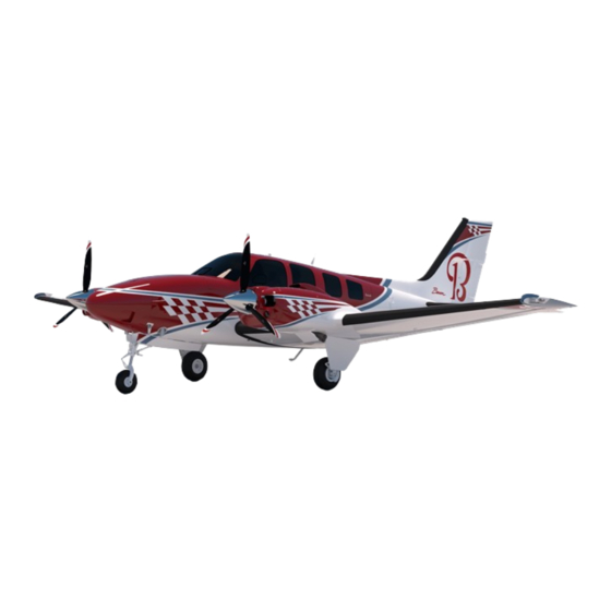
Page 46: Airplane Three View
Section 1 General Model G58 WING AREA: 199.2 SQ FT McCauley: 77 INCH DIAMETER Hartzell: 75 INCH DIAMETER 15 FT 11 IN 9 FT 7 IN 37 FT 10 IN 9 FT 9 IN 10.4 IN 8 FT 11 IN 29 FT 10 IN TH01C 054511AB.AI... -
Page 47: Ground Turning Clearance
Section 1 Model G58 General GROUND TURNING CLEARANCE RADIUS FOR WING TIP....31 FT. 6 IN. RADIUS FOR NOSE WHEEL..15 FT. 6 IN. RADIUS FOR INSIDE GEAR...7 FT. 11 IN. RADIUS FOR OUTSIDE GEAR..17 FT. 6 IN. TURNING RADII ARE PREDICATED ON THE USE OF PARTIAL BRAKING ACTION AND DIFFERENTIAL POWER. -
Page 48: Descriptive Data
Section 1 General Model G58 DESCRIPTIVE DATA ENGINES NUMBER OF ENGINES ENGINE MANUFACTURER Teledyne Continental Motors, Inc., (Mobile, Alabama) ENGINE MODEL NUMBER IO-550-C ENGINE TYPE Normally aspirated, Fuel-injected, direct-drive, air-cooled, six- cylinder, horizontally opposed, 550-cubic-inch displacement HORSEPOWER RATING 300 H.P. NUMBER OF PROPELLERS PROPELLER MANUFACTURER McCauley Propeller (Vandalia, Ohio) -
Page 49: Pitch Settings (30-Inch Station)
Section 1 Model G58 General NOTE The letters appearing in the place of the (X) represent minor variations in the propeller hub or blades. They do not affect eligibility or interchangeability. Hartzell Propellers (Optional): Constant speed, variable-pitch, three-blade propeller using a PHC-J3YF-2UF hub with FC7391D(K) blades. -
Page 50: Fuel
Section 1 General Model G58 FUEL APPROVED ENGINE FUELS Aviation Gasoline Grade 100LL (blue) Aviation Gasoline Grade 100 (green) Aviation Gasoline Grade 115/145 (purple) Chinese Aviation Gasoline RH-95/130 Chinese Aviation Gasoline RH-100/130 FUEL CAPACITY STANDARD SYSTEM Total Capacity ......200 Gallons Total Usable . -
Page 51: Engine Oil
Section 1 Model G58 General ENGINE OIL OIL CAPACITY Total ......12 Quarts (each engine) SPECIFICATION Use MIL-L-22851 Ashless Dispersant Oils meeting the require- ments of the latest revision of Teledyne Continental Motors... -
Page 52: Cabin Baggage Volumes
Section 1 General Model G58 CABIN BAGGAGE VOLUMES Aft Cabin Compartment ......37 cu ft Between Spars ....... 12 cu ft Extended Rear Compartment . - Page 53 Section 1 Model G58 General True Airspeed is the airspeed of an airplane relative to undisturbed air, which is the CAS corrected for altitude, temperature, and compressibility. Air Minimum Control Speed is the minimum flight speed at which the airplane is directionally controllable as determined in accordance with Title 14 Code of Federal Regulations.
- Page 54 Section 1 General Model G58 Maximum Flap Extended Speed is the highest speed permissible with wing flaps in a prescribed extended position. Maximum Landing Gear Extended Speed is the maximum speed at which an airplane can be safely flown with the landing gear extended.
-
Page 55: Meteorological Terminology
Section 1 Model G58 General METEOROLOGICAL TERMINOLOGY Flight in Icing Flight when the OAT is 5°C (41°F) or colder, Conditions and in the presence of visible moisture. Indicated The number actually read from an altimeter Pressure when the barometric subscale has been set Altitude 29.92 inches... -
Page 56: Power Terminology
Section 1 General Model G58 Station Actual atmospheric pressure field Pressure elevation. Wind The wind velocities recorded as variables on the charts of this handbook are to be understood as the headwind or tailwind components of the reported winds. POWER TERMINOLOGY Cruise Climb Power recommended for cruise climb. -
Page 57: Airplane Performance And Flight Planning Terminology
Section 1 Model G58 General Mixture This lever, in the idle cut-off position, stops Control the flow of fuel at the injectors and in the intermediate through the full rich positions, regulates the fuel air mixture. Propeller Used to control the RPM setting of the Control propeller governor. -
Page 58: Weight And Balance Terminology
Section 1 General Model G58 Demonstrated The velocity of the crosswind component for Crosswind which adequate control of the airplane Velocity during takeoff and landing was actually demonstrated during certification tests. The value shown is not limiting. U.S. Gallons per hour. Route A part of a route. - Page 59 Section 1 Model G58 General Jack Points Points on the airplane identified by the manufacturer as suitable for supporting the airplane for weighing or other purposes. Leveling Those points which are used during the Points weighing process to level the airplane. Maximum Maximum weight approved for ground Ramp...
-
Page 60: Acronyms
Section 1 General Model G58 Tare The weight of chocks, blocks, stands, etc., used on the scales when weighing an airplane. Unusable Fuel Fuel that is not available for flight planning. Useful Load Difference between Ramp Weight, and Basic Empty Weight. Usable Fuel Fuel available for flight planning. - Page 61 Section 1 Model G58 General Garmin: GDC ......Garmin Air Data Computer GDU ......Garmin Display Unit GEA .
- Page 62 Section 1 General Model G58 THIS PAGE INTENTIONALLY LEFT BLANK 1-26 May , 2015...
- Page 63 Model G58 SECTION 2 LIMITATIONS TABLE OF CONTENTS SUBJECT PAGE Airspeed Limitations ......2-5 Airspeed Indicator Display .
- Page 64 Model G58 SECTION 2 LIMITATIONS TABLE OF CONTENTS (CONT’D) SUBJECT PAGE Power Plant Instrument Markings (Cont’d) Oil Temperature ......2-11 Oil Pressure .
- Page 65 Model G58 SECTION 2 LIMITATIONS TABLE OF CONTENTS (CONT’D) SUBJECT PAGE Avionics ........2-16 General .
- Page 66 Section 2 Limitations Model G58 THIS PAGE INTENTIONALLY LEFT BLANK May, 2015...
-
Page 67: Airspeed Limitations
Section 2 Model G58 Limitations The limitations included in this section have been approved by the Federal Aviation Administration and must be observed in the operation of this airplane. AIRSPEED LIMITATIONS SPEED KCAS KIAS REMARKS Never Exceed Do not exceed this speed in any operation. -
Page 68: Airspeed Indicator Display
Section 2 Limitations Model G58 AIRSPEED INDICATOR DISPLAY COLOR CODED SPEED KIAS SIGNIFICANCE RANGE STRIP OR MARKING RANGE White Strip 74 - 122 Full Flap Operating Range Lower Limit = Stall speed with flaps down at maximum weight. Upper Limit = Maximum speed permissible with flaps fully extended. -
Page 69: Power Plant Limitations
Section 2 Model G58 Limitations Reference speeds for Glide, V , and V are pilot programma- ble and selectable using the TMR/REF soft key on the PFD. If one or more of these speeds is selected for display, a pointer will be positioned on the right side of the airspeed display opposite the speed that was programmed. -
Page 70: Fuel Limits
Section 2 Limitations Model G58 FUEL LIMITS APPROVED ENGINE FUELS 100LL (blue) 100 (green) 115/145 (purple) RH-95/130 (Chinese) RH-100/130 (Chinese) FUEL CAPACITY STANDARD FUEL SYSTEM Total Capacity ......200 Gallons Total Usable . -
Page 71: Number Of Propellers
Section 2 Model G58 Limitations NUMBER OF PROPELLERS PROPELLER MANUFACTURER McCauley Propeller (Vandalia, Ohio) Hartzell Propeller, Inc (Piqua, Ohio) NUMBER OF BLADES Three PROPELLER TYPE McCauley propellers (Standard): Constant-speed, variable-pitch, three-blade propeller using a 3AF32C512-(X) hub with (X)-82NEA-5 blades. NOTE The letters appearing in the place of the (X) represent minor variations in the propeller hub or blades. -
Page 72: Power Plant Instrument Markings
Section 2 Limitations Model G58 POWER PLANT INSTRUMENT MARKINGS Power Plant displays are found on the MFD on the Engine Default page, the Systems page, and the Lean page in both digital and analog formats. When the MFD is not operable, the displays are found on the PFD. -
Page 73: Fuel Flow
Section 2 Model G58 Limitations FUEL FLOW Operating Range (Green Bar) ... . . >3 to 27.4 GPH Prohibited Range (Red Bar) ... . >27.4 to 30.0 GPH Leaning Indicator (Cyan Pointer) - This pointer will automati- cally be displayed during MCP Climb and Cruise Climb power settings. -
Page 74: Miscellaneous Instrument Markings
Section 2 Limitations Model G58 Prohibited Range (Red Bar) ....0 to 10 psi Caution Range (Yellow Bar) ....>10 to 30 psi Operating Range (Green Bar). -
Page 75: Propeller Deice Ammeter
Section 2 Model G58 Limitations PROPELLER DEICE AMMETER Normal Operating Range (Green Arc) ..14 to 18 amps WEIGHT LIMITS Maximum Take-off ......5500 lbs Maximum Landing . -
Page 76: Maneuver Limits
Section 2 Limitations Model G58 MANEUVER LIMITS This is a normal category airplane. Acrobatic maneuvers, including spins, are prohibited. FLIGHT LOAD FACTORS (5500 Pounds) Positive Maneuvering Load Factors: Flaps Up (0°) .......3.8 G Flaps Down (30°) . -
Page 77: Limitations When Encountering Severe Icing Conditions (Required By Faa Ad 98-04-24)
Section 2 Model G58 Limitations Ground use of windshield heat is limited to 10 minutes at a time. Sustained flight in icing conditions with flaps extended is pro- hibited except for approach and landings. LIMITATIONS WHEN ENCOUNTERING SEVERE ICING CONDITIONS (Required By FAA AD 98- 04-24) Severe icing may result from environmental conditions outside of those for which the... -
Page 78: Avionics
[NOTE: This supersedes any relief provided by the Mas- ter Minimum Equipment List (MMEL).] AVIONICS GENERAL 1. The appropriate Garmin G1000 Cockpit Reference Guide for the Beechcraft Baron 58/G58, must be imme- diately available to the flight crew. COCKPIT REFERENCE AIRFRAME SYSTEM GUIDE P/N SOFTWARE VERSION 0500.01, 0500.02... -
Page 79: Garmin G1000 Integrated Avionics System
Refer to the MFD upon initial power up. The “Splash Screen” will display the current system software ver- sion at the top of the page, (e.g. “Beechcraft 58/G58 System 0857.05”). b. Select the SYSTEM STATUS page of the AUX Group on the MFD. - Page 80 Model G58 The following methods may be used to determine if the soft- ware loaded in the airplane is the most current software avail- able. a. Call the Beechcraft Corporation Customer Support at 1-800-429-5372. b. Visit the http://www.beechcraft.com/ customer_support/technical_publications/ web site.
- Page 81 Section 2 Model G58 Limitations AIRFRAME SYSTEM SOFTWARE VERSION 0500.02 SYSTEM ABBREVIATION SOFTWARE VERSION Primary Flight Display PFD1 6.00 Multifunction Display MFD1 6.00 Audio Control Panel & GMA1 2.07 Marker Beacon System Attitude and Heading GRS1 2.03 Reference System (AHRS) Air Data Computer (ADC) GDC1 2.05...
- Page 82 Section 2 Limitations Model G58 AIRFRAME SYSTEM SOFTWARE VERSION 0857.05 SYSTEM ABBREVIATION SOFTWARE VERSION Primary Flight Display PFD1 8.10 Multifunction Display MFD1 8.10 Audio Control Panel & GMA1 3.03 Marker Beacon System Attitude and Heading GRS1 2.11 Reference System (AHRS) Air Data Computer (ADC) GDC1 3.01...
- Page 83 Section 2 Model G58 Limitations AIRFRAME SYSTEM SOFTWARE VERSION 0857.06 SYSTEM ABBREVIATION SOFTWARE VERSION Primary Flight Display PFD1 8.10 Multifunction Display MFD1 8.10 Audio Control Panel & GMA1 4.02 Marker Beacon System Attitude and Heading GRS1 2.11 Reference System (AHRS) Air Data Computer (ADC) GDC1 3.01...
- Page 84 Section 2 Limitations Model G58 DISPLAY UNITS DEFAULT SETTING RESULTS DIS. SPD Nautical (NM, KT) Distance will be shown in nautical miles and speed in knots. ALT. VS Feet (FT, FPM) Altitude will be shown in feet and vertical speed in feet per minute.
-
Page 85: Gps Navigation
Section 2 Model G58 Limitations 3. Use of the VOR/ILS receiver to fly approaches not approved for GPS require VOR/ILS navigation data to be valid on the PFD display. 4. Fuel Planning information found on the MFD by selecting the TRIP PLANNING page of the AUX Group are advi- sory only and do not replace the primary fuel quantity and fuel flow displays on the PFD. - Page 86 Section 2 Limitations Model G58 3. Navigation using the GPS system is prohibited unless the pilot verifies the currency of the Aviation Database or verifies each selected waypoint for accuracy by refer- ence to current approved data. The Aviation Database version is displayed on the MFD power-up page immedi- ately after system power-up and must be acknowledged.
- Page 87 Model G58 Baron LIMITATIONS AVIONICS GENERAL GARMIN TERRAIN AWARENESS AND WARNING SYSTEM (TAWS) (TH-2138, TH-2141 and after and prior airplanes in compliance with Service Bulletin 34-3774) 1. The terrain data base provides world coverage. The obstacle data base provides coverage for only the conti- nental U.S.
- Page 88 Model G58 Baron information for primary terrain avoidance. TAWS is intended only to enhance situational awareness. P/N 58-590000-67TC2 4 of 4 May, 2008...
- Page 89 Section 2 Model G58 Limitations 2) Operations South of 55° Latitude are prohibited between 120° East and 165° East Longitude. 5. Instrument approaches must be accomplished in accor- dance with approved instrument approach procedures that are retrieved from the GPS database. The GPS database must incorporate the current update cycle or be verified for accuracy using current approved naviga- tion data.
-
Page 90: Garmin Gfc 700 Autopilot System (Autopilot, Flight Director, Electric Trim)
Section 2 Limitations Model G58 11. Airplanes equipped with Baro VNAV: Baro VNAV is approved for enroute and terminal vertical navigation only. Baro VNAV is not approved for instru- ment approaches. GARMIN GFC 700 AUTOPILOT SYSTEM (AUTOPI- LOT, FLIGHT DIRECTOR, ELECTRIC TRIM) 1. -
Page 91: L-3 Communications Skywatch Sky497
Section 2 Model G58 Limitations 10. The autopilot system is only approved for Category I ILS approaches and non-precision approaches. 11. Airplanes with Airframe Software Version 0500.01 or 0500.02: When conducting GPS assisted intercepts of ILS final approach courses with the autopilot engaged, the ILS CDI Capture mode on the Systems Setup page of the Auxiliary Page Group must be set to Manual. -
Page 92: Garmin Terrain Awareness And Warning System (Taws)
Section 2 Limitations Model G58 GARMIN TERRAIN AWARENESS AND WARNING SYSTEM (TAWS) (TH-2138, TH-2141 and after and prior airplanes in compliance with Service Bulletin 34-3774.) 1. The terrain database provides world coverage. The obstacle database provides coverage for only the conti- nental U.S. -
Page 93: Placards/Markings
Section 2 Model G58 Limitations PLACARDS/MARKINGS Placards/markings are required to remind the flight crew and occupants of operating limitations and safety device limita- tions. The following illustrations depict placards/markings perti- nent to operations and safety of flight. On Left Side Panel TURN STROBE LIGHTS OFF WHEN TAXING IN VICINITY OF OTHER AIRCRAFT, OR WHEN FLYING IN FOG OR CLOUDS. - Page 94 Section 2 Limitations Model G58 On Instrument Panel Above MFD: E#02C 051578AA.AI On Upper Left Side Panel, Airplanes Approved for Flight In Icing Conditions: On Upper Left Side Panel, Airplanes Not Approved for Flight In Icing Conditions: On Upper Right Side of Instrument Panel (TH-2173 and After): TH02C 063324AA.AI 2-30...
- Page 95 Section 2 Model G58 Limitations FOR STANDARD 194 GALLON CAPACITY FUEL SYSTEM Between Fuel Selector Handles: FUEL SELECTOR LEFT WING RIGHT WING USE CROSS FEED 97 GAL 97 GAL IN LEVEL FLIGHT ONLY CROSS FEED DO NOT TAKE OFF IF FUEL QUANTITY GAGES INDICATE IN YELLOW ARC OR WITH LESS THAN 13 GALLONS IN EACH WING SYSTEM TH00C...
- Page 96 Section 2 Limitations Model G58 On Inboard Side of Seat Backs for 3rd and 4th Seats: On Top of Front Spar Carry-Thru Structure Between Front Seats: EMERGENCY LANDING GEAR INSTRUCTIONS TO EXTEND ENGAGE HANDLE IN REAR OF FRONT SEAT AND TURN COUNTERCLOCKWISE AS FAR AS POSSIBLE (50 TURNS) TH02C...
- Page 97 Section 2 Model G58 Limitations On Emergency Crank Access Cover: Adjacent To Cabin Door Handle: On Inside of Cabin Door Adjacent to Door Handle: May, 2015 2-33...
- Page 98 Section 2 Limitations Model G58 On Lower Sidewall Adjacent to Pilot: WARNING EMERGENCY AIRSPEED STATIC SOURCE EMERGENCY SEE PILOTS CHECK LIST OR FLIGHT MANUAL EMERGENCY PROCEDURES FOR AIRSPEED & ALTIMETER CALIBRATION ERROR NORMAL TH02C 060621AA.AI Adjacent to Openable Cabin Window Handles: 2-34 May, 2015...
- Page 99 Section 2 Model G58 Limitations On Face of Emergency Exit Latch Cover: On Emergency Exit Handle: On Openable Cabin Windows: On Window Adjacent to Pilot’s Seat: May, 2015 2-35...
- Page 100 Section 2 Limitations Model G58 On Window Adjacent to Copilot’s Seat: On Windows Adjacent to 5th and 6th Seats and 3rd & 4th For- ward Facing Seats: On Windows Adjacent to 3rd & 4th Aft Facing Club Seats: On Inside of Utility Door on Left Sidewall of Utility Compart- ment, or on Aft Bulkhead: C95TH02C0160 2-36...
- Page 101 Section 2 Model G58 Limitations On Left Sidewall of Utility Compartment or Aft Bulkhead (with utility door removal kit): C95TH02C0161 On Panel When Utility Doors are Removed: In Plain View When Nose Baggage Compartment Door is Open: On Left Side of Instrument Panel (if Air Conditioner installed): AIR COND.
- Page 102 Section 2 Limitations Model G58 Adjacent to Oil Filler Caps: TH02D 082106AA.AI Adjacent to Fuel Filler Caps: AVGAS ONLY GRADE GRADE 100LL FOR ALTERNATE FUELS SEE PILOTS OPERATING HANDBOOK CAUTION DO NOT INSERT FUEL NOZZLE MORE THAN 3" INTO TANK TH02D 082107AA.AI 2-38...
- Page 103 Section 2 Model G58 Limitations For Standard 194 Gallon Capacity Fuel System Adjacent to Fuel Filler Caps: TH02D 082105AA.AI For Optional 166 Gallon Capacity Fuel System Adjacent to Fuel Filler Caps: TH02D 082103AA.AI May, 2015 2-39...
- Page 104 Section 2 Limitations Model G58 On External Power Compartment Door: TH02D 082104AA.AI 2-40 May, 2015...
-
Page 105: Kinds Of Operations
Section 2 Model G58 Limitations KINDS OF OPERATIONS The Model G58 is approved for the following types of opera- tions when the required equipment as shown in the KINDS OF OPERATIONS EQUIPMENT LIST, is installed and operable. 1. VFR day and night 2. - Page 106 Section 2 Limitations Model G58 VFR DAY SYSTEM VFR NIGHT and/or IFR DAY EQUIPMENT IFR NIGHT ICING CONDITIONS REMARKS and/or EXCEPTIONS ELECTRICAL POWER Alternators Battery Systems COCKPIT DISPLAY SYSTEM Primary Flight Display (PFD) Multifunction Display (MFD) Integrated Avionics Unit (GIA) Attitude / Heading Unit (AHRS) Engine / Airframe Unit (GEA) Air Data Computer (ADC)
- Page 107 Section 2 Model G58 Limitations VFR DAY SYSTEM VFR NIGHT and/or IFR DAY EQUIPMENT IFR NIGHT ICING CONDITIONS REMARKS and/or EXCEPTIONS ENVIRONMENTAL Cabin Heater FLIGHT CONTROLS Aileron Trim Tab Indicator Elevator Trim Tab Indicator Rudder Trim Tab Indicator Flap System Flap Position Indicator Lights Stall Warning System FUEL...
- Page 108 Section 2 Limitations Model G58 VFR DAY SYSTEM VFR NIGHT and/or IFR DAY EQUIPMENT IFR NIGHT ICING CONDITIONS REMARKS and/or EXCEPTIONS LANDING GEAR Emergency Landing Gear Extension System Landing Gear Position Indicator Lights Landing Gear Motor and Gearbox Landing Gear Warning Horn LIGHTS Cockpit and Display Lighting System...
- Page 109 Model G58 SECTION 3 EMERGENCY PROCEDURES TABLE OF CONTENTS SUBJECT PAGE Emergency Airspeeds (5500 Lbs) ....3-4 One-Engine-Inoperative Procedures ....3-4 Controllability vs.
- Page 110 Model G58 SECTION 3 EMERGENCY PROCEDURES TABLE OF CONTENTS (CONT’D) SUBJECT PAGE Autopilot Response to Erroneous AHRS Input ..3-17 Electric Pitch Trim Failure [PTRM] ....3-17 Unscheduled Electric Pitch Trim .
-
Page 111: Emergency Procedures
Section 3 Model G58 Emergency Procedures All airspeeds quoted in this section are indicated airspeeds (IAS) and assume zero instrument error. Closed [BRACKETS] in this section denotes Warning, Caution and Advisory annunciations which appear on the PFD and MFD. NOTE The following information is presented to enable the pilot to form, in advance, a defi- nite plan of action for coping with the most... -
Page 112: Emergency Airspeeds (5500 Lbs)
Section 3 Emergency Procedures Model G58 EMERGENCY AIRSPEEDS (5500 LBS) One-Engine-Inoperative Best Angle-of-Climb (V ) . . . 95 kts One-Engine-Inoperative Best Rate-of-Climb (V ). . . 101 kts Air Minimum Control Speed (V ) ....84 kts One-Engine-Inoperative Enroute Climb . -
Page 113: Obtaining The Best Single-Engine Climb Performance
Section 3 Model G58 Emergency Procedures OBTAINING THE BEST SINGLE-ENGINE CLIMB PERFORMANCE To obtain best single-engine climb performance with one engine inoperative, the airplane must be banked 3° to 5° into the operative engine while maintaining a constant heading. DETERMINING INOPERATIVE ENGINE The following checks will help determine which engine is inop- erative: 1. -
Page 114: Engine Failure After Lift-Off And In Flight
Section 3 Emergency Procedures Model G58 ENGINE FAILURE AFTER LIFT-OFF AND IN FLIGHT An immediate landing is advisable regardless of take-off weight. Continued flight cannot be assured if take-off weight exceeds the weight determined from the TAKE-OFF WEIGHT graph. Higher take-off weights will result in a loss of altitude while retracting the landing gear and feathering the propeller. -
Page 115: Engine Fire
Section 3 Model G58 Emergency Procedures f. Alt Load ......MONITOR g. Nonessential Electrical Equipment..OFF AS REQUIRED (to reduce load on operative alternator) h. -
Page 116: Emergency Descent
Section 3 Emergency Procedures Model G58 EMERGENCY DESCENT 1. Throttles ......CLOSED 2. -
Page 117: Landing Emergencies
Section 3 Model G58 Emergency Procedures LANDING EMERGENCIES GEAR-UP LANDING NOTE The landing gear will not retract unless one of the throttles is in a position correspond- ing to approximately 15 in. Hg manifold pressure or above. If possible, choose firm sod. When assured of reaching landing site: 1. -
Page 118: Systems Emergencies
Section 3 Emergency Procedures Model G58 SYSTEMS EMERGENCIES ONE-ENGINE-INOPERATIVE OPERATION CROSSFEED NOTE The fuel crossfeed system is to be used only during emergency conditions in level flight only. Left Engine Inoperative: 1. Right Fuel Boost Pump ..... . LOW 2. -
Page 119: Electrical Smoke Or Fire
Section 3 Model G58 Emergency Procedures ELECTRICAL SMOKE OR FIRE Action to be taken must consider existing conditions and equipment installed: 1. Alternators....... .OFF 2. -
Page 120: Alternator Failure [L Alt Inop] Or [R Alt Inop]
Section 3 Emergency Procedures Model G58 ALTERNATOR FAILURE [L ALT INOP] or [R ALT INOP] Display of either [L ALT INOP] or [R ALT INOP] warning alert on the PFD: 1. MFD Softkeys ..SELECT ENGINE AND SYSTEM 2. - Page 121 Section 3 Model G58 Emergency Procedures If both alternators remain inoperative [L-R ALT INOP]: 11. Nonessential Electrical Equipment ...OFF TO CONSERVE BATTERIES 12. If Icing Conditions Exist ... . .EXIT AS SOON AS POSSIBLE 13.
-
Page 122: Avionics
Section 3 Emergency Procedures Model G58 AVIONICS AUTOPILOT FAILURES AUTOPILOT MALFUNCTION ALTITUDE LOSSES (FEET) Climb, Cruise, Descent ......79 Maneuvering . -
Page 123: Autopilot Automatic Disengagement
Section 3 Model G58 Emergency Procedures 3. A yellow flashing [YD] will be displayed for 5 seconds then extinguish. 4. The Flight Director will remain displayed but cannot be used. 5. The electric trim will be inoperative. 6. The MFD will be inoperative. AUTOPILOT AUTOMATIC DISENGAGEMENT Red Flashing [AP] and Aural Tone Red [AFCS]... -
Page 124: Autopilot Overspeed Recovery [Maxspd]
Section 3 Emergency Procedures Model G58 AUTOPILOT OVERSPEED RECOVERY [MAXSPD] If the airspeed or airspeed trend vector reaches approximately 210 KIAS, a flashing yellow [MAXSPD] will be displayed above the airspeed display and the autopilot will command a pitch up in order to decelerate the airplane below 210 KIAS. -
Page 125: Autopilot Response To Erroneous Ahrs Input
Section 3 Model G58 Emergency Procedures AUTOPILOT RESPONSE TO ERRONEOUS AHRS INPUT A failure of the AHRS may cause erroneous autopilot responses and/or electric pitch trim activations. One or more of the following indications may be present. Red [AFCS] Yellow or Red [AP] Yellow [CHECK ATTITUDE] Unexpected Roll or Pitch Deviations Erroneous Attitude Indication... -
Page 126: Unscheduled Electric Pitch Trim
Section 3 Emergency Procedures Model G58 If the red [PTRM] annunciator extinguishes: 4. Autopilot (at pilot’s discretion) ... . . ENGAGE If the red [PTRM] annunciator does not extinguish: 5. Autopilot ..... . DO NOT ENGAGE 6. -
Page 127: Air Data Computer (Adc) Failure
Section 3 Model G58 Emergency Procedures AIR DATA COMPUTER (ADC) FAILURE Yellow [AIRSPEED] Yellow [ALTITUDE FAIL] Yellow [VERT SPEED FAIL] Red X over TAS and OAT Display 1. Refer to the standby airspeed and altimeter. 2. Land as soon as practical. ATTITUDE AND HEADING REFERENCE SYSTEM (AHRS) FAILURE Yellow [ATTITUDE FAIL]... -
Page 128: Failure Of Pfd And Mfd
Section 3 Emergency Procedures Model G58 FAILURE OF PFD AND MFD 1. Transition to the Standby Instruments. 2. 121.5 MHZ will automatically be available to the pilot through the pilot’s headset. 3. Land as soon as practical. EMERGENCY COMMUNICATIONS The 121.5 MHZ Emergency frequency will be automatically loaded in the active frequency field under the following condi- tions. - Page 129 Section 3 Model G58 Emergency Procedures In all cases, a red [PULL UP] will be displayed on the PFD and the MFD TAWS page, if selected. One of the following voice alerts will be heard. REASON VOICE WARNING ALERT Violation of Required Terrain “Terrain, Terrain;...
- Page 130 Section 3 Emergency Procedures Model G58 The following procedures should be followed if any of the pre- ceding warnings occur. In IMC or at Night: 1. Wings - Level 2. Power - Maximum Allowable 3. Pitch - Increase a. Promptly and smoothly increase pitch towards an initial pitch attitude of 15°.
-
Page 131: Excessive Descent Rate Warning [Pull Up]
Section 3 Model G58 Emergency Procedures EXCESSIVE DESCENT RATE WARNING [PULL UP] Voice Warning Alert: “Pull Up” Excessive Descent Rate (EDR) Warning - A Voice warning alert and annunciators are provided if the airplane is below 5,000 feet and approaching the terrain at an excessive rate of descent in relation to the altitude above the terrain. -
Page 132: Additional Warning Annunciations
Section 3 Emergency Procedures Model G58 ADDITIONAL WARNING ANNUNCIATIONS Illumination of a warning annunciation and its associated repeating aural tone: 1. ALERTS softkey ......PRESS (Cancels aural alert and displays message in alerts window.) NOTE... -
Page 133: Cylinder Head Temperature High [Cht Hi]
Section 3 Model G58 Emergency Procedures CYLINDER HEAD TEMPERATURE HIGH [CHT HI] 1. CHT ......CONFIRM > 238°C 2. -
Page 134: Oil Pressure High [Oil Press Hi]
Section 3 Emergency Procedures Model G58 7. Land at the nearest suitable airport using the minimum power required. OIL PRESSURE HIGH [OIL PRESS HI] 1. Oil Pressure....CONFIRM > 100 psi 2. -
Page 135: Spins
Section 3 Model G58 Emergency Procedures 2. Rotate exposed red latch handle up (as indicated by placard) breaking safety wire, and push window out. NOTE Anytime the window has been opened by breaking the safety wire on the red emer- gency latch handle, the window must be reattached and wired by a qualified mechanic using a single strand of QQ-W-... -
Page 136: Severe Icing Conditions (Alternate Method Of Compliance With Faa Ad 98-04-24)
Section 3 Emergency Procedures Model G58 NOTE Federal Aviation Administration Regula- tions do not require spin demonstration of airplanes of this class; therefore, no spin tests have been conducted. The recovery technique is based on the best available information. SEVERE ICING CONDITIONS (ALTERNATE METHOD OF COMPLIANCE WITH FAA AD 98-04-24) THE FOLLOWING WEATHER CONDITIONS MAY BE CON-... - Page 137 Section 3 Model G58 Emergency Procedures 3. Do not engage the autopilot. 4. If the autopilot is engaged, hold the control wheel firmly and disengage the autopilot. 5. If an unusual roll response or uncommanded roll control movement is observed, reduce the angle-of-attack. 6.
- Page 138 Section 3 Emergency Procedures Model G58 THIS PAGE INTENTIONALLY LEFT BLANK 3-30 April, 2008...
- Page 139 Model G58 SECTION 3A ABNORMAL PROCEDURES TABLE OF CONTENTS SUBJECT PAGE Air Start........3A-3 Landing Emergencies .
- Page 140 Model G58 SECTION 3A ABNORMAL PROCEDURES TABLE OF CONTENTS (CONT’D) SUBJECT PAGE Transponder Failure ......3A-16 Engine and/or Fuel Display Failure .
-
Page 141: Air Start
Section 3A Model G58 Abnormal Procedures Closed [BRACKETS] in this section denotes Warning, Caution and Advisory alerts which appear on the PFD and MFD. AIR START The pilot should determine the reason for engine failure before attempting an airstart. 1. Alternator (inoperative engine) ....OFF 2. -
Page 142: Landing Emergencies
Section 3A Abnormal Procedures Model G58 b. Starter ......ENGAGE (to accomplish unfeathering) c. -
Page 143: One-Engine-Inoperative Go-Around
Section 3A Model G58 Abnormal Procedures ONE-ENGINE-INOPERATIVE GO-AROUND Level flight might not be possible for certain combinations of weight, temperature and altitude. In any event, DO NOT attempt a one-engine-inoperative go-around after flaps have been fully extended. 1. Power ....MAXIMUM ALLOWABLE 2. -
Page 144: Systems
Section 3A Abnormal Procedures Model G58 SYSTEMS STARTER ENGAGE [L START ENGD] or [R START ENGD] After engine start, should the starter relay remain engaged, the starter will remain energized and the starter energized Warn- ing Alert will remain illuminated. Continuing to supply power to the starter will result in eventual loss of electrical power. -
Page 145: Alternator Low Voltage [Lbus Volt Lo] Or [Rbus Volt
Section 3A Model G58 Abnormal Procedures If voltage is greater than 30 volts a failure on the voltage regu- lator is indicated: 4. Alternator (failed side)......OFF 5. -
Page 146: Circuit Breaker Tripped
Section 3A Abnormal Procedures Model G58 7. Alternator (failed side) ....BUS TIE (ties the side with the functional alternator to the inopera- tive side) 8. -
Page 147: Landing Gear Retraction After Practice Manual Extension
Section 3A Model G58 Abnormal Procedures 6. If the electrical system is operative, a positive gear down indication can be made as follows: a. LDG GR WARN and LDG GR POS LTS Circuit Breaker ..... .CHECK IN b. -
Page 148: Ice Protection
Section 3A Abnormal Procedures Model G58 NOTE The landing gear will not retract unless the throttle is in a position corresponding to approximately 15 in. Hg manifold pressure or above. ICE PROTECTION SURFACE DEICE SYSTEM Failure of the AUTO Mode: •... -
Page 149: Electrothermal Propeller Deice System
Section 3A Model G58 Abnormal Procedures ELECTROTHERMAL PROPELLER DEICE SYSTEM An abnormal reading on the Propeller Deice Ammeter indi- cates need for the following action: 1. Zero Amps: Check the propeller deice circuit breaker switch. If the cir- cuit breaker portion of the switch has tripped the switch off, wait approximately 30 seconds before resetting. -
Page 150: Emergency Static Air Source System
Section 3A Abnormal Procedures Model G58 EMERGENCY STATIC AIR SOURCE SYSTEM THE EMERGENCY STATIC AIR SOURCE SHOULD BE USED FOR CONDITIONS ANYTIME THE NORMAL STATIC SOURCE HAS BEEN OBSTRUCTED. When the airplane has been exposed to moisture and/or icing conditions (especially on the ground), the possibility of obstructed static ports should be considered. -
Page 151: Heated Pitot Tube
Section 3A Model G58 Abnormal Procedures 3. Cabin Heat Control ....PULL OUT 4. Defrost Control ..... . . PULL OUT 5. -
Page 152: Avionics
Section 3A Abnormal Procedures Model G58 If occupant in right seat can assist: 5. Hold door during and after landing to prevent it from swinging open. AVIONICS AUTOPILOT FAILURES FAILURE OF AUTOPILOT PRE-FLIGHT TEST Red [PFT] 1. AP SERVOS Circuit Breaker....PULL [PFT] - Extinguished 2. - Page 153 Section 3A Abnormal Procedures Model G58 Baron Temporary Change to the Pilot’s Operating Handbook FAA Approved Airplane Flight Manual P/N 58-590000-67TC1 Rev 1 Publication Model G58 Pilot’s Operating Handbook and Affected FAA Approved Airplane Flight Manual (58- 590000-67, Issued November, 2005) Airplane Serials TH-2125 thru TH-2158 not in compliance Numbers...
- Page 154 Section 3A Model G58 Baron Abnormal Procedures ABNORMAL PROCEDURES AVIONICS AUTOPILOT FAILURES NUISANCE PITCH PULSE If a nuisance pitch pulse is encountered, disconnect autopilot. Retrim and stabilize airplane in the desired flight path and re- engage the autopilot, if desired. P/N 58-590000-67TC1 Rev 1 2 of 4 June, 2006...
-
Page 155: Loss Of A Flight Director/Autopilot Mode
Section 3A Model G58 Abnormal Procedures If an annunciation remains illuminated: 4. Control Wheel ..... HOLD FIRMLY (be prepared to apply force in the direction of the arrow) 5. -
Page 156: Avionics Master Switch Failure
Section 3A Abnormal Procedures Model G58 4. NAV Mode ....... . ARM If on an instrument approach at the time the navigation signal is lost: 5. -
Page 157: Erroneous Failure Displays
Section 3A Model G58 Abnormal Procedures If all engine instruments are inoperative: 1. L and R ENG/AFR SENSOR Circuit Breaker ......CHECK IN If a partial failure has occurred: 2. -
Page 158: Failed Heading During Ground Operations
Section 3A Abnormal Procedures Model G58 FAILED HEADING DURING GROUND OPERA- TIONS (RED “X” OVER [HDG] FLAG ON PFD) Interference from GPS repeaters operating inside nearby han- gars or magnetic anomalies caused by nearby structures can cause an intermittent loss of heading display while the airplane is on the ground. -
Page 159: [Mfd Fan Fail] Or [Avionics Fan]
Section 3A Model G58 Abnormal Procedures GLOBAL POSITIONING SYSTEM (GPS) LOSS OF, OR INVALID GPS SIGNAL • Utilize NAV 1 or NAV 2 receivers. POSITION ERROR [POSN ERROR] 1. GPS signal will flag. 2. Utilize NAV 1 or NAV 2 receivers. LOSS OF RECEIVER AUTONOMOUS INTEGRITY MONITORING (RAIM) During enroute, oceanic, terminal, or initial approach phase of... -
Page 160: Garmin Terrain Awareness And Warning System (Taws)
Section 3A Abnormal Procedures Model G58 GARMIN TERRAIN AWARENESS AND WARNING SYSTEM (TAWS) (TH-2138, TH-2141 and after and prior airplanes in compli- ance with Service Bulletin. 34-3774.) TAWS FORWARD LOOKING TERRAIN CAUTIONS [TERRAIN] Voice Caution Alert: See the following table. Reduced Required Terrain (or Obstacle) Clearance (RTC or ROC) Caution - Voice caution alerts and annunciators are pro- vided if the airplane flight path is projected to violate a set of... -
Page 161: Excessive Descent Rate Caution [Terrain]
Section 3A Model G58 Abnormal Procedures NOTE When the TAWS Page is not displayed and a terrain or obstacle caution is issued, a pop-up window is displayed in the lower right corner of the MFD displaying an appropriate annunciator. See Section 7, SYSTEMS DESCRIPTION. -
Page 162: Negative Climb Rate After Takeoff [Terrain]
Section 3A Abnormal Procedures Model G58 NOTE When the TAWS Page is not displayed, and an EDR caution is issued, a pop-up window is displayed in the lower right cor- ner of the MFD displaying a yellow [SINK RATE]. The following procedure should be followed if the above cau- tion occurs. -
Page 163: Premature Descent During An Approach [Terrain]
Section 3A Model G58 Abnormal Procedures PREMATURE DESCENT DURING AN APPROACH [TERRAIN] Voice Caution Alert: “Too Low, Terrain” A Voice caution alert and annunciator are provided to alert the pilot that the airplane has descended too low for the particular kind of approach;... -
Page 164: Additional Caution Annunciations
Section 3A Abnormal Procedures Model G58 The GPS ALT displayed on the MFD is a calculated value and must not be consid- ered as a primary source of altitude. The GPS ALT and the altitude displayed on the PFD may differ by 100 feet or more. Its use is not approved for navigation. -
Page 165: Oil Pressure Low [Oil Press
Section 3A Model G58 Abnormal Procedures OIL PRESSURE LO [OIL PRESS LO] 1. Oil Pressure ....CONFIRM < 30 psi If confirmed: 2. -
Page 166: Surface Deice Air Pump [L Air Pump] Or [R Air Pump]
Section 3A Abnormal Procedures Model G58 Depending on the cause of the Bus Over- load condition, battery operating time on the affected side may be less than 30 min- utes. When power to the Left Bus is only being supplied by the battery, be prepared to use standby instruments. - Page 167 Model G58 SECTION 4 NORMAL PROCEDURES TABLE OF CONTENTS SUBJECT PAGE Airspeeds For Safe Operation (5500 Lbs) ... 4-5 Preflight Inspection ......4-6 Before Engine Starting .
- Page 168 Model G58 SECTION 4 NORMAL PROCEDURES TABLE OF CONTENTS (CONT’D) SUBJECT PAGE Standby Attitude Indicator ..... . . 4-26 After Starting ....... 4-26 Before Takeoff .
- Page 169 Model G58 SECTION 4 NORMAL PROCEDURES TABLE OF CONTENTS (CONT’D) SUBJECT PAGE Ice Protection Systems......4-50 Before Takeoff .
- Page 170 Section 4 Model G58 Normal Procedures THIS PAGE INTENTIONALLY LEFT BLANK June, 2011...
- Page 171 Minimum During Icing Conditions....130 kts NOTE Refer to all applicable Hawker Beechcraft Corpo- ration Supplements and STC Supplements for flight phase procedures for optional equipment installed in the airplane.
- Page 172 Section 4 Normal Procedures Model G58 PREFLIGHT INSPECTION TH04C 054024AA.AI 1. CABIN a. Emergency Exits..... . . CHECK 1) Safety Wire (Beneath Cover)..INTACT 2) Windows .
- Page 173 Section 4 Model G58 Normal Procedures 2. COCKPIT a. Landing Gear Emergency Handcrank ..STOWED AND ACCESSIBLE b. Fire Extinguisher ..... . CHECK c.
- Page 174 Section 4 Normal Procedures Model G58 4. EMPENNAGE a. Vertical & Horizontal Stabilizers ... CHECK b. Deice Boots ......CHECK c.
- Page 175 Section 4 Model G58 Normal Procedures b. Fuel ..CHECK QTY, O RING, CAP SECURE (Always check wing tip tank (if installed) first; do not remove inboard cap if fuel is visible in tip tank.) c.
- Page 176 Section 4 Normal Procedures Model G58 8. NOSE SECTION a. OAT Probe ......CHECK b.
- Page 177 Section 4 Model G58 Normal Procedures 5) Shock Strut ... . . PROPER INFLATION 6) Tire ......CONDITION 7) Chocks .
- Page 178 Section 4 Normal Procedures Model G58 BEFORE ENGINE STARTING 1. Seats ....POSITION FOR TAKEOFF 2. Rudder Pedals......ADJUST 3.
- Page 179 Section 4 Model G58 Normal Procedures c. With Partial Fuel (if required) ..Press DEC FUEL or INC FUEL (to adjust GAL REM) 23. Fuel Selector Valves ......ON (feel for detent;...
- Page 180 Section 4 Normal Procedures Model G58 5. Throttle ....CLOSE, THEN OPEN APPROXIMATELY 1/2 INCH 6. Magnetos/Start Switch ....START (Release to BOTH when engine starts) •...
- Page 181 Section 4 Model G58 Normal Procedures 5. Throttle ......FULL OPEN 6. Fuel Boost Pump ..HI UNTIL FUEL FLOW PEAKS THEN OFF 7.
- Page 182 Section 4 Normal Procedures Model G58 8. Electrical System......CHECK a. MFD Soft Keys . . . SELECT ENGINE AND SYSTEM b.
- Page 183 Section 4 Model G58 Normal Procedures c. TEST Softkey ......PRESS 1) Test Pattern....VERIFY ON MFD 2) [TRAFFIC] .
- Page 184 Section 4 Normal Procedures Model G58 14. Standby Altimeter ......SET 15. Brakes ....RELEASE AND CHECK Never taxi with a flat shock strut BEFORE TAKEOFF (RUNUP) 1.
- Page 185 Section 4 Model G58 Normal Procedures 11. Electric Elevator Trim ..... CHECK a. Left and Right Segments ....ACTUATE INDIVIDUALLY (verify there is no trim movement.
- Page 186 Section 4 Normal Procedures Model G58 BEFORE TAKEOFF (FINAL ITEMS) 1. Ice Protection Systems ....AS REQUIRED 2. Lights......AS REQUIRED 3.
- Page 187 Section 4 Model G58 Normal Procedures 2. Cowl Flaps ..... . . AS REQUIRED 3. Airspeed ....105 KTS FOR MCP CLIMB 136 KTS FOR CRUISE CLIMB 4.
- Page 188 Section 4 Normal Procedures Model G58 CRUISE 1. Cowl Flaps......CLOSE 2.
-
Page 189: Before Landing
Section 4 Model G58 Normal Procedures 7. Windshield Defroster....AS REQUIRED (ON before descent into warm, moist air) 8. Descent Speed ....RECOMMENDED 16,000 to 13,000 ft . - Page 190 Section 4 Normal Procedures Model G58 AFTER LANDING 1. Landing, Taxi and Strobe Lights ..AS REQUIRED 2. Flaps ........UP 3.
- Page 191 Section 4 Model G58 Normal Procedures OTHER NORMAL PROCEDURES EXTERNAL POWER The following precautions shall be observed using external power: 1. Batteries must be installed in the airplane. This protects the voltage regulators and associated equipment from voltage transients (power fluctuations). 2.
-
Page 192: Standby Attitude Indicator
Section 4 Normal Procedures Model G58 14. L ALT and R ALT......ON 15. -
Page 193: Shutdown
Section 4 Model G58 Normal Procedures If the red test LED illuminates any time dur- ing the one minute test, the standby battery is not sufficiently charged. This may indi- cate that additional charging is required, or that the standby battery must be removed for service or replacement. - Page 194 Section 4 Normal Procedures Model G58 NOTE A momentary pause must occur between each push of the STBY PWR button. If the second push of the button occurs too quickly, it will not be recognized. If the pro- cessor detects only one push of the STBY PWR button the standby battery will be latched on and continue to power the indi- cator.
-
Page 195: Leaning Using The Exhaust Gas Temperature (Egt) Indication
Section 4 Model G58 Normal Procedures 6. R BAT ........OFF •... -
Page 196: Monitoring Engine Systems (Oil, Fuel, Electrical)
Section 4 Normal Procedures Model G58 3. The engine should not be operated closer to peak EGT than 20°C (rich side or lean side) as indicated on the MANIFOLD PRESSURE vs RPM graph (Section 5, PERFORMANCE). 4. If engine roughness is encountered operating at lower power settings on the lean side of peak, enrich the mix- ture slightly for smooth engine operation. - Page 197 Section 4 Model G58 Baron Normal Procedures NORMAL PROCEDURES AVIONICS AUTOPILOT/FLIGHT DIRECTOR GENERAL NOTE If above 150 KTS, operation in the PIT mode can result in nuisance pitch pulsing when using the NOSE-UP or NOSE-DOWN command keys. Transition to ALT, FLC or VS mode prior to using NOSE-UP or NOSE- DOWN keys.
-
Page 199: Monitoring The Chts And Egts
Section 4 Model G58 Normal Procedures MONITORING THE CHT AND EGT Specific EGT and CHT values for each cylinder are found on the MFD. 1. ENGINE Soft Key ......PRESS 2. -
Page 200: Autopilot/Flight Director Procedures
Section 4 Normal Procedures Model G58 The pilot must use proper autopilot modes and proper engine power settings to ensure that airplane speed is maintained between 90 KTS and 210 KTS. Operation in the pitch (PIT) or vertical speed (VS) modes below 90 KTS can result in a stall. If an inadvertent stall is encountered as indicated by the stall warning horn, airframe buffeting, or loss of control effective- ness, disconnect the autopilot using the AP DISC switch and... - Page 201 Section 4 Model G58 Normal Procedures Engaging the Autopilot (90 - 210 KTS) 1. AP Key ..PRESS TO ENGAGE AUTOPILOT & YD green [ROL], [AP], [YD], [PIT], & white [ALT] Displayed 2. ALT Key ..PRESS TO HOLD EXISTING ALTITUDE [PIT] &...
- Page 202 Section 4 Normal Procedures Model G58 Use of Roll Mode [ROL] 1. AP Key ..PRESS TO ENGAGE AUTOPILOT & YD green [ROL], [AP], [YD], [PIT], & white [ALT] Displayed If bank angle is 6°: 2.
- Page 203 Section 4 Model G58 Normal Procedures 4. HDG Key....... PRESS [HDG] Displayed 5.
- Page 204 Section 4 Normal Procedures Model G58 e. If the indicated altitude deviates more than ± 200 feet, the altitude reference box will change to yellow digits on a black background and will flash for 5 seconds. A tone will be heard. The yellow display will remain until the deviation is corrected or the desired altitude is changed.
- Page 205 Section 4 Model G58 Normal Procedures Use of Altitude Hold Mode [ALT] To Maintain a desired altitude: 1. ALT Key ....... PRESS Green [ALT XXXXX ] Displayed To change the selected altitude:...
- Page 206 Section 4 Normal Procedures Model G58 NOTE If the VNV softkey is pressed more than 5 minutes before the top of descent (TOD) or the altitude preselect is not reset to a lower altitude, VPTH will begin to flash inverse video (white/black) when the aural “Vertical Track”...
- Page 207 Section 4 Model G58 Normal Procedures Use of the Vertical Speed Mode [VS] 1. ALT Knob ..SET DESIRED LEVEL-OFF ALTITUDE a. Preset Altitude is displayed in window above the altimeter display. NOTE If the Flight Director is in Altitude Hold (green [ALT XXXXX ] displayed in the AFCS status bar), the desired altitude must...
- Page 208 Section 4 Normal Procedures Model G58 6. Maximum and minimum VS references are 1500 fpm R/C and -3000 fpm R/S. NOTE The VS pointer will only indicate a maxi- mum of -2000 FPM; however, the digits in the pointer will continue to indicate the ver- tical speed up to -3000 FPM.
-
Page 209: Approach Procedures
Section 4 Model G58 Normal Procedures 3. NOSE UP or NOSE DN Key ..PRESS AS REQ TO SET CLIMB OR DESCENT SPEED (each press changes speed by 1 knot) (or) 4. CWS Switch ... . PRESS AND HOLD WHILE ADJUSTING PITCH TO CHANGE AIRSPEED, THEN RELEASE (FLC airspeed reference will change... - Page 210 Section 4 Normal Procedures Model G58 GPS Approach [GPS] (Software Version 0500.01 or 0500.02) 1. CDI Key ......SELECTED GPS 2.
- Page 211 Section 4 Model G58 Normal Procedures GPS Approach [LNAV+V] (Software Version 0857.05 or 0857.06) 1. Baro Minimums ......SET 2.
- Page 212 Section 4 Normal Procedures Model G58 Go Around [GA] & [GA] (With an Active Approach Loaded) (Software Version 0500.01 or 0500.02) 1. Go Around Button on Throttle ....PRESS 2.
-
Page 213: Traffic Information Service (Tis)
Section 4 Model G58 Normal Procedures 9. CWS ....PRESS TO CNX GA MODE & ADJUST PITCH 10. HDG or NAV Key ......PRESS TRAFFIC INFORMATION SERVICE (TIS) 1. -
Page 214: Cold Weather Operation
Section 4 Normal Procedures Model G58 COLD WEATHER OPERATION PREFLIGHT INSPECTION Verify that the tires are not frozen to the ramp, and that the brakes are free of ice contamination. Deicing or anti-icing solu- tions may be used on the tires and brakes if they are frozen. Solutions which contain a lubricant, such as oil, must not be used as they will decrease the effectiveness of the brakes. -
Page 215: After Starting
Section 4 Model G58 Normal Procedures Under very cold conditions, it may be necessary to preheat the engines prior to a start. Particular attention should be given to the oil cooler, engine sump and propeller hub to ensure proper preheat. A start with congealed oil in the system may produce an indication of normal pressure immediately after the start, but then the oil pressure may decrease when residual oil in the engine is pumped back with the congealed oil in the sump. -
Page 216: Before Takeoff
Section 4 Normal Procedures Model G58 BEFORE TAKEOFF After completion of the normal Before Takeoff checklist, verify that the airplane is still free of frozen contaminants. Ensure the runway is free from hazards such as snow drifts, glazed ice, and ruts. TAKEOFF Allow additional take-off distance when snow or slush is on the runway. -
Page 217: Heater Operation
Section 4 Model G58 Normal Procedures HEATER OPERATION NOTE During preflight, ensure the heater over- temperature switch located on the aft end of the heater is not tripped. Push the switch in to reset, if required. 1. Cabin Vent Air Control ... ON (½ OR MORE) NOTE Heater will not operate if control is pulled aft more than half way. -
Page 218: Windshield Defogging
Section 4 Normal Procedures Model G58 NOTE Blower must be left on for a minimum of two minutes after turning the heater off to ensure heater does not over temp causing the over-temperature switch to open. WINDSHIELD DEFOGGING To Achieve Maximum Windshield Defogging: 1. -
Page 219: Before Takeoff
Section 4 Model G58 Normal Procedures BEFORE TAKEOFF CABIN HEATER 1. Cabin Vent Air Control ..ON (1/2 OR MORE) 2. Heater Switch .......ON 3. -
Page 220: Fuel Vent Heat, Stall Warning Heat, Pitot Heat, Windshield Heat, And Ice Light
Section 4 Normal Procedures Model G58 FUEL VENT HEAT, STALL WARNING HEAT, PITOT HEAT, WINDSHIELD HEAT, AND ICE LIGHT 1. MFD Soft Keys ..SELECT ENGINE AND SYSTEM 2. Switches ..CYCLE ON AND OFF, ONE AT A TIME 3. -
Page 221: Surface Deice System
Section 4 Model G58 Normal Procedures SURFACE DEICE SYSTEM NOTE Deicing pressure gage will indicate approxi- mately 5 psi during periods when boots are not utilized. When ice accumulates 1/2 to 1 inch: 1. Surface Deice ......AUTO (up) 2. -
Page 222: Electrothermal Heated Windshield Segment
Section 4 Normal Procedures Model G58 ELECTROTHERMAL HEATED WINDSHIELD SEGMENT Prior to Entering Icing Conditions: • Windshield Heat ....... . ON NOTE Continuous operation is permitted. -
Page 223: Practice Demonstration Of Vmca
Section 4 Model G58 Normal Procedures PRACTICE DEMONSTRATION OF V demonstration may be required for multi-engine pilot cer- tification. The following procedure shall be used at a safe alti- tude of at least 5000 feet above the ground in clear air only. INFLIGHT ENGINE CUTS BELOW V SPEED OF 88 KTS ARE PROHIBITED. -
Page 224: Engine Break-In Information
Section 4 Normal Procedures Model G58 ENGINE BREAK-IN INFORMATION Refer to Section 7, SYSTEMS DESCRIPTION. NOISE CHARACTERISTICS Approach to and departure from an airport should be made so as to avoid prolonged flight at low altitude near noise-sensitive areas. Avoidance of noise-sensitive areas, if practical, is pref- erable to overflight at relatively low altitudes. - Page 225 Model G58 Section 5 Performance TABLE OF CONTENTS SUBJECT PAGE Introduction To Performance ..... 5-5 Performance In Icing Conditions ....5-5 How To Use The Graphs .
- Page 226 Model G58 Section 5 Performance TABLE OF CONTENTS (CONT’D) SUBJECT PAGE Take-Off Weight ......5-25 Wind Components.
- Page 227 Model G58 Section 5 Performance TABLE OF CONTENTS (CONT’D) SUBJECT PAGE Endurance Profile - 194 Gallons - Rich ... . . 5-48 Endurance Profile - 194 Gallons - Lean ... . . 5-49 Holding Time .
- Page 228 Section 5 Performance Model G58 THIS PAGE INTENTIONALLY LEFT BLANK July, 2014...
-
Page 229: Introduction To Performance
Section 5 Model G58 Performance Except as noted, all airspeeds quoted in this section are indi- cated airspeeds (IAS) and assume zero instrument error. INTRODUCTION TO PERFORMANCE The graphs and tables in this section present performance information for flight planning at various parameters of weight, power, altitude and temperature. -
Page 230: How To Use The Graphs
Section 5 Performance Model G58 HOW TO USE THE GRAPHS 1. In addition to presenting the answer for a particular set of conditions, the example on the graph also presents the order in which the various scales on the graph should be used. -
Page 231: Example Calculations
Section 5 Model G58 Performance EXAMPLE CALCULATIONS The calculations for flight time, block speed and fuel required for a proposed flight are listed below: CONDITIONS At Departure: Outside Air Temperature ....15°C (59°F) Field Elevation . -
Page 232: Pressure Altitude
Section 5 Performance Model G58 PRESSURE ALTITUDE To determine pressure altitude at departure and destination airports, add 1000 ft to field elevation for each 1.00 in. Hg below 29.92, and subtract 1000 ft from field elevation for each 1.00 in. Hg above 29.92. Pressure Altitude at Departure: 29.92 - 29.60 = 0.32 in. -
Page 233: Take-Off Distance
Section 5 Model G58 Performance Enter the Take-Off Weight graph at 5653 ft pressure altitude and 15°C, to determine the maximum take-off weight to achieve a positive one-engine-inoperative rate-of-climb at lift- off. Take-off Weight = 4870 lbs TAKE-OFF DISTANCE Enter the Take-Off Distance graph at 15°C, 5653 ft pressure altitude, 5500 lbs, and 10 knots headwind component: Ground Roll . - Page 234 Section 5 Performance Model G58 Enter the Accelerate-Go graph at 15°C, 5653 ft pressure alti- tude, 4700 lbs, and 10 knots headwind component: Total Distance Over 50-ft Obstacle ... . . 9400 ft Ground Roll Distance.
-
Page 235: Cruise Climb
Section 5 Model G58 Performance The results are illustrated as follows: FLIGHT TIME, BLOCK SPEED FUEL REQUIREMENT CRUISE CLIMB Enter the TIME, FUEL AND DISTANCE TO CRUISE CLIMB Graph at the takeoff temperature of 15°C and trace up to 5653 ft pressure altitude. -
Page 236: Cruise
Section 5 Performance Model G58 Time to Climb = (13 - 5) = 8 min Fuel Used to Climb = (9.5 - 3.9) = 5.6 gal Distance Traveled = (32 - 11.5) = 20.5 nm CRUISE The air temperatures for cruise are presented for 20°C below a Standard Day (ISA -20°C), for a Standard Day (ISA) and for 20°C above a Standard Day (ISA +20°C). - Page 237 Section 5 Model G58 Performance Interpolate for 11,500 ft and the temperature for the appropri- ate route segment. Results of the interpolations are: ROUTE ISA CONDITION FUEL FLOW SEGMENT PER ENG KNOTS GAL/HR LEG A-B ISA + 3°C 14.0 LEG C ISA + 8°C 13.9 LEG D...
-
Page 238: Descent
Section 5 Performance Model G58 DESCENT Enter the TIME, FUEL, and DISTANCE TO DESCEND Graph at the cruise pressure altitude of 11,500 ft and trace right to the reference line. Then trace down to obtain the time, fuel, and distance to descend to S.L. Repeat the process starting with destination field pressure altitude of 3965 ft. -
Page 239: Total Fuel Required
Section 5 Model G58 Performance Total Fuel Flow ......17.4 gph Reserve Fuel (45 minutes) (17.4 gph)... 13.1 gal TOTAL FUEL REQUIRED Total Fuel Required = Calculated Fuel Usage + Reserve Fuel Total Fuel Required... - Page 240 Section 5 Performance Model G58 Enter the CLIMB-BALKED LANDING graph at 25°C, 3965 ft pressure altitude and 5166 lbs: Rate-of-Climb......765 ft/min Climb Gradient .
- Page 241 Section 5 Model G58 Performance July, 2014 5-17...
- Page 242 Section 5 Performance Model G58 5-18 July, 2014...
- Page 243 Section 5 Model G58 Performance July, 2014 5-19...
- Page 244 Section 5 Performance Model G58 5-20 July, 2014...
- Page 245 Section 5 Model G58 Performance July, 2014 5-21...
- Page 246 Section 5 Performance Model G58 5-22 July, 2014...
- Page 247 Section 5 Model G58 Performance 5-23 July, 2014...
- Page 248 Section 5 Performance Model G58 5-24 July, 2014...
- Page 249 Section 5 Model G58 Performance 5-25 July, 2014...
- Page 250 Section 5 Performance Model G58 5-26 July, 2014...
- Page 251 Section 5 Model G58 Performance July, 2014 5-27...
- Page 252 Section 5 Performance Model G58 5-28 July, 2014...
- Page 253 Section 5 Model G58 Performance July, 2014 5-29...
- Page 254 Section 5 Performance Model G58 5-30 July, 2014...
- Page 255 Section 5 Model G58 Performance July, 2014 5-31...
- Page 256 Section 5 Performance Model G58 5-32 July, 2014...
- Page 257 Section 5 Model G58 Performance SERVICE CEILING - ONE-ENGINE-INOPERATIVE CLIMB SPEED: 101 KNOTS (ALL WEIGHTS) ASSOCIATED CONDITIONS: EXAMPLE: POWER MAXIMUM CONTINUOUS -20°C LANDING GEAR WEIGHT 4700 LBS INOPERATIVE PROPELLER FEATHERED SERVICE CEILIN 12,015 F FLAPS MIXTURE AS REQUIRED BY ALTITUDE NOTE: ONE-ENGINE-INOPERATIVE SERVICE CEILING IS THE MAXIMUM PRESSURE ALTITUDE AT WHICH THE AIRPLANE HAS THE CAPABILITY OF CLIMBING AT 50 FT/MINUTE WITH ONE PROPELLER FEATHERED.
- Page 258 Section 5 Performance Model G58 5-34 July, 2014...
- Page 259 Section 5 Model G58 Performance THIS PAGE INTENTIONALLY LEFT BLANK 5-35 July, 2014...
- Page 260 Section 5 Performance Model G58 CRUISE POWER SETTINGS MAXIMUM CRUISE POWER 20°C RICH 25 IN. HG (OR FULL THROTTLE) @ 2500 RPM (5200 LBS.) OF PEAK EGT PRESS. MAN. FUEL FLOW AIR- ALT. PRESS. /ENGINE SPEED FEET °C °F IN. HG GPH KIAS KTAS 16.8 2000...
- Page 261 Section 5 Model G58 Performance CRUISE POWER SETTINGS RECOMMENDED CRUISE POWER 20°C LEAN 25 IN. HG (OR FULL THROTTLE) @ 2500 RPM (5200 LBS.) OF PEAK EGT PRESS. MAN. FUEL FLOW AIR- ALT. PRESS. /ENGINE SPEED FEET °C °F IN. HG GPH KIAS KTAS 14.5 2000...
- Page 262 Section 5 Performance Model G58 CRUISE POWER SETTINGS RECOMMENDED CRUISE POWER 20°C RICH 23 IN. HG (OR FULL THROTTLE) @ 2300 RPM (5200 LBS.) OF PEAK EGT PRESS. MAN. FUEL FLOW AIR- ALT. PRESS. /ENGINE SPEED FEET °C °F IN. HG GPH KIAS KTAS 13.5 2000...
- Page 263 Section 5 Model G58 Performance CRUISE POWER SETTINGS RECOMMENDED CRUISE POWER 20°C LEAN 23 IN. HG (OR FULL THROTTLE) @ 2300 RPM (5200 LBS.) OF PEAK EGT PRESS. MAN. FUEL FLOW AIR- ALT. PRESS. /ENGINE SPEED FEET °C °F IN. HG GPH KIAS KTAS 11.2 2000...
- Page 264 Section 5 Performance Model G58 5-40 July, 2014...
- Page 265 Section 5 Model G58 Performance 5-41 July, 2014...
- Page 266 Section 5 Performance Model G58 5-42 July, 2014...
- Page 267 Section 5 Model G58 Performance July, 2014 5-43...
- Page 268 Section 5 Performance Model G58 5-44 July, 2014...
- Page 269 Section 5 Model G58 Performance July, 2014 5-45...
- Page 270 Section 5 Performance Model G58 5-46 July, 2014...
- Page 271 Section 5 Model G58 Performance July, 2014 5-47...
- Page 272 Section 5 Performance Model G58 5-48 July, 2014...
- Page 273 Section 5 Model G58 Performance July, 2014 5-49...
- Page 274 Section 5 Performance Model G58 HOLDING TIME (APPLICABLE FOR ALL TEMPERATURES) ASSOCIATED CONDITIONS: EXAMPLE: POWER SETTINGS 21 IN. HG FUEL AVAILABLE FOR OR FULL THROTTLE HOLDING 50 GAL AT 2100 RPM PRESSURE ALTITUDE 11,500 FT MIXTURE 20°C LEAN OF PEAK EGT HOLDING TIME 2.6 HRS WEIGHT...
- Page 275 Section 5 Model G58 Performance 5-51 July, 2014...
- Page 276 Section 5 Performance Model G58 5-52 July, 2014...
- Page 277 Section 5 Model G58 Performance July, 2014 5-53...
- Page 278 Section 5 Performance Model G58 THIS PAGE INTENTIONALLY LEFT BLANK 5-54 July, 2014...
- Page 279 Model G58 SECTION 6 WEIGHT AND BALANCE/EQUIPMENT LIST TABLE OF CONTENTS SUBJECT PAGE Basic Empty Weight and Balance - Actual ... 6-3 Sample Loading ....... . . 6-4 Introduction .
- Page 280 Section 6 Wt and Bal/Equip List Model G58 THIS PAGE INTENTIONALLY LEFT BLANK December, 2009...
-
Page 281: Basic Empty Weight And Balance - Actual
Section 6 Model G58 Wt and Bal/Equip List BASIC EMPTY WEIGHT AND BALANCE - ACTUAL (THIS PAGE TO BE REPLACED UPON AIRCRAFT DELIVERY) December, 2009... -
Page 282: Sample Loading
Section 6 Wt and Bal/Equip List Model G58 SAMPLE LOADING (THIS PAGE TO BE REPLACED UPON AIRCRAFT DELIVERY) December, 2009... -
Page 283: Introduction
Weight and Balance Record in this POH/AFM Section, or similar form, be used. The current Equipment List and Basic Empty Weight and Balance data must stay with the airplane when it changes ownership. Hawker Beechcraft Cor- poration cannot maintain the current airplane configuration sta- tus. -
Page 284: Weighing Instructions
Section 6 Wt and Bal/Equip List Model G58 WEIGHING INSTRUCTIONS DIMENSIONAL DATA December, 2009... - Page 285 Section 6 Model G58 Wt and Bal/Equip List Periodic weighing of the airplane may be required to keep the Basic Empty Weight current. All changes to the airplane affect- ing weight and balance are the responsibility of the airplane’s owner and/or operator. 1.
- Page 286 Section 6 Wt and Bal/Equip List Model G58 6. Measurement of the reaction arms for a wheel weighing is made using a steel measuring tape. Measurements are taken with the airplane level on the scales, from the reference (a plumb bob dropped from the center of either main jack point) to the axle center line of the main gear and then to the nose wheel axle center line.
- Page 287 Section 6 Model G58 Wt and Bal/Equip List E#06C 022632AA.AI December, 2009...
- Page 288 Section 6 Wt and Bal/Equip List Model G58 6-10 December, 2009...
- Page 289 Section 6 Model G58 Wt and Bal/Equip List 6-11 December, 2009...
- Page 290 Section 6 Wt and Bal/Equip List Model G58 FS -10.0 BAGGAGE FS 15.0 FS 39.0 (FRONT CREW FS 75.0 (PILOT) SEAT PASS.) TO FS 82.0 BAGGAGE FS 108.0 (3RD (4TH AFT FACING PASS FWD FACING PASS SEAT SEAT PASS.) PASS.) FS 111.0 TO FS 115.0 FS 115.0 TO FS 120.0 BAGGAGE...
- Page 291 Section 6 Model G58 Wt and Bal/Equip List 5700 78.3 5600 MAX RAMP WT - 5524 LB 5500 MAX TAKE-OFF WT MAX LANDING WT 5400 5300 5200 5100 5000 4900 4800 4700 4600 4500 4400 4300 4200 4100 4000 3900 3800 3700 3600...
-
Page 292: Moment Limits Vs Weight Table
Section 6 Wt and Bal/Equip List Model G58 MOMENT LIMITS vs. WEIGHT TABLE WEIGHT MOMENT/100 (lb-in. ) (lb) FWD LIMIT AFT LIMIT 3800 2812 3268 3850 2849 3311 3900 2886 3354 3950 2923 3397 4000 2960 3440 4050 2997 3483 4100 3034 3526... -
Page 293: Loading Computing Procedure
Section 6 Model G58 Wt and Bal/Equip List LOADING COMPUTING PROCEDURE NOTE Loadings may be prepared accumulating weights and moments/100 only and using the Moment Limits vs. Weight Table for Step 10. compliance. Or, by also including the calculated arms as indicated and using the Weight and Balance Diagram for Step 10. - Page 294 Section 6 Wt and Bal/Equip List Model G58 6. Copy the fuel load weight only from Line 11. to Line 15. 7. Off to the side, add the calculated fuel to destination to the Start, Taxi and Run-Up fuel. Record the total weight only on line 16.
-
Page 295: Weight And Balance Loading Form
Section 6 Model G58 Wt and Bal/Equip List WEIGHT AND BALANCE LOADING FORM Serial No.: ______________ Date: ___________ MOMENT WEIGHT LINE ITEM (lb) (in.) (lb-in.) BASIC EMPTY WEIGHT 2. Pilot and Front Seat Passenger 3. 3rd and/or 4th Seat Passengers 4. - Page 296 Section 6 Wt and Bal/Equip List Model G58 WEIGHT AND BALANCE LOADING FORM Serial No.: ______________ Date: ___________ MOMENT WEIGHT LINE ITEM (lb) (in.) (lb-in.) BASIC EMPTY WEIGHT 2. Pilot and Front Seat Passenger 3. 3rd and/or 4th Seat Passengers 4.
-
Page 297: Useful Load - Payload, Weights And Moments Table
Section 6 Model G58 Wt and Bal/Equip List USEFUL LOAD - PAYLOAD, WEIGHTS AND MOMENTS TABLE OCCUPANTS 3rd & 4th Seats Pilot & 2nd Seats 5th & 6th Seats Aft Facing (Club Arr.) Forward Facing Weight (lb) Fwd. Pos. Aft Pos. Fwd. -
Page 298: Baggage
Section 6 Wt and Bal/Equip List Model G58 USEFUL LOAD WEIGHTS AND MOMENTS TABLE BAGGAGE Nose Between Aft of Rear Aft of Rear Compart Spars Spar Spar Weight Compart ment (Aft Facing or (5th or 6th (5th and 6th (lb) ment Removed 3rd Seat... -
Page 299: Usable Fuel
Section 6 Model G58 Wt and Bal/Equip List USEFUL LOAD WEIGHTS AND MOMENTS TABLE USABLE FUEL Variable Arm Weight 166 Gal. 194 Gal. Gallons (lb) Moment/100 (lb-in.) 1020 1080 1140 1164 6-21 December, 2009... - Page 300 Section 6 Wt and Bal/Equip List Model G58 THIS PAGE INTENTIONALLY LEFT BLANK 6-22 December, 2009...
- Page 301 Model G58 SECTION 7 SYSTEMS DESCRIPTION TABLE OF CONTENTS SUBJECT PAGE Airframe ........7-7 Seating Arrangements .
- Page 302 Model G58 SECTION 7 SYSTEMS DESCRIPTION TABLE OF CONTENTS (CONT’D) SUBJECT PAGE Brakes ........7-19 Baggage Compartments .
- Page 303 Model G58 SECTION 7 SYSTEMS DESCRIPTION TABLE OF CONTENTS (CONT’D) SUBJECT PAGE Fuel Drains ........7-34 Fuel Quantity Indication .
- Page 304 Model G58 SECTION 7 SYSTEMS DESCRIPTION TABLE OF CONTENTS (CONT’D) SUBJECT PAGE Environmental System ......7-52 Cabin Heating .
- Page 305 Model G58 SECTION 7 SYSTEMS DESCRIPTION TABLE OF CONTENTS (CONT’D) SUBJECT PAGE Master Audio Panel (GMA)..... 7-66 Integrated Avionics Units (GIA) ....7-66 Air Data Computer (ADC) .
- Page 306 Model G58 SECTION 7 SYSTEMS DESCRIPTION TABLE OF CONTENTS (CONT’D) SUBJECT PAGE SKYWATCH 497 Traffic Advisory System (if installed) ....7-87 Garmin Terrain Awareness and Warning System (TAWS) .
-
Page 307: Airframe
Section 7 Model G58 Systems Description AIRFRAME The Model G58 is an all-metal, low-wing, twin-engine mono- plane with full retractable tricycle landing gear and a conven- tional horizontal and vertical stabilizer. SEATING ARRANGEMENTS The Model G58 is a six-place airplane. The standard configu- ration consist of club seating in the cabin, with the 3rd and 4th seats facing aft and the 5th and 6th seats facing forward. -
Page 308: Trim Controls
Section 7 Systems Description Model G58 TRIM CONTROLS Trim tabs on the rudder, left aileron, and elevator are adjust- able with the controls that are mounted on the center console. The trim tabs and controls are connected through closed cable systems. -
Page 309: Subpanel
Section 7 Model G58 Systems Description SUBPANEL The magneto/start switches and switches for the batteries, alternators, avionics master, prop sync, fuel vent, stall warning heat, windshield heat, surface deice, air condition and heat control, pitot heat, propeller deice, exterior and interior lights, vent blower, and fuel boost pumps are located in the left sub- panel. - Page 310 Section 7 Systems Description Model G58 THIS PAGE INTENTIONALLY LEFT BLANK 7-10 May, 2015...
- Page 313 Section 7 Model G58 Systems Description May, 2015 7-13...
-
Page 314: Left Circuit Breaker Panel
Section 7 Systems Description Model G58 LEFT BUS VENT AVIONICS STBY AIR COND LANDING GEAR CABIN FUEL BOOST PUMP CLOCK MASTER HORIZ COND BLOWER LEFT RIGHT RELAY MOTOR HEATER BLOWER LEFT BUS PROP R ENG CABIN LDG GR START RELAY SYNC AFR SNSR POS LTS... -
Page 315: Ground Control
Section 7 Model G58 Systems Description GROUND CONTROL Spring-loaded linkage from the nose gear to the adjustable rudder pedals allows for nose wheel steering. Smooth turning is accomplished by allowing the airplane to roll while depress- ing the appropriate rudder pedal. Sharper turns require light brake pedal pressure on the depressed rudder pedal. -
Page 316: Landing Gear System
Section 7 Systems Description Model G58 LANDING GEAR SYSTEM Never taxi with a flat strut. CONTROL SWITCH The landing gear is controlled by a two-position switch on the right side of the pilot’s subpanel. The switch handle must be pulled out of the safety detent before it can be moved to the opposite position. -
Page 317: Safety Switches
Section 7 Model G58 Systems Description The photoelectric cell dimmer switch located above the gear position lights controls the illumination intensity of the landing gear position lights. The ANNUN TEST switch on the pilot’s left subpanel is pressed to determine lamp integrity. SAFETY SWITCHES Retraction of the landing gear on the ground is prevented by compressing the two main strut safety switches or by retarding... -
Page 318: Manual Extension
Section 7 Systems Description Model G58 NOTE The switches which activate the warning horn and [GEAR UP] Warning Alert are operated by the throttles, thus the horn and [GEAR UP] Warning Alert will always acti- vate at the same throttle position. The resultant manifold pressure is dependent on altitude and RPM. -
Page 319: Brakes
Section 7 Model G58 Systems Description BRAKES The brakes on the main landing gear wheels are operated by applying toe pressure to the top of the rudder pedals. The parking brake control is located on the pilot’s subpanel just left of the elevator trim control. To set the parking brakes, pull the control out and pump each toe pedal until solid resistance is felt. -
Page 320: Nose Baggage Compartment
Section 7 Systems Description Model G58 Unless authorized by applicable Depart- ment of Transportation regulations, do not carry hazardous material anywhere in the airplane. Do not carry children in the baggage com- partment unless secured in a seat. NOSE BAGGAGE COMPARTMENT The nose baggage compartment is easily accessible through a large door on the right side of the nose. - Page 321 Section 7 Model G58 Systems Description Seat Backs - Use the release lever located at the aft inboard side of each seat to vary the inclination of the seat back to one of four preset positions. Lean forward to release pressure on the seat back.
- Page 322 Section 7 Systems Description Model G58 For Aft-facing Seats: 1. One stop in each of the two aft holes of the center track (position center leg between stops). 2. One stop stowed in one of the outer tracks. For Forward-facing Seats: 3.
-
Page 323: Seat Belts
Section 7 Model G58 Systems Description SEAT BELTS Every seat in the airplane is equipped with a seat belt. The seat belt can be lengthened by turning the male half of the buckle at a right angle to the belt, then pulling the male half in the direction away from the anchored end of the belt. -
Page 324: Doors, Windows And Exits
Section 7 Systems Description Model G58 NOTE The seat belt is independent of the shoul- der harness, but the outboard seat belt and the shoulder harness must be connected for stowage when the seat is not occupied. DOORS, WINDOWS AND EXITS CABIN DOOR The airplane has a conventional cabin door on the forward right side of the fuselage. -
Page 325: Utility Doors
Section 7 Model G58 Systems Description UTILITY DOORS The utility doors, located on the aft right side of the cabin, pro- vide for loading and unloading of passengers and baggage. Each door is half-hinged at the forward and aft edge of the door opening. -
Page 326: Openable Cabin Windows
Section 7 Systems Description Model G58 OPENABLE CABIN WINDOWS NOTE Windows are to be closed before and dur- ing flight. A plastic covered multi-purpose latch on each openable win- dow is used to provide partial opening of the window for venti- lation during ground operations. -
Page 327: Control Locks
Section 7 Model G58 Systems Description CONTROL LOCKS To Install The Control Locks: 1. Rotate pilot’s control wheel and move column so the hole in the bottom of the collar lock and the hole in the column align to accept the lock pin. 2. - Page 328 Section 7 Systems Description Model G58 The control column lock assembly is placarded with the instal- lation instructions. The placard reads: On Instruction Side: On Side Facing Pilot with Locks Properly Installed: 7-28 May, 2015...
-
Page 329: Engines
Section 7 Model G58 Systems Description ENGINES The Model G58 is powered by two Teledyne Continental Motors, Inc. Model IO-550-C, normally aspirated, fuel-injected, direct drive, air-cooled, horizontally opposed, 6-cylinder, 550- cubic-inch displacement, 300 H.P engines. ENGINE CONTROLS THROTTLES, PROPELLERS, AND MIXTURES The control levers are grouped along the upper portion of the pedestal. -
Page 330: Engine Ice Protection
Section 7 Systems Description Model G58 ENGINE ICE PROTECTION Engine ice protection consists of electrothermal fuel vent heat- ers controlled by a switch on the left subpanel, and an auto- matic alternate air induction system. The only significant ice accumulation is impact ice on the inlet scoop and filter. -
Page 331: Cowl Flaps
Section 7 Model G58 Systems Description COWL FLAPS The cowl flap for each engine is controlled by a manual control lever located on the lower center console. The cowl flap is closed when the lever is in the up position and open when the lever is down. -
Page 332: Propeller Synchronizer
Section 7 Systems Description Model G58 The propellers should be cycled occasionally during cold weather operation. This will help maintain warm oil in the pro- peller hubs so that the oil will not congeal. PROPELLER SYNCHRONIZER The propeller synchronizer automatically matches the RPM of both propellers. -
Page 333: Fuel System
Section 7 Model G58 Systems Description FUEL SYSTEM The fuel system is an OFF-ON-CROSSFEED arrangement. The fuel selector panel, located on the floor forward of the front seats, contains the fuel selector for each engine and a sche- matic diagram of fuel flow. Position selectors in detents only. -
Page 334: Fuel Drains
Section 7 Systems Description Model G58 FUEL DRAINS The optional 172 gallon fuel system has six underwing drain locations. There are two additional drain locations with the wet wing tip tank system. These fuel drains are snap-type valves which are actuated by pushing up and twisting on the valve and then releasing when the desired amount of fuel has been drained. -
Page 335: Fuel Flow Indication
Section 7 Model G58 Systems Description NOTE The 200 gallon capacity fuel system will not register fuel remaining in the wet wing tip tanks. Thus, each fuel quantity display will indicate FULL until the fuel quantity remain- ing in the respective wing is approximately 75 gallons. - Page 336 Section 7 Systems Description Model G58 TH07C 051008AA.AI STANDARD 200 GALLON CAPACITY (194 GALLONS USABLE) FUEL SYSTEM 7-36 May, 2015...
- Page 337 Section 7 Model G58 Systems Description TH07C 051006AA.AI OPTIONAL 172 GALLON CAPACITY (166 GALLONS USABLE) FUEL SYSTEM May, 2015 7-37...
-
Page 338: Fuel Crossfeed (One-Engine-Inoperative Only)
Section 7 Systems Description Model G58 FUEL CROSSFEED (ONE-ENGINE-INOPERATIVE ONLY) The fuel lines for the engines are interconnected by crossfeed lines. During normal operation each engine uses its own fuel pumps to draw fuel from its respective wing fuel system. How- ever, on emergency crossfeed operations either engine can consume the available fuel from the opposite side. -
Page 339: Hi Position
Section 7 Model G58 Systems Description HI POSITION 1. Normal start, priming 2. Extreme vapor purging 3. Provide fuel pressure in the event of engine-driven fuel pump failure FUEL OFF-LOADING A visual fuel level sight gage in each wing leading edge, out- board of the engine nacelle, can be used for partial filling or off- loading of fuel. -
Page 340: Protective Devices
Section 7 Systems Description Model G58 and R BAT. Each battery is capable of supplying power to the entire electrical system if the alternators are inoperative and the Bus Tie Relay is closed. Left and Right Alternators - A 100-amp, 28.5-volt, gear-driven alternator is located on each engine in front of the right forward cylinder. -
Page 341: Distribution
Section 7 Model G58 Systems Description response to short circuits. Current limiters are not re-settable and are not available to the pilot. DISTRIBUTION The airplane electrical system consists of two, normally inde- pendent, electrical systems. The left system consists of the left battery and left alternator which power the LEFT BUS and associated smaller buses. - Page 342 Section 7 Systems Description Model G58 Tie Relay by placing the left alternator switch to the BUS TIE position. When the Bus Tie Relay is closed, the white [BUSES TIED] advisory alert will be displayed. Other characteristics of the Bus Tie system include the following: 1.
-
Page 343: Electrical Schematic Diagram
Section 7 Model G58 Systems Description HOT BAT BUS RIGHT RIGHT ALT LOAD RIGHT ALTERNATOR BATTERY RIGHT 100A SHUNT START START BATTERY CONTROL RELAY RELAY 100A RELAY RIGHT BUS 100A VOLTS AVIONICS CB PNL PILOT SUBPANEL L CB PNL AVIONICS RELAY BUS TIE RELAY... -
Page 344: Left Avionics / Electrical Equipment Bus Connection
Section 7 Systems Description Model G58 LEFT AVIONICS / ELECTRICAL EQUIPMENT BUS CONNECTION The following table shows the equipment that is powered by the LEFT BUS, organized by system. Refer to the Electrical Schematic Diagram. LEFT BUS (L BUS) System Avionics Left Circuit Pilot’s Subpanel... - Page 345 Section 7 Model G58 Systems Description LEFT AVIONICS / ELECTRICAL EQUIPMENT (Continued) BUS CONNECTION LEFT BUS (L BUS) System Avionics Left Circuit Pilot’s Subpanel Circuit Breaker Breaker Panel Circuit Breaker Panel Switches Lights CABIN LIGHTS FLOOD STROBE Icing FUEL VENT PITOT HEAT PROP STALL WARN...
- Page 346 Section 7 Systems Description Model G58 RIGHT AVIONICS / ELECTRICAL EQUIPMENT BUS CONNECTION The following table shows the equipment that is powered by the RIGHT BUS, organized by system. Refer to the Electrical Schematic Diagram. RIGHT BUS (R BUS) System Avionics Left Circuit Breaker Pilot’s Subpanel...
-
Page 347: Right Avionics / Electrical Equipment Bus Connection
Section 7 Model G58 Systems Description RIGHT AVIONICS / ELECTRICAL EQUIPMENT (Continued) BUS CONNECTION RIGHT BUS (R BUS) System Avionics Left Circuit Breaker Pilot’s Subpanel Circuit Breaker Panel Circuit Breaker Panel Switches Engine HOUR METER PROP SYNC START RELAY RIGHT Environmental CABIN HEATER Flight... -
Page 348: Monitoring The Electrical System
Section 7 Systems Description Model G58 MONITORING THE ELECTRICAL SYSTEM The status of the electrical system can be monitored using the following displays and alerts. The percent load being delivered by the Left Alternator and the Right Alternator (ALT LOAD L and ALT LOAD R) is displayed on the default Engine page of the Engine Indication System (EIS). -
Page 349: Electrical Alerts And Messages
Section 7 Model G58 Systems Description ELECTRICAL ALERTS AND MESSAGES Condition Type of Annunciator Alert Display- Alert Display- Descriptive Text Brief Text Left Warning L ALT INOP Left alternator Alternator (red) offline Inoperative Right Warning R ALT INOP Right alternator Alternator (red) offline... -
Page 350: Starters
Section 7 Systems Description Model G58 STARTERS Starters are relay-controlled and are actuated by rotary type, momentary-on switches incorporated in the magneto/start switches located on the pilot’s subpanel. To energize the starter circuit, hold the magneto/start switch in the START position. - Page 351 Section 7 Model G58 Systems Description When the FLOOD LIGHTS switch is turned on, the INST FLOOD rheostat may be used to adjust the intensity of the LED flood lights located on the underside of the glareshield. When the PANEL LIGHTS switch is turned on the other three rheostats may be used to control the illumination of the follow- ing items FLIGHT INST rheostat - Adjusts the lighting intensity of the...
-
Page 352: Exterior Lighting
Section 7 Systems Description Model G58 15 minutes after the door is opened. To reset the timer for the step light and courtesy lights, both doors must be closed and latched. The lights will illuminate when either door or both doors are opened. - Page 353 Section 7 Model G58 Systems Description heater, it is distributed to five cabin outlets. Outlets are located above the pilot’s and copilot’s rudder pedals, at the rear of the copilot’s chair, and at the rear of the No. 4 passenger chair position.
- Page 354 Section 7 Systems Description Model G58 CABIN HEAT control knob - This control adjusts the thermo- stat sensor located in the heater duct. Pulling the knob out increases the thermostat setting to a maximum temperature of approximately 180°F. When the duct temperature reaches the thermostat setting, fuel is cut off to the heater.
-
Page 355: Environmental Schematic
Section 7 Model G58 Systems Description ENVIRONMENTAL SCHEMATIC May, 2015 7-55... -
Page 356: Cabin Ventilation
Section 7 Systems Description Model G58 CABIN VENTILATION In flight, to provide unheated air for the same cabin outlets used for heating, push the CABIN AIR and CABIN HEAT con- trols forward. For ventilation during ground operation, push the CABIN AIR control forward and turn ON the BLOWER switch located on the pilot’s subpanel. -
Page 357: Pitot And Static Systems
Section 7 Model G58 Systems Description PITOT AND STATIC SYSTEMS PITOT SYSTEM The pitot system provides a source of impact air for operation of the ADC and Standby Airspeed Indicator. The pitot mast is located immediately to the left of the nose gear doors. PITOT HEAT The pitot mast contains an electrical heater element. -
Page 358: Pitot And Static System Schematic
Section 7 Systems Description Model G58 E#07C 052872AA.AI PITOT AND STATIC SYSTEM SCHEMATIC 7-58 May, 2015... -
Page 359: Stall Warning
Section 7 Model G58 Systems Description STALL WARNING An electronic stall warning horn forward of the instrument panel sounds a warning signal while there is time for the pilot to correct the attitude. The signal is triggered by a sensing vane on the leading edge of the left wing and is effective in all flight attitudes and at all weights and airspeeds. -
Page 360: Electrothermal Heated Windshield Segment
Section 7 Systems Description Model G58 in the auto position, the deice boots inflate for a period of approximately 12 seconds, then deflate automatically and return to the vacuum hold-down position. The switch must be tripped for each complete cycle. The MAN (manual) position will inflate the boots only as long as the switch is manually engaged. -
Page 361: Electrothermal Propeller Deice
Section 7 Model G58 Systems Description Ground use of windshield heat is limited to 10 minutes. ELECTROTHERMAL PROPELLER DEICE Propeller ice removal is accomplished by the electrically heated deice boots bonded to each propeller blade. The sys- tem uses the airplane’s electrical power to heat portions of the deice boots in a sequence controlled by a timer. -
Page 362: Heated Fuel Vents
Section 7 Systems Description Model G58 HEATED FUEL VENTS The fuel system vents, one located on the underside of each wing outboard of the nacelle, are provided with heating ele- ments controlled by the FUEL VENT switch on the pilot’s sub- panel. - Page 363 Section 7 Model G58 Systems Description Do not exceed 25 hours of operation or 6 months, whichever occurs first, with factory break-in oil (MIL-C-6529, Type II, Multivis- cosity, 20W-50 Corrosion-preventative). When changing to MIL-L-22851 Ashless Dispersant oil, change the oil and filter using the procedures outlined in Section 8, HANDLING, SERVICING and MAINTE- NANCE.
-
Page 364: Avionics
Section 7 Systems Description Model G58 AVIONICS GENERAL The G1000 Integrated Avionics System is a fully integrated flight, engine, communication, navigation, autopilot and sur- veillance instrumentation system. The system consists of a Pri- mary Flight Display (PFD), Multi-Function Display (MFD), and audio panel (GMA) that make up the instrument panel. -
Page 365: Multifunction Display (Mfd)
Section 7 Model G58 Systems Description The PFD incorporates controls for communications, naviga- tion, altimeter control, and Flight Management System func- tions. Trend vectors are shown on the airspeed and altimeter displays as a magenta line which predicts the airspeed or alti- tude 6 seconds in the future assuming the current rate of change is maintained. -
Page 366: Master Audio Panel (Gma)
Section 7 Systems Description Model G58 automatically pop up to allow the viewing of the parameter that has been exceeded. The MFD is powered by the Right Bus through the Avionics Master relay and is protected by a circuit breaker, placarded MFD, located on the Avionics Circuit Breaker Panel. -
Page 367: Air Data Computer (Adc)
Section 7 Model G58 Systems Description Master relay. The COMM portion is protected by the 5-amp COMM 2 circuit breaker and the other portions are protected by the 5-amp INTEG AVION 2 circuit breaker. All four circuit breakers are located on the Avionics Circuit Breaker Panel. AIR DATA COMPUTER (ADC) The Garmin Air Data Computer (GDC 74A) is connected to the pitot and static air system and a Outside Air Temperature... - Page 368 Section 7 Systems Description Model G58 ENGINE/AIRFRAME INTERFACE UNITS (LEFT AND RIGHT GEA) Two Garmin Engine/Airframe Interface Units (Left and Right GEA 71) provides inputs and outputs for engine and airframe sensors and systems. Left and Right GEA has inputs for the following signals: Manifold Absolute Pressure (MAP) Engines RPM...
-
Page 369: Transponder (Gtx)
Section 7 Model G58 Systems Description TRANSPONDER (GTX) The Garmin Transponder (GTX 33) is a solid-state transpon- der that replies to Mode A (4096 codes), Mode C and Mode S interrogations. It is capable of responding with transponder capability and airplane Flight ID to ground station interrogation to support elementary surveillance. -
Page 370: Engine Display
Section 7 Systems Description Model G58 ENGINE DISPLAY The engine display page is the default display and shows left and right manifold pressure, engine RPM with prop sync, fuel flow, cylinder head temperature, oil temperature, oil pressure, alternator load, and fuel tank quantity. The left and right manifold pressure is the absolute pressure in the engines manifold and is calibrated in inches of mercury. -
Page 371: Alerting System
Section 7 Model G58 Systems Description Oil temperature is indicated on a linear scale and is sensed as it enters each engine from the oil cooler. The sensors are wired to the left and right GEA for display. Numeric tempera- ture value is displayed on the SYSTEM engine page. - Page 372 Section 7 Systems Description Model G58 2. An aural tone will be provided for Warning Alerts and Caution Alerts. The tone for Warning Alerts will continue to pulse until the pilot presses the WARNING softkey to acknowledge the Alert. (Note: The [GEAR UP] Warning Alert has no tone since the airplane gear warning system provides the aural alert.) The tone will sound only once for a Caution Alert and does not need to be acknowl-...
-
Page 373: Airplane Alerts And Messages
Section 7 Model G58 Systems Description The G1000 alerting system provides numerous messages relating solely to the status of the G1000. These messages may be viewed only in the Alerts Window. When a new mes- sage is active, the Alert’s Softkey label will change to ADVI- SORY and flash in a manner identical to Message Alert. - Page 374 Section 7 Systems Description Model G58 AIRPLANE ALERTS AND MESSAGES (Continued) Type of Alert/ Annunciation Alerts Window Alerts Tone Messages Window Descriptive Text Softkey Caution Alert L AIR PUMP Press Low - Ops in icing CAUTION Single conditions not approved Caution Alert R AIR PUMP Press Low - Ops in icing...
-
Page 375: Autopilot
Section 7 Model G58 Systems Description AUTOPILOT GFC 700 AUTOMATIC FLIGHT CONTROL SYSTEM (AFCS) COMPONENTS The GFC 700 AFCS consists of the following components: 1. The following mode control keys on the MFD: a. AP (Autopilot engage/disengage) b. YD (Yaw Damp engage/disengage) c. -
Page 376: Pfd Displays
Section 7 Systems Description Model G58 6. Servos with autopilot processing logic in the pitch, pitch trim and roll control systems. A servo with independent processing logic for the Yaw Damper function. The ser- vos are powered by the Right Bus through the Avionics Master relay and are protected by a 5-amp AP SERVOS circuit breaker located on the Avionics Circuit Breaker Panel. - Page 377 Section 7 Model G58 Systems Description 3. An AFCS System Status Field is displayed above and to the left of the attitude indicator and is used to annunciate the status of the preflight self-test, failures of the AFCS, and failures of the electric pitch trim system. Upon initial system power-up and verification of required sensor inputs, the autopilot, flight director, and pitch trim sys- tems undergo a preflight self-test as follows.
-
Page 378: Autopilot Disconnects
Section 7 Systems Description Model G58 AUTOPILOT DISCONNECTS Normal autopilot disconnects are annunciated with a yellow flashing [AP] in the AFCS Status Bar accompanied by a two second autopilot disconnect tone. Normal disconnects are those manually initiated by the pilot using the AP DISC switch, the manual trim switch, the AP key or the Go-Around switch. -
Page 379: Description Of Afcs Keys Located On The Mfd
Section 7 Model G58 Systems Description DESCRIPTION OF AFCS KEYS LOCATED ON THE MFD The following is a brief description of the Autopilot and Flight Director Mode Control Keys. AP (Autopilot) - Engages and disengages the autopilot and yaw damper. The flight director will be activated upon engage- ment but will not be cancelled upon disengagement. - Page 380 Section 7 Systems Description Model G58 When the Navigation mode is selected, the [VOR], [GPS], [BC], or [LOC] will illuminate in the AFCS Status Bar. The annunciator displayed will depend on the navigation source selected. The color of the annunciator will be white until the selected course is captured, then it will turn green and flash for 10 seconds before becoming steady.
- Page 381 Section 7 Model G58 Systems Description ALT (Altitude Hold Mode) - Engages and disengages the Alti- tude Hold Mode. The Altitude Hold mode is used to maintain a selected altitude. Once engaged, the altitude will be main- tained regardless of changes in the Altitude Selector (using the ALT knob), or changes in the Baro setting.
-
Page 382: Other Controls Associated With The Afcs
Section 7 Systems Description Model G58 AFCS Status Bar. In addition, the selected [VS] is displayed in a box above (for a climb) or below (for a descent) the vertical speed display and a reference bug is displayed on the left side of the Vertical Speed Display. - Page 383 Section 7 Model G58 Systems Description 2. Disengages the autopilot. 3. Cancels all armed modes including Altitude Hold. 4. Cycles the flight plan to Missed Approach (software ver- sion 0857.05 or 0857.06). The autopilot may be re-engaged after GO AROUND is selected.
-
Page 384: Standby Instruments
Section 7 Systems Description Model G58 and Section 4, NORMAL PROCEDURES, and the GARMIN Cockpit Reference Guide, Garmin P/N 190-00526-00 and 190- 00526-01 or later revision, for additional information on the AFCS. STANDBY INSTRUMENTS MID-CONTINENT INSTRUMENT 4300-205 ELECTRIC STANDBY ATTITUDE INDICATOR The standby attitude indicator is located on the right side of the instrument panel and is normally powered by the Right Bus through a 3-amp circuit breaker, placarded STBY HORIZ,... - Page 385 Section 7 Model G58 Systems Description that the indicator is operating from the standby bat- tery is the absence of the warning flag. Pressing the button again will turn the standby power off, causing the warning flag to be displayed. b.
-
Page 386: Standby Airspeed Indicator
Section 7 Systems Description Model G58 STANDBY AIRSPEED INDICATOR A standby mechanical airspeed indicator is mounted on the right side of the instrument panel. The indicator is connected to the airplane’s pitot and static systems along with the Air Data Computer. -
Page 387: Skywatch 497 Traffic Advisory System (If Installed)
Section 7 Model G58 Systems Description SKYWATCH 497 TRAFFIC ADVISORY SYSTEM (if installed) The L-3 Communications SKYWATCH system consists of a remote mounted processor and a top mounted directional antenna. It monitors the airspace around the airplane and indi- cates where to look for nearby transponder-equipped air- planes. -
Page 388: Garmin Terrain Awareness And Warning System (Taws)
Section 7 Systems Description Model G58 GARMIN TERRAIN AWARENESS AND WARNING SYSTEM (TAWS) (TH-2138, TH-2141 and after and prior airplanes in compliance with Service Bulletin 34-3774.) The Garmin TAWS is a Class B system as defined by TSO- C151b and provides the following functions. 1. -
Page 389: System Annunciators
Section 7 Model G58 Systems Description SYSTEM ANNUNCIATORS The following system status annunciators are displayed to the left of the Altitude Preselect window on the PFD, when appro- priate. ANNUNCIATOR COLOR DESCRIPTION TAWS FAIL The TAWS system has experienced a failure such as a missing or failed data base. -
Page 390: Rtc And Roc Cautions And Warnings
Section 7 Systems Description Model G58 DISTANCE FROM MINIMUM CLEARANCE REQUIREMENTS DESTINATION LEVEL FLIGHT DESCENDING >15 nm 700 ft 500 ft > 5 to 15 nm 350 ft 300 ft 5 nm or less 150 ft 100 ft On departure 100 ft 100 ft If the airplane is landing at an airport that is not contained in... -
Page 391: Iti And Ioi Cautions And Warnings
Section 7 Model G58 Systems Description REASON PFD & MFD MFD POP-UP VOICE CAUTION TAWS ANNUNCIATOR ALERT PAGE* (RED) ANNUNCIATOR (RED) Violation of PULL UP TERRAIN - PULL “Terrain Ahead Required Terrain Terrain Ahead” Clearance (RTC) Requirements Violation of PULL UP OBSTACLE - “Obstacle Ahead, Required... -
Page 392: Pda (Premature Descent Alert) [Too Low, Terrain]
Section 7 Systems Description Model G58 REASON PFD & MFD MFD POP-UP VOICE CAUTION TAWS ANNUNCIATOR ALERT PAGE* (RED) ANNUNCIATOR (RED) Imminent Terrain PULL UP TERRAIN - PULL “Terrain Ahead, Pull Up; Impact (ITI) Terrain Ahead, Pull Up” Imminent Obstacle PULL UP OBSTACLE - “Obstacle Ahead, Pull... - Page 393 Section 7 Model G58 Systems Description A PDA voice caution alert and annunciators will be provided as shown in the table below. PFD & MFD MFD POP-UP VOICE ALERT TAWS PAGE ANNUNCIATOR ANNUNCIATOR (YELLOW) (YELLOW) TERRAIN TOO LOW - TERRAIN “Too Low Terrain”...
-
Page 394: Negative Climb Rate (Ncr) After Takeoff Alert
Section 7 Systems Description Model G58 NEGATIVE CLIMB RATE (NCR) AFTER TAKEOFF ALERT The NCR alert is active only during the takeoff phase of flight and is designed to alert the pilot that the airplane is loosing alti- tude. If the system detects an altitude loss in excess of the pre- determined allowable limits, the following voice alert and annunciators are provided. -
Page 395: Stormscope (If Installed)
PFD and the standby altimeter, the geometric altitude may be useful as a third altitude source to resolve the discrepancy. See the Garmin G1000 Pilot's Guide for the Beechcraft 58/G58 for additional information. STORMSCOPE (if installed) The BF Goodrich WX-500 system consists of a remote mounted processor and externally mounted antenna. -
Page 396: Emergency Locator Transmitter
Section 7 Systems Description Model G58 the DME information window to the lower left of the HSI dis- play. The DME information window can be selected on or off by pressing the PFD softkey on the PFD followed by the DME softkey. - Page 397 Section 7 Model G58 Systems Description ELT testing consists of turning the unit on and then resetting it using the following procedures. • Tests should be conducted between the times of on-the- hour until 5 minutes after the hour. • Notify any nearby control towers. •...
- Page 398 Section 7 Systems Description Model G58 THIS PAGE INTENTIONALLY LEFT BLANK 7-98 May, 2015...
- Page 399 Model G58 SECTION 8 HANDLING, SERV & MAINT TABLE OF CONTENTS SUBJECT PAGE Introduction To Servicing ......8-5 Publications .
- Page 400 Model G58 SECTION 8 HANDLING, SERV & MAINT TABLE OF CONTENTS (CONT’D) SUBJECT PAGE Servicing ........8-15 Fuel System .
- Page 401 Model G58 SECTION 8 HANDLING, SERV & MAINT TABLE OF CONTENTS SUBJECT PAGE Consumable Materials ......8-32 Approved Engine Oils .
- Page 402 Section 8 Model G58 Handling, Servicing and Maint THIS PAGE INTENTIONALLY LEFT BLANK April, 2008...
-
Page 403: Introduction To Servicing
Model G58 in a condition equal to that of its original manufacture. This information sets the time intervals at which the airplane should be taken to a Hawker Beechcraft Corporation authorized outlet for periodic servicing or preven- tive maintenance. -
Page 404: Publications
FAA Approved Airplane Flight Manual. 2. Original issues and revisions of FAA Approved Airplane Flight Manual Supplements. 3. Original issues and revisions of Hawker Beechcraft Cor- poration Service Bulletins. The above publications will be provided only to the owner and/... -
Page 405: Airplane Inspection Periods
AIRPLANE INSPECTION PERIODS 1. FAA Required Annual Inspection. 2. FAA Required 100-Hour Inspection (for airplanes oper- ated for hire). 3. Hawker Beechcraft Corporation Recommended Inspec- tion Guide. 4. Continuing Care Inspection Guide. 5. See “Recommended Servicing Schedule” and “Overhaul or Replacement Schedule” in this section for further inspection schedules. -
Page 406: Alterations Or Repairs To The Airplane
Beechcraft airplanes. Genuine Hawker Beechcraft Corporation parts are produced and inspected under rigorous procedures to ensure airworthi- ness and suitability for use in Beechcraft airplane applications. Parts purchased from sources other than Hawker Beechcraft Cor- poration, even though outwardly identical in... -
Page 407: Ground Handling
Hawker Beechcraft Corporation expressly disclaims any responsibility for malfunctions, failures, damage or injury caused by use of non-Hawker Beechcraft Corporation approved parts. GROUND HANDLING The three-view drawing in Section 1, GENERAL, shows the minimum hangar clearances for a standard airplane. -
Page 408: Towing
Section 8 Handling, Serv & Maint Model G58 TOWING One person can move the airplane on a smooth and level sur- face using the hand tow bar furnished with the loose tools and equipment. Attach the tow bar to the tow pin on the nose gear lower torque knee. -
Page 409: Tie-Down
Section 8 Model G58 Handling, Serv & Maint TIE-DOWN It is advisable to nose the airplane into the wind. Three tie- down lugs are provided; one on the lower side of each wing and a third at the rear of the fuselage. 1. -
Page 410: Prolonged Out Of Service Care
Section 8 Handling, Serv & Maint Model G58 NOTE Persons should not be in or on the airplane while it is on a main wheel jack. 2. Insert the main wheel jack adapter into the main wheel axle. 3. A scissors-type jack is recommended for raising and lowering the wheel. -
Page 411: Engine Preparation For Storage
Section 8 Model G58 Handling, Serv & Maint ENGINE PREPARATION FOR STORAGE Engines in airplanes that are flown only occasionally tend to exhibit cylinder wall corrosion much more than engines that are flown frequently. Run engines at least five minutes at 1200 to 1500 rpm with oil and cylinder head temperatures in the normal operating range. -
Page 412: Grounding
Section 8 Handling, Serv & Maint Model G58 GROUNDING Static ground airplane securely and effectively. PITOT TUBE Install cover. WINDSHIELD AND WINDOWS Close all windows and window vents. It is recommended that covers be installed over windshield and windows. PREPARATION FOR SERVICE Remove all covers and tape, clean the airplane and give it a thorough inspection, particularly landing gear, wheel wells, flaps, control surfaces, and all openings. -
Page 413: Checking Electrical Equipment
Section 8 Model G58 Handling, Serv & Maint NOTE If polarity is reversed, a diode in the coil cir- cuit will prevent contactor operation. CHECKING ELECTRICAL EQUIPMENT Connect an auxiliary power unit as outlined above. Ensure that the current is stabilized prior to making any electrical or avionic equipment check. -
Page 414: Fuel Drains
Section 8 Handling, Serv & Maint Model G58 Caution must be taken when the wet wing tip tanks are filled with fuel. DO NOT open the outboard wing leading edge filler cap, as fuel will exit from that opening. If this occurs, wash the fuel from the wing surface to prevent possible paint damage. -
Page 415: Fuel Strainers
Section 8 Model G58 Handling, Serv & Maint point, inboard lower surface of the wet wing tip fuel system (if installed). These tank drains should be purged daily with the drain wrench provided in the loose tools and accessories. FUEL STRAINERS To preclude the possibility of contaminated fuel, always cap any disconnected fuel lines or fittings. - Page 416 Section 8 Handling, Serv & Maint Model G58 sumption has not stabilized at this point, MIL-L-6082 Mineral Oil may be used. After the break-in period, when oil consumption has stabilized, MIL-L-22851 Ashless Dispersant Oil should be used. Oils must meet the latest revision of Teledyne Continental Motors Corpo- ration Specification MHS-24B or current applicable Teledyne Continental Service Bulletin.
-
Page 417: Batteries
Section 8 Model G58 Handling, Serv & Maint BATTERIES The batteries are installed in dedicated compartments below the nose floor boards. Hinged battery access panels permit easy access. The batteries are lead acid non-spillable valve regulated design rated at 24 VDC and 13.6 ampere-hour. Refer to the Baron Maintenance Manual for battery mainte- nance service instructions. -
Page 418: Shock Struts
Section 8 Handling, Serv & Maint Model G58 Hawker Beechcraft Corporation cannot rec- ommend the use of recapped tires. Recapped tires have a tendency to swell as a result of the increased temperature gen- erated during takeoff. Increased tire size... - Page 419 Section 8 Model G58 Handling, Serv & Maint Do not unscrew the air valve assembly until all air pressure has been released or it may be blown off with considerable force, caus- ing injury to personnel or damage to equip- ment.
- Page 420 Section 8 Handling, Serv & Maint Model G58 7. The shock strut piston must be clean. Remove foreign material from the exposed piston with a soft cloth moist- ened with hydraulic fluid. If a compressed air bottle containing air under extremely high pressure is used, exercise care to avoid over-inflating the shock strut.
-
Page 421: Brakes
Section 8 Model G58 Handling, Serv & Maint NOTE The measuring wire should be inserted in the hole in the floating piston rather than against the piston face, to give a more accurate reading. To determine if the wire is inserted in the hole in the floating piston, insert the wire several times, noting inser- tion depth each time. -
Page 422: Induction Air Filters
Section 8 Handling, Serv & Maint Model G58 INDUCTION AIR FILTERS The filters should be inspected for foreign matter at least once during each 50-hour operating period. In adverse climatic con- ditions, or if the airplane is stored, preflight inspection is rec- ommended. -
Page 423: Minor Maintenance
Section 8 Model G58 Handling, Serv & Maint MINOR MAINTENANCE RUBBER SEALS To prevent sticking of the rubber seals around the windows, doors, and engine cowling, the seals should be coated with Oakite 6 compound. The compound is non injurious to paint and can be removed by employing normal cleaning methods. -
Page 424: Magnetos
MAGNETOS Ordinarily, the magnetos will require only occasional adjust- ment, lubrication, and breaker point replacement. This work should be done by a Hawker Beechcraft Corporation Autho- rized Outlet. To be safe, treat the magnetos as hot whenever a switch lead is disconnected at any point;... -
Page 425: Cleaning
Section 8 Model G58 Handling, Serv & Maint CLEANING EXTERIOR PAINTED SURFACES Polyester urethane finishes undergo a cur- ing process for a period of 30 days after application. Wash uncured painted sur- faces with a mild non-detergent soap (MILD detergents can be used on urethane fin- ishes) and cold or lukewarm water only. - Page 426 Section 8 Handling, Serv & Maint Model G58 Do not expose control surface trim tab hinge lines and their pushrod systems to the direct stream or spray of high-pressure, soap and water washing equipment. Fluid dispensed at high pressure could remove the protective lubricant, allowing moisture from heavy or prolonged rain to collect at hinge lines, and then to freeze at low tem-...
-
Page 427: Landing Gear
Section 8 Model G58 Handling, Serv & Maint During the curing period, do not make prolonged flights in heavy rain or sleet, and avoid all operating conditions which might cause abrasion or premature finish deterioration. Do not apply wax, polish, rubbing com- pound or abrasive cleaner to any uncured painted surface. -
Page 428: Windshield And Windows
Section 8 Handling, Serv & Maint Model G58 WINDSHIELD AND WINDOWS The windshield and plastic windows should be kept clean and waxed. To prevent scratches, wash the windows carefully with plenty of soap and water, using the palm of the hand to dis- lodge dirt and mud. -
Page 429: Engine
Section 8 Model G58 Handling, Serv & Maint ENGINE Clean the engine with a neutral solvent. Spray or brush the fluid over the engine, then wash off with water and allow to dry. Do not use solutions which may attack rub- ber or plastic. - Page 430 Section 8 Handling, Serv & Maint Model G58 The plastic trim, instrument panels, and control knobs need only be wiped with a damp cloth. Oil and grease on the control wheel and control knobs can be removed with a cloth moist- ened with isopropyl alcohol.
- Page 431 Section 8 Model G58 Handling, Serv & Maint APPROVED ENGINE OILS COMPANY BRAND NAME BP Oil Corporation BP Aero Oil Castrol Ltd (Australia) Castrolaero AD Oil Continental Oil Co. Conoco Aero S Delta Petroleum Co. Delta Avoil Exxon Company, USA Exxon Aviation Oil EE Gulf Oil Corporation Gulfpride Aviation AD...
- Page 432 Section 8 Handling, Serv & Maint Model G58 LAMP REPLACEMENT GUIDE Anticollision Light, Flashing..34-0226010-91 (Whelen) Cabin Light ........303 Close Focus Reading Light.
- Page 433 Section 9 Model G58 Supplements SUPPLEMENTS NOTE The supplemental data contained in this section is for equipment that was delivered on the airplane including standard optional equipment that was available, whether it was installed or not. Airplane Flight Manual Supplements for equipment for which the supplier obtained a Supplemental Type Certificate were included as loose equip- ment with the airplane at the time of deliv-...
- Page 434 Section 9 Supplements Model G58 THIS PAGE INTENTIONALLY LEFT BLANK November, 2005...
- Page 435 LOG OF SUPPLEMENTS Model G58 Baron Pilot’s Operating Handbook FAA Approved Airplane Flight Manual P/N 58-590000-67 March, 2017 FAA Supplement must be in the airplane for all flight operations when subject equipment is installed. PART SUBJECT DATE NUMBER 36-590002-77 Airplanes Registered in Brazil Jul, 2008 36-590002-89 Mode S Enhanced Surveil-...
-
Page 436: A-10
Supplements not applicable to an airplane, due to airworthiness authority certification requirements equipment configuration, may be omitted from the manual. Flight Manual Supplement Packs are available on the web at http://pubs.beechcraft.com. 2 of 2... - Page 438 LOG OF REVISIONS Model G36 and G58 Pilot’s Operating Handbook FAA Approved Airplane Flight Manual Supplement Airplanes Registered in Brazil PAGE DATE OF DESCRIPTION NO(S). 1 thru 6 Original Issue Apr, 2006 1 thru 6 Revised “GPS Limitations” and Jul, 2008 Reformatted 2 of 6 P/N 36-590002-77...
- Page 439 CONTENTS SECTION 1 - GENERAL ......Page 3 SECTION 2 - LIMITATIONS..... .Page 4 SECTION 3 - EMERGENCY PROCEDURES .
- Page 440 SECTION 2 - LIMITATIONS AVIONICS GARMIN G1000 INTEGRATED AVIONICS SYSTEM GPS NAVIGATION GPS LIMITATIONS 1. GPS is not approved as primary means of IFR naviga- tion. Other navigation equipment appropriate to the intended route must be available and operable as required Regulamentos Brasileiros...
- Page 441 7. For non-precision approaches GPS IFR navigation, the pilot must review the complete transition-approach com- paring the waypoints and altitudes provided by the GPS with those on the published procedure prior to activation, to ensure that the correct procedure and transition are selected.
- Page 442 THIS PAGE INTENTIONALLY LEFT BLANK FAA Approved on behalf of ANAC Revised: July, 2008 6 of 6 P/N 36-590002-77...
- Page 444 LOG OF REVISIONS Model G36 Bonanza ® (E-3630, E-3636 and After) Model G58 Baron ® (TH-2125 and After) Pilot’s Operating Handbook FAA Approved Airplane Flight Manual Supplement for the Mode S Enhanced Surveillance Transponder (For Airplanes Which Have Mode S Enhanced Surveillance Transponder Installed at the Factory) PAGE DATE...
- Page 445 Pilot’s Operating Handbook and FAA Approved Airplane Flight Manual when the airplane is operated with Mode S Enhanced Surveillance Transponder in accordance with Hawker Beechcraft Corporation approved data. SECTION 2 – LIMITATIONS AVIONICS LIMITS...
- Page 446 The capability to transmit data parameters is designated in the table below. Parameter Available Magnetic Heading Indicated Airspeed Mach No Vertical Rate Roll Angle True Airspeed True Track Angle Groundspeed Selected Altitude Barometric Pressure Setting SECTION 3 – EMERGENCY PROCEDURES No change.
- Page 447 SECTION 7 – SYSTEMS DESCRIPTION No change. SECTION 8 – HANDLING, SERVICING AND MAINTENANCE No change. FAA Approved Issued: April, 2009 P/N 36-590002-89 5 of 6...
- Page 448 THIS PAGE INTENTIONALLY LEFT BLANK FAA Approved Issued: April, 2009 6 of 6 P/N 36-590002-89...
- Page 460 LOG OF REVISIONS Model G58 Baron ® (TH-2125 and After) Pilot’s Operating Handbook TCCA Approved Airplane Flight Manual Supplement Airplanes Registered in Canada PAGE DATE OF DESCRIPTION NO(S). 1 thru 4 Original Issue Sept, 2010 P/N 58-590000-85 2 of 4...
- Page 461 CONTENTS Section 1 - GENERAL ......Page 3 Section 2 - LIMITATIONS ..... . . Page 3 Section 3 - EMERGENCY PROCEDURES .
- Page 462 SECTION 3 - EMERGENCY PROCEDURES No change. SECTION 3A - ABNORMAL PROCEDURES No change. SECTION 4 - NORMAL PROCEDURES No change. SECTION 5 - PERFORMANCE No change. SECTION 6 - WT & BAL/EQUIP LIST No change. SECTION 7 - SYSTEMS DESCRIPTION No change.
- Page 464 LOG OF REVISIONS Model G58 Baron ® (TH-2478 and After) Pilot’s Operating Handbook Manufacturer Approved Airplane Flight Manual Supplement Airplanes Equipped with A/C Systems LLC Air Conditioning System PAGE DATE DESCRIPTION NO(S). OF REV 1 thru 24 Original Issue Mar, 2017 2 of 24 P/N 58-590000-0091...
- Page 465 CONTENTS SECTION 1 - GENERAL ....Page 3 of 24 SECTION 2 - LIMITATIONS ....Page 3 of 24 SECTION 3 - EMERGENCY PROCEDURES .
-
Page 466: System Emergencies
SECTION 3 - EMERGENCY PROCEDURES ONE-ENGINE-INOPERATIVE PROCEDURES RIGHT ENGINE FAILURE After securing and feathering the right engine: The “Air Condi- tioning Compressor OFF” mode on the Automatic Climate Control should be selected by pressing the compressor switch button until the adjacent indicator light goes out. 1. -
Page 467: Normal Takeoff
SECTION 4 – NORMAL PROCEDURES BEFORE TAXI 1. Climate Control System ... . .SELECT MODE AS DESIRED (refer to Section 7) NORMAL TAKEOFF 1. Climate Control System ... . .SELECT MODE AS DESIRED (refer to Section 7) NOTE... -
Page 468: Short Field Takeoff
SHORT FIELD TAKEOFF 1. Climate Control System ... . SELECT MODE AS DESIRED (refer to Section 7) NOTE For takeoff with the “Air Conditioning Com- pressor ON” mode in operation, increase the Ground Roll distance as published in the POH/AFM for the applicable conditions by 4% and the corresponding Total Dis-... - Page 469 CLIMB NOTE For climb performance with the “Air Condi- tioning Compressor ON” mode in operation, decrease the rate-of-climb as published in the POH/AFM for the applicable conditions by 40 fpm. This selection is designed to ensure safe operation throughout the approved flight envelope –...
- Page 470 BALKED LANDING NOTE For climb performance with the “Air Condi- tioning Compressor ON” mode in operation, decrease the rate-of-climb as published in the POH/AFM for the applicable conditions by 40 fpm. This selection is designed to ensure safe operation throughout the approved flight envelope –...
- Page 471 SECTION 5 - PERFORMANCE The pilot is responsible for computation of Weight & Balance conditions, density altitude, wind conditions, and runway con- ditions prior to departure. The performance degradations shown below are to be applied to the existing charts in the basic POH/AFM when the Auto- matic Climate Control System is On and the system is in the “Air Conditioning Compressor ON”...
- Page 472 ACCELERATE – GO DISTANCE For takeoff with the climate control system in operation and the “Air Conditioning Compressor ON mode active, increase the Accelerate – Go Distance as published in the POH/AFM for the applicable conditions by increasing the pressure altitude by 750 feet.
- Page 473 NOTE If the Automatic Climate Control System is not operating properly, all or any of the above factors may change. It is the pilot’s responsibility to monitor fuel burn, time in flight and time to destination during all flight operations and make appropriate decisions to maintain a safe flight.
- Page 474 ENVIRONMENTAL CONTROL SYSTEM AUTOMATIC CLIMATE CONTROL SYSTEM The electronic Automatic Climate Control System is fully auto- matic and is designed to maintain the desired temperature inside the airplane. The temperature and volume of the air coming from the vents as well as the fan speed (of the air con- ditioning blower) and air distribution change automatically.
- Page 475 COLD AIR FRONT SEAT OUTSIDE HEATED AIR OVERHEAD VENTS FRESH AIR COMBUSTION HEATER DISTRIBUTION PLENUM DEFOG REAR SEAT OVERHEAD VENTS REAR REAR FLOOR VENT FLOOR VENT EVAPORATOR DEFOG VALVE BLOWER EVAPORATOR AIR INTAKE FRONT FRONT FLOOR VENT FLOOR VENT CABIN AIR OUTLET VENT TH07C 143373AA.AI...
- Page 476 The Air Conditioning System performs the following functions: 1. Cools cabin air temperature. 2. Establishes the humidity level of the cabin at a comfort- able level. 3. Helps prevent fogging of windows. 4. Reduces dust and pollen particles from the cabin air. OPERATION Control of the refrigeration temperature cycle is done with an electronic controlled thermostatic cycling sensor.
- Page 477 previously selected temperature and mode when reactivated. The system will be active once airplane voltage is above a pre- determined threshold. For safety purposes the Automatic Climate Control System will deactivate if the airplane voltage falls below a predetermined threshold. In the event that the Air Conditioning portion of the Automatic Climate Control System does not seem to be functioning cor- rectly, the Automatic Climate Control System should be...
- Page 478 the combustion heater. This 2-minute cool down function oper- ates even with the airplane battery and alternator master switches turned off. The 2-minute cool down function can be interrupted by turning the Master Heater Fan Switch to the “OFF” position. The Master Heater Fan Switch is located on the left-hand subpanel.
- Page 479 TH07C 143372AA.AI MASTER HEATER FAN SWITCH FAA Approved Issued: March, 2017 P/N 58-590000-0091 17 of 24...
- Page 480 AIR CONDITIONING CONTROLS The system is operated by control buttons. A small LED indica- tor light will illuminate next to the “CONDITIONING”, “-DEFOG” and “AUTO” buttons to indicate which of those operating modes has been selected. The selected temperature is dis- played in the control panel.
- Page 481 INDEX DISPLAY DESCRIPTION RAISE FAN SPEED (+) RAISES FAN SPEED IN 10% INCREMENTS WHEN AIR CONDITIONING IS IN OPERATION. LOWERS FAN SPEED IN 10% INCREMENTS. POSSIBLE IN MODES OTHER THAN DEFOG AND HEAT. LOWER FAN SPEED (-) DISPLAYS OUTSIDE AIR TEMPERATURE FOR 5 SECONDS. TEMP TURNS CLIMATE CONTROL SYSTEM OFF.
- Page 482 DEFOGGING THE WINDSHIELD Press the defog switch button to defog the windshield. Maxi- mum defog air is directed towards the windshield. A panel light adjacent to the defog switch button indicates when this mode is active. Press the defog switch button again to cancel the defog mode.
- Page 483 (32°C) or below 60°F (16°C) will result in maximum heating or cooling respectively. The settings selected prior to the shut- down of the airplane or climate control system will be restored upon restart. NOTE The temperature can be displayed in either Fahrenheit (°F) or Centigrade (°C) by depressing the temperature (+) and (-) but- tons simultaneously.
- Page 484 air, as it is drawn through the cabin, and distribute it to the overhead vents. To restore automatic climate control operation, press the com- pressor switch button until the adjacent annunciator light is on, select the desired cabin temperature and press the AUTO but- ton until the adjacent annunciator light is on.
- Page 485 heater/fresh air valve only takes place while the airplane bat- tery master switches are turned on. This switches ON the climate control system. The LED numeric display will show the current interior temperature and mode selections. The settings selected when the climate con- trol system was shut down will be restored when ON is selected.
- Page 486 • Repairs or maintenance to the air conditioning system require trained personnel and special tools. If there should be any malfunction in the system, contact the authorized Service Center. SECTION 8 - HANDLING, SERV AND MAINT No Change. FAA Approved Issued: March, 2017 24 of 24 P/N 58-590000-0091...
- Page 488 LOG OF REVISIONS Model G58 Baron Pilot’s Operating Handbook FAA Approved Airplane Flight Manual Supplement Airplanes with Kit 58-3400-0001, Garmin G1000 Airframe System Software Version 0508.13 PAGE DATE OF DESCRIPTION NO(S). 1 thru 10 Original Issue Oct, 2008 P/N 58-590001-9 2 of 10...
- Page 489 FAA Approved Airplane Flight Manual when the air- plane is equipped with the Garmin G1000 Airframe System Software Version 0508.13 installed in accordance with Hawker Beechcraft Corporation Service Bulletin 34-3925 (Kit 58-3400- 0001). The information in this supplement supersedes or adds to the basic Pilot’s Operating Handbook and FAA Approved Airplane...
-
Page 490: A-19
SECTION 2 - LIMITATIONS AVIONICS The appropriate Garmin G1000 Cockpit Reference Guide for the Beechcraft Baron G58 must be immediately available to the flight crew. AIRFRAME SYSTEM COCKPIT REFERENCE SOFTWARE VERSION GUIDE P/N 0508.13 190-00526-01 Revision B or Later The airplane must use these or subsequent FAA approved software versions. - Page 491 SYSTEM ABBREVIATION SOFTWARE VERSION Autopilot GSA PTCH CTL, 2.13 GSA PTCH MON, GSA PTCH TRIM C, GSA PTCH TRIM M, GSA ROLL CTL, GSA ROLL MON, GSA YAW CTL, GSA YAW MON Data Link GDL 69 3.20.00 Mode S Transponder GTX1 4.06 Airborne Weather Radar...
- Page 492 5. PFD ....VERIFY [GPS APR] MODE WITHIN 2 NM OF FAF Go Around [GA] & [GA] (With an Active Approach Loaded) (Software Version 0508.13) 1.
- Page 493 ELECTRICAL ALERTS AND MESSAGES Condition Type of Annunciator Alert Alert Display- Display- Brief Text Descriptive Text Left Warning L ALT INOP Left alternator Alternator (red) offline Inoperative Right Warning R ALT INOP Right alternator Alternator (red) offline Inoperative Left & Right Warning L-R ALT INOP Right and Left...
- Page 494 AVIONICS GENERAL TRANSPONDER (GTX) The Garmin Transponder (GTX 33) is a solid-state transpon- der that replies to Mode A (4096 codes), Mode C and Mode S interrogations. It is capable of responding with transponder capability and airplane Flight ID to ground station interrogation to support elementary surveillance.
- Page 495 AIRPLANE ALERTS AND MESSAGES Type of Alert / Annunciation Alerts Window Alerts Tone Messages Window Descriptive Text Softkey Warning Alert CHT HI L or R CHT is greater than WARNING Repeating 238° C Warning Alert FUEL FLOW HI L or R fuel flow is greater WARNING Repeating than 27.4 gph...
- Page 496 AIRPLANE ALERTS AND MESSAGES Type of Alert / Annunciation Alerts Window Alerts Tone Messages Window Descriptive Text Softkey Caution Alert OIL PRESS LO L or R oil press is between CAUTION Single 30 and 10 psi Message AVIONICS FAN Cooling fan for remote ADVISORY None avionics is inoperative...
- Page 498 LOG OF REVISIONS FAA Approved Airplane Flight Manual Supplement G1000 Integrated Avionics Hawker Beechcraft G58 PAGE DATE OF DESCRIPTION NO(S). Initial Release 6/4/10 Add S/W version 0857.09 See Cover HAWKER BEECHCRAFT 190-01180-01 MODEL G58 BONANZA Rev. 2 FAA APPROVED Page 2 of 13...
- Page 499 SECTION 6 – WEIGHT AND BALANCE/EQUIPMENT LIST ..12 SECTION 7 – SYSTEMS DESCRIPTION ........13 SECTION 8 – HANDLING, SERVICING AND MAINTENANCE .. 13 HAWKER BEECHCRAFT 190-01180-01 MODEL G58 BONANZA Rev. 2 FAA APPROVED Page 3 of 13...
- Page 500 RNP terminal departure and arrival procedures and RNP approach procedures without RF (radius to fix) legs. Part 91 subpart K, 121, 125, 129, and 135 operators require operational approval from the FAA. HAWKER BEECHCRAFT 190-01180-01 MODEL G58 BONANZA Rev. 2...
- Page 501 10 Rev 1. This does not constitute an operational approval. Garmin International holds an FAA Type 2 Letter of Acceptance (LOA) in accordance with AC 20-153 for database Integrity, quality, and database management practices for the Navigation database. HAWKER BEECHCRAFT 190-01180-01 MODEL G58 BONANZA Rev. 2...
- Page 502 Pilots and operators can view the LOA status at www.Garmin.com > Aviation Databases > Type 2 LOA Status. Navigation information is referenced to WGS-84 reference system. HAWKER BEECHCRAFT 190-01180-01 MODEL G58 BONANZA Rev. 2 FAA APPROVED Page 6 of 13...
- Page 503 SECTION 2 – LIMITATIONS AVIONICS When in flight, the appropriate Garmin G1000 Cockpit Reference Guide for the Beechcraft Bonanza G58 must be immediately available to the flight crew. AIRFRAME SYSTEM COCKPIT REFERENCE GUIDE SOFTWARE VERSION 0857.08 190-00526-02 Revision A or Later 0857.09...
- Page 504 For flight planning purposes, operations where the route requires Class II navigation the aircraft’s operator or pilot-in-command must use the Garmin WFDE Prediction program to demonstrate that HAWKER BEECHCRAFT 190-01180-01 MODEL G58 BONANZA Rev. 2 FAA APPROVED...
- Page 505 Not all published Instrument Approach Procedures (IAP) are in the Navigation database. Pilots planning on flying an RNAV instrument approach must ensure that the Navigation database contains the planned RNAV Instrument Approach Procedure and HAWKER BEECHCRAFT 190-01180-01 MODEL G58 BONANZA Rev. 2 FAA APPROVED...
- Page 506 It is the responsibility of the pilot to see and maneuver the airplane to avoid other traffic. SYNTHETIC VISION HAWKER BEECHCRAFT 190-01180-01 MODEL G58 BONANZA Rev. 2 FAA APPROVED...
- Page 507 Use of the Synthetic Vision system alone for navigation, or obstacle or terrain avoidance is prohibited. Use of the Synthetic Vision system traffic display alone to avoid other aircraft is prohibited. HAWKER BEECHCRAFT 190-01180-01 MODEL G58 BONANZA Rev. 2 FAA APPROVED...
-
Page 508: Section 3 - Emergency Procedures
PFD when display backup was selected. SECTION 4 – NORMAL PROCEDURES For normal operating procedures, refer to the appropriate Cockpit Reference Guide, the Baron G58 AFM, 58-590000-67, or the Garmin G1000 Pilots Guide for the Beechcraft G58, 190-00629-03, Rev A or later. -
Page 509: Section 7 - Systems Description
SECTION 7 – SYSTEMS DESCRIPTION For systems descriptions, refer to the Baron G58 AFM, 58-590000- 67, or the Garmin G1000 Pilots Guide for the Beechcraft G58, 190- 00629-03, Rev A or later. SECTION 8 – HANDLING, SERVICING AND MAINTENANCE No Change... - Page 511 © Copyright 2016 GARMIN Ltd. or its subsidiaries All Rights Reserved Except as expressly provided herein, no part of this manual may be reproduced, copied, transmitted, disseminated, downloaded or stored in any storage medium, for any purpose without the express prior written consent of GARMIN.
- Page 512 GARMIN International, Inc. Log of Revisions FAA Approved AIRPLANE FLIGHT MANUAL SUPPLEMENT G1000 NXi Integrated Avionics System and GFC 700 AFCS for Textron Aviation G36 Bonanza and G58 Baron Aircraft PAGE DATE OF DESCRIPTION FAA APPROVED NO(S) APPROVAL Original Issue See Cover See Cover 190-02128-03 Rev.
- Page 513 This page intentionally left blank. Textron Aviation G36 Bonanza and G58 Baron with G1000 NXi 190-02128-03 Rev. 1 Page 4 of 24 FAA APPROVED...
- Page 514 Table of Contents GENERAL ....................7 LIMITATIONS .................... 13 EMERGENCY PROCEDURES ..............15 ABNORMAL PROCEDURES ..............18 NORMAL PROCEDURES ................. 22 PERFORMANCE ..................22 WEIGHT AND BALANCE/EQUIPMENT LIST .......... 22 AIRPLANE AND SYSTEMS DESCRIPTIONS .......... 23 HANDLING, SERVICE, AND MAINTENANCE ......... 23 190-02128-03 Rev.
- Page 515 This page intentionally left blank. Textron Aviation G36 Bonanza and G58 Baron with G1000 NXi 190-02128-03 Rev. 1 Page 6 of 24 FAA APPROVED...
- Page 516 GENERAL The information in this supplement is FAA-approved material and must be attached to the Pilot’s Operating Handbook and FAA Approved Airplane Flight Manual (POH/AFM) when the airplane has been modified by installation of the GARMIN G1000 NXi Integrated Avionics System and GFC 700 Digital Automatic Flight Guidance System in accordance with GARMIN International, Inc.
- Page 517 USE OF THE AFMS The following definitions apply to WARNINGS, CAUTIONS and NOTES found throughout the AFMS: WARNING OPERATING PROCEDURES, TECHNIQUES, ETC., WHICH COULD RESULT IN PERSONAL INJURY OR LOSS OF LIFE IF NOT CAREFULLY FOLLOWED. CAUTION OPERATING PROCEDURES, TECHNIQUES, ETC., WHICH COULD RESULT...
- Page 518 SYMBOLS, ABBREVIATIONS AND TERMINOLOGY The following glossary is applicable within the airplane flight manual supplement Advisory Circular Air Data Computer Automatic Direction Finder ADS-B Automatic Dependent Surveillance - Broadcast AFCS Automatic Flight Control System Airplane Flight Manual AFMS Airplane Flight Manual Supplement AHRS Attitude and Heading Reference System Altitude, or AFCS altitude hold mode, or ALT button on...
- Page 519 FIS-B Flight Information Service-Broadcast AFCS Flight Level Change mode, or FLC button on the GDU. FLTA Forward Looking Terrain Awareness Flight Management System Flight Plan Go-around or Garmin Antenna Garmin Display Unit Garmin Engine/Airframe Unit Garmin Flight Control GNSS Global Navigation Satellite System GPS Glide Path Global Positioning System GPWS...
- Page 520 Multi Function Display Mean Sea Level Navigation, or AFCS navigation mode, or NAV button on the GDU. NEXRAD Next Generation Radar (XM/FIS-B Weather Product) Nautical Mile Outside Air Temperature Organization Designation Authorization Option Premature Descent Alert Primary Flight Display Pre-Flight Test AFCS Pitch Mode Pilot’s Operating Handbook PROC...
- Page 521 VPTH Vertical Path Vertical Speed WAAS Wide Area Augmentation System WFDE WAAS Fault Detection/Exclusion WGS-84 World Geodetic System – 1984 XM LTNG XM Satellite System Lighting Textron Aviation G36 Bonanza and G58 Baron with G1000 NXi 190-02128-03 Rev. 1 Page 12 of 24 FAA APPROVED...
- Page 522 G36 Bonanza Guide, A36/G36 Series 190-02182-00, Garmin G1000 NXi Cockpit Reference G58 Baron Guide, Beechcraft 58/G58 Series G1000 NXI LIMITATIONS GROUND MANEUVERING Do not use SafeTaxi, FliteCharts, ChartView, or SurfaceWatch functions as the basis for ground maneuvering. These functions do not comply with the requirements of AC 20-159 and are not qualified to be used as an airport moving map display (AMMD).
- Page 523 DATA LINK WEATHER (XM, OR FIS-B WEATHER) Use of the NEXRAD, XM LTNG data on the MAP – NAVIGATION MAP, MAP – WEATHER DATA LINK (XM) and MAP – WEATHER DATA LINK (FIS-B) pages for hazardous weather, e.g., thunderstorm penetration, is prohibited.
- Page 524 EMERGENCY PROCEDURES SURFACEWATCH WARNING (IF EQUIPPED) TAXIWAY TAKEOFF (Red Annunciator Is Displayed and Aural “Taxiway” Message) 1. Takeoff ..................ABORT 2. Throttle Control ................IDLE 3. Brakes ..................APPLY 4. Aircraft Position and Runway Assignment ......CONFIRM If Aircraft Position and Runway Assignment are Correct: 5.
- Page 525 TAXIWAY LANDING (Red Annunciator Is Displayed and Aural “Taxiway” Message) 1. BALKED LANDING Procedure .......... EXECUTE 2. Aircraft Position and Runway Assignment ......CONFIRM If Aircraft Position and Runway Assignment are Correct: 3. SurfaceWatch Alerts ..............OFF • From the MFD AUX – System Setup page •...
- Page 526 RUNWAY TOO SHORT DURING LANDING (Red Annunciator Is Displayed and Aural “Runway Too Short” Message) 1. BALKED LANDING Procedure .......... EXECUTE 2. Aircraft Position and Runway Assignment ......CONFIRM 3. Ensure correct destination, runway, and required landing distance have been entered into the G1000 NXi system: •...
- Page 527 ABNORMAL PROCEDURES SURFACEWATCH CAUTION MESSAGES (IF EQUIPPED) CHECK RUNWAY DURING TAKEOFF (Amber annunciator displayed on PFD and aural “CHECK RUNWAY”) This caution alert is issued when the aircraft is taking off from a runway different than that entered in the FPL – SurfaceWatch Setup Page on the MFD.
- Page 528 CHECK RUNWAY DURING LANDING (Amber annunciator displayed on PFD and aural “CHECK RUNWAY”) This caution alert is issued when the aircraft is landing on a runway different than that entered on the MFD FPL – SurfaceWatch Setup Page. 1. Aircraft Position/Runway Assignment ........CONFIRM If Aircraft Position and Runway Assignment are Correct: 2.
- Page 529 SURFACEWATCH SYSTEM MESSAGES (IF EQUIPPED) SURFACEWATCH INHIBITED During certain flight operations, there may be a desire by the crew to inhibit the SurfaceWatch system, although it is considered abnormal to do so. Use the following procedures to inhibit the SurfaceWatch system: 1.
- Page 530 SURFACEWATCH FAIL If any of the required inputs for SurfaceWatch operation are failed, invalid, or unavailable (such as GPS position), SurfaceWatch will be inoperative until the required parameters are restored. If SurfaceWatch has failed, the following will post as a message on the PFD, in the Alerts window: “SURFACEWATCH FAIL One or more inputs invalid.”...
-
Page 531: Normal Procedures
NORMAL PROCEDURES BEFORE TAXI The following procedures replace the autopilot preflight test in the BEFORE TAXI section of the NORMAL PROCEDURES in the Airplane Flight Manual, Step 4 for the G58 Baron and Step 5 for the G36 Bonanza: Autopilot Preflight Test ............... COMPLETE a. -
Page 532: Airplane And Systems Descriptions
AIRPLANE AND SYSTEMS DESCRIPTIONS STANDARD AVIONICS HANDLING, SERVICE, AND MAINTENANCE No Change. Refer to Pilot’s Operating Handbook and FAA Approved Airplane Flight Manual or appropriate supplement. 190-02128-03 Rev. 1 Textron Aviation G36 Bonanza and G58 Baron with G1000 NXi FAA APPROVED Page 23 of 24... -
Page 533: Other Procedures
OTHER PROCEDURES ADS-B OUT The installed ADS-B OUT system has been shown to meet the equipment performance requirements of 14 CFR 91.227. The ADS-B OUT system should be operational during all phases of flight, including airport surface movement operations. The ADS-B OUT system is operational when the transponder is in the ON or ALT mode. - Page 536 Doc. 2033-AFMS-S2 Airplane Flight Manual Supplement for Hawker Beechcraft Model G58 Baron Rev. 9050 W. Monroe Circle Interior Date 3 February 2012 Wichita, Kansas, 67209 TABLE OF CONTENTS LIST OF EFFECTIVE PAGES ..................2 LOG OF REVISIONS ...................... 2 TABLE OF CONTENTS ....................3 INTRODUCTION ......................
- Page 537 Doc. 2033-AFMS-S2 Airplane Flight Manual Supplement for Hawker Beechcraft Model G58 Baron Rev. 9050 W. Monroe Circle Interior Date 3 February 2012 Wichita, Kansas, 67209 INTRODUCTION This supplement must be attached to the FAA Approved Airplane Flight Manual when the Millennium Interior Upgrade has been installed in the airplane.
- Page 538 Doc. 2033-AFMS-S2 Airplane Flight Manual Supplement for Hawker Beechcraft Model G58 Baron Rev. 9050 W. Monroe Circle Interior Date 3 February 2012 Wichita, Kansas, 67209 SECTION 1 - GENERAL INTRODUCTION NO CHANGE. SECTION 2 - LIMITATIONS SEATING Do not take off or land with the seat back of an occupied pilot’s or copilot’s seat in the full back position.
- Page 539 Doc. 2033-AFMS-S2 Airplane Flight Manual Supplement for Hawker Beechcraft Model G58 Baron Rev. 9050 W. Monroe Circle Interior Date 3 February 2012 Wichita, Kansas, 67209 On Upper Left Side Panel in Cockpit, Airplanes Approved for Flight in Icing Conditions: AIRSPEED LIMITATIONS (IAS)
- Page 540 Doc. 2033-AFMS-S2 Airplane Flight Manual Supplement for Hawker Beechcraft Model G58 Baron Rev. 9050 W. Monroe Circle Interior Date 3 February 2012 Wichita, Kansas, 67209 Adjacent to Cockpit and Cabin Door Handles: ROTATE HANDLE TO FULL LOCKED POSITION ROTATE HANDLE TO...
- Page 541 Doc. 2033-AFMS-S2 Airplane Flight Manual Supplement for Hawker Beechcraft Model G58 Baron Rev. 9050 W. Monroe Circle Interior Date 3 February 2012 Wichita, Kansas, 67209 On Aft Bulkhead (When Utility Door Removal Kit is Installed): WHEN UTILITY DOORS ARE REMOVED...
- Page 542 Doc. 2033-AFMS-S2 Airplane Flight Manual Supplement for Hawker Beechcraft Model G58 Baron Rev. 9050 W. Monroe Circle Interior Date 3 February 2012 Wichita, Kansas, 67209 On Lower Bulkhead Above Return Air Vent: DO NOT BLOCK RETURN AIR DUCT 2033-1100351-071 Return Air Duct...
- Page 543 Doc. 2033-AFMS-S2 Airplane Flight Manual Supplement for Hawker Beechcraft Model G58 Baron Rev. 9050 W. Monroe Circle Interior Date 3 February 2012 Wichita, Kansas, 67209 On Aft Face of Cup Holder, Located in the Cockpit Quadrant Cover Drawer: 2033-1100351-077 Quadrant Cover Drawer Latch...
- Page 544 Doc. 2033-AFMS-S2 Airplane Flight Manual Supplement for Hawker Beechcraft Model G58 Baron Rev. 9050 W. Monroe Circle Interior Date 3 February 2012 Wichita, Kansas, 67209 SECTION 3 – EMERGENCY PROCEDURES NO CHANGE. SECTION 3A – ABNORMAL PROCEDURES NO CHANGE. SECTION 4 – NORMAL PROCEDURES The following checks must be added to the normal procedures in the basic Model G58 FAA Approved Airplane Flight Manual.
- Page 545 Doc. 2033-AFMS-S2 Airplane Flight Manual Supplement for Hawker Beechcraft Model G58 Baron Rev. 9050 W. Monroe Circle Interior Date 3 February 2012 Wichita, Kansas, 67209 SECTION 6 – WEIGHT AND BALANCE / EQUIPMENT LIST The airplane weighing procedures remain as specified in the basic manual.
- Page 546 Doc. 2033-AFMS-S2 Airplane Flight Manual Supplement for Hawker Beechcraft Model G58 Baron Rev. 9050 W. Monroe Circle Interior Date 3 February 2012 Wichita, Kansas, 67209 SECTION 7 – SYSTEMS DESCRIPTION SEATING ARRANGEMENTS Replace the information in Section SEATING ARRANGEMENTS as shown.
- Page 547 Doc. 2033-AFMS-S2 Airplane Flight Manual Supplement for Hawker Beechcraft Model G58 Baron Rev. 9050 W. Monroe Circle Interior Date 3 February 2012 Wichita, Kansas, 67209 seats to reach the full aft position. To bring the backrest upright, pull the backrest to the upright position as desired.
- Page 548 Doc. 2033-AFMS-S2 Airplane Flight Manual Supplement for Hawker Beechcraft Model G58 Baron Rev. 9050 W. Monroe Circle Interior Date 3 February 2012 Wichita, Kansas, 67209 SEAT BELTS NO CHANGE. SHOULDER HARNESSES NO CHANGE. LIGHTING SYSTEM INTERIOR LIGHTING The following paragraph shall be added to the end of section INTERIOR LIGHTING. Otherwise there are no further changes to the system description for INTERIOR LIGHTING in the basic manual.
- Page 549 One Sky Aviation POH Supplement 3665 Aircraft Drive 03/08/2012 Anchorage AK 99502 Doc. No. 361601, Rev IR Bonanza Models A36, G36, A36TC, B36TC, F33A, F33C Baron Models 58, 58A, G58, B55, E55 Pilot’s Operating Handbook Supplement For STC SA02387AK Exterior LED Lighting Suite Airplane Serial number:_______________________________ Airplane Registration Number: _________________________ Page 1 of 4...
- Page 550 POH Supplement One Sky Aviation 03/08/2012 3665 Aircraft Drive Doc. No. 361601, Rev IR Anchorage AK 99502 Bonanza LED Exterior Lighting The switches for all of the exterior lights are located on the left subpanel. The LED exterior lights consist of a Landing Light in the fuselage nose, a Taxi Light attached to the nose landing gear strut, Ground Awareness Beacon Lighting on the vertical stabilizer and combined Navigation (Forward &...
- Page 551 One Sky Aviation POH Supplement 3665 Aircraft Drive 03/08/2012 Anchorage AK 99502 Doc. No. 361601, Rev IR Bonanza & Baron LED Navigation Lighting Update The LED Forward Navigation Lighting is located on the end of each wingtip and is controlled by the NAV switch. The LED Tail Navigation lighting is located on the end of each wingtip and is controlled by the NAV switch.
- Page 552 POH Supplement One Sky Aviation 03/08/2012 3665 Aircraft Drive Doc. No. 361601, Rev IR Anchorage AK 99502 THIS PAGE INTENTIONALLY LEFT BLANK Page 4 of 4...
- Page 570 Airplane Flight Manual Supplement Document No. FTA-010-6 Beechcraft Baron Models Revision IR G58, 58A, 58, E55A, E55, D55A, AND D55 Page 2 A/C SYSTEMS LLC DICKSON, TN REVISION LOG PAGES DESCRIPTION REVISED DATE AFFECTED OF REVISIONS Initial Release of AFMS...
- Page 571 Airplane Flight Manual Supplement Document No. FTA-010-6 Beechcraft Baron Models Revision IR G58, 58A, 58, E55A, E55, D55A, AND D55 Page 3 SECTION 1 – GENERAL The Automatic Climate Control System, incorporating an A/C Systems LLC Air Conditioning System, is designed to cool and heat the aircraft cabin to desired temperature settings during all phases of flight operations.
- Page 572 Airplane Flight Manual Supplement Document No. FTA-010-6 Beechcraft Baron Models Revision IR G58, 58A, 58, E55A, E55, D55A, AND D55 Page 4 SECTION 4 – NORMAL PROCEDURES BEFORE TAXI Climate Control System Select Mode as desired (Refer to Section 7)
- Page 573 Airplane Flight Manual Supplement Document No. FTA-010-6 Beechcraft Baron Models Revision IR G58, 58A, 58, E55A, E55, D55A, AND D55 Page 5 SECTION 4 – NORMAL PROCEDURES (continued) MAXIMUM PERFORMANCE CLIMB No change to this procedure. NOTE For climb performance with the “Air Conditioning Compressor ON” mode in operation, decrease the rate-of-climb as published in the POH for the applicable conditions by 40 fpm.
- Page 574 Airplane Flight Manual Supplement Document No. FTA-010-6 Beechcraft Baron Models Revision IR G58, 58A, 58, E55A, E55, D55A, AND D55 Page 6 SECTION 5 – PERFORMANCE The pilot is responsible for computation of Weight & Balance conditions, density altitude, wind conditions, and runway conditions prior to departure.
- Page 575 Airplane Flight Manual Supplement Document No. FTA-010-6 Beechcraft Baron Models Revision IR G58, 58A, 58, E55A, E55, D55A, AND D55 Page 7 SECTION 7 –SYSTEMS DESCRIPTION The A/C Systems LLC Air Conditioning portion of the Automatic Climate Control System operates on a closed vapor loop concept.
- Page 576 Airplane Flight Manual Supplement Document No. FTA-010-6 Beechcraft Baron Models Revision IR G58, 58A, 58, E55A, E55, D55A, AND D55 Page 8 SECTION 7 –SYSTEMS DESCRIPTION (continued) Figure 1 ENVIRONMENTAL CONTROL SYSTEM AIRFLOW DIAGRAM FAA Approved 04/23/2012...
- Page 577 Airplane Flight Manual Supplement Document No. FTA-010-6 Beechcraft Baron Models Revision IR G58, 58A, 58, E55A, E55, D55A, AND D55 Page 9 SECTION 7 –SYSTEMS DESCRIPTION (continued) The Heating System performs the following functions: Warms cabin air temperature. Helps prevent fogging of windows.
- Page 578 Airplane Flight Manual Supplement Document No. FTA-010-6 Beechcraft Baron Models Revision IR G58, 58A, 58, E55A, E55, D55A, AND D55 Page 10 SECTION 7 –SYSTEMS DESCRIPTION (continued) The temperature display can be switched from °C to °F (and vice versa)
- Page 579 Airplane Flight Manual Supplement Document No. FTA-010-6 Beechcraft Baron Models Revision IR G58, 58A, 58, E55A, E55, D55A, AND D55 Page 11 SECTION 7 –SYSTEMS DESCRIPTION (continued) Figure 4 CONTROL HEAD The following settings can be selected as needed: “AUTO”, “...
- Page 580 Airplane Flight Manual Supplement Document No. FTA-010-6 Beechcraft Baron Models Revision IR G58, 58A, 58, E55A, E55, D55A, AND D55 Page 12 SECTION 7 –SYSTEMS DESCRIPTION (continued) NOTE The temperature can be displayed in either Fahrenheit (°F) or Centigrade (°C) by depressing the temperature (+) and (-) buttons simultaneously.
- Page 581 Airplane Flight Manual Supplement Document No. FTA-010-6 Beechcraft Baron Models Revision IR G58, 58A, 58, E55A, E55, D55A, AND D55 Page 13 SECTION 8 –HANDLING, SERVICE & MAINTENANCE No change to this section. SECTION 9 – SUPPLEMENTS Add A/C Systems LLC Air Conditioning System Aircraft Flight Manual Supplement to SECTION 9 when the system is installed.
- Page 582 Supplements not applicable to an airplane, due to airworthiness authority certification requirements equipment configuration, may be omitted from the manual. Flight Manual Supplement Packs are available on the web at http://pubs.beechcraft.com. 1 of 1...
- Page 583 Low Speed Endurance This Supplement is Applicable to the Following Manual(s): 58-590000-67 Airplane Serial Number:_________________________ Airplane Registration Number:____________________ Copyright © 2014 Beechcraft Corporation. All rights reserved. Hawker and Beechcraft are trademarks of Beechcraft Corporation. Issued: December, 2014 P/N 58-590000-0089 1 of 12...
- Page 584 LOG OF REVISIONS Model G58 Baron ® (TH-2125 and After) Pilot’s Operating Handbook Manufacturer Approved Airplane Flight Manual Supplement Low Speed Endurance PAGE DATE DESCRIPTION NO(S). OF REV 1 thru Original Issue December, 2014 2 of 12 P/N 58-590000-0089...
-
Page 585: Section 3 - Emergency Procedures
Pilot’s Operating Hand- book and FAA Approved Airplane Flight Manual when the air- plane is operated during low speed endurance in accordance with Beechcraft Corporation approved data. SECTION 2 – LIMITATIONS No change. -
Page 586: Section 5 - Performance
SECTION 5 - PERFORMANCE CRUISE PERFORMANCE The performance data in this supplement includes manifold pressure down to 16 inches Hg. Range and Endurance performance data is calculated over a range of power settings from 16 to 25 in. Hg. All performance data provided in this supplement is calculated using a propeller setting of 2300 RPM and a fuel mixture set- ting of 20°C lean of peak EGT. - Page 587 Issued: December, 2014 P/N 58-590000-0089 5 of 12...
- Page 588 MISSION LOITER POWER SETTINGS 20°C LEAN 16.0 IN. HG @ 2300 RPM OF PEAK EGT OF PEA E K EGT 5200 LB PRESS. MAN. FUEL FLOW AIR- PRESS. /ENGINE SPEED FEET ° C ° F IN. HG GPH KIAS KTAS 118 114 2,000 123 123...
- Page 589 Issued: December, 2014 P/N 58-590000-0089 7 of 12...
- Page 590 Issued: December, 2014 8 of 12 P/N 58-590000-0089...
- Page 591 Issued: December, 2014 P/N 58-590000-0089 9 of 12...
- Page 592 Issued: December, 2014 10 of 12 P/N 58-590000-0089...
-
Page 593: Section 7 - Systems Description
SECTION 6 – WEIGHT AND BALANCE/EQUIP- MENT LIST No change. SECTION 7 – SYSTEMS DESCRIPTION No change. SECTION 8 – HANDLING, SERVICING AND MAINTENANCE No change. Issued: December, 2014 P/N 58-590000-0089 11 of 12... - Page 594 THIS PAGE INTENTIONALLY LEFT BLANK Issued: December, 2014 12 of 12 P/N 58-590000-0089...
- Page 659 MOD level unless otherwise HBC approved. To confirm the approved configuration for your airplane visit http://www.hawkerbeechcraft.com/service_support/pubs/ or call Hawker Beechcraft Customer Support at 1-800-429-5372. G1000 58/G58 Code Loader Card, Garmin Part Number 010-00725-06 (Installs G1000 System Software Version 0857.06)
- Page 660 GARMIN G1000 SOFTWARE CONFIGURATION MATRIX FOR THE MODEL 58/G58 GIA 63W No. 2 011-01105-01 GIA2 006-B0544-25 5.40 GPS2 006-B0339-07 COM2 006-B0081-XX 7.00 NAV2 006-B0082-XX 5.02 5.03 006-B0083-XX 4.00 GIA2 AUDIO 006-D0425-02 2.02 GRS 77 AHRS 011-00868-10 GRS1 006-B0223-09 2.11 GRS1 FPGA 006-C0049-00 02.00 GRS1 MV DB...
- Page 661 MOD level unless otherwise HBC approved. To confirm the approved configuration for your airplane visit http://www.hawkerbeechcraft.com/service_support/pubs/ or call Hawker Beechcraft Customer Support at 1-800-429-5372. G1000 58/G58 Code Loader Card, Garmin Part Number 010-00725-05 (Installs G1000 System Software Version 0857.05)
- Page 662 GARMIN G1000 SOFTWARE CONFIGURATION MATRIX FOR THE MODEL 58/G58 GIA 63W No. 2 011-01105-01 GIA2 006-B0544-25 5.40 GPS2 006-B0339-07 COM2 006-B0081-XX 7.00 NAV2 006-B0082-XX 5.02 5.03 006-B0083-XX 4.00 GIA2 AUDIO 006-D0425-02 2.02 GRS 77 AHRS 011-00868-10 GRS1 006-B0223-09 2.11 GRS1 FPGA 006-C0049-00 02.00 GRS1 MV DB...
- Page 663 MOD level unless otherwise HBC approved. To confirm the approved configuration for your airplane visit http://www.hawkerbeechcraft.com/service_support/pubs/ or call Hawker Beechcraft Customer Support at 1-800-429-5372. G1000 58/G58 Code Loader Card, Garmin Part Number 010-00500-13 (Installs G1000 Airframe System Software Version 0508.13)
- Page 664 GARMIN G1000 SOFTWARE CONFIGURATION MATRIX FOR THE MODEL 58/G58 006-B0083-XX 3.00 4.00 GIA1 AUDIO 006-D0425-02 2.02 GIA 63 No. 2 011-00781-01 GIA2 006-B0190-44 5.42 GPS2 006-B0093-XX 3.03 COM2 006-B0081-XX 7.00 NAV2 006-B0082-XX 4.00 4.01 5.01 5.02 006-B0083-XX 3.00 4.00 GIA2 AUDIO 006-D0425-02 2.02 GRS 77 AHRS...
- Page 665 GARMIN G1000 SOFTWARE CONFIGURATION MATRIX FOR THE MODEL 58/G58 The following is the approved configuration of GARMIN hardware and it’s associated software. This document may be subsequently revised by Service Bulletins and/or product upgrades. To confirm the approved configuration for your airplane visit http://www.raytheonaircraft.com/service_support/publications.asp call Raytheon Aircraft Customer Support at 1-800-429-5372.
- Page 666 GARMIN G1000 SOFTWARE CONFIGURATION MATRIX FOR THE MODEL 58/G58 GRS 77 AHRS 011-00868-10 GRS1-GIA1 006-B0223-02 2.03 GRS1 FPGA 006-C0049-00 02.00 GRS1 MV DB 006-D0159-01 2005. GMA 1347 Audio 011-00809-00 GMA1-GIA1 006-B0203-06 2.07 Panel GMA1-GIA2 GDL 69A Data Link 011-00987-00 GDL69 006-B0317-10 3.00.
- Page 667 GARMIN G1000 SOFTWARE CONFIGURATION MATRIX FOR THE MODEL 58/G58 The following is the approved configuration of GARMIN hardware and it’s associated software. This document may be subsequently revised by Service Bulletins and/or product upgrades. To confirm the approved configuration for your airplane visit http://www.raytheonaircraft.com/service_support/publications.asp call Raytheon Aircraft Customer Support at 1-800-429-5372.
- Page 668 GARMIN G1000 SOFTWARE CONFIGURATION MATRIX FOR THE MODEL 58/G58 GRS 77 AHRS 011-00868-10 GRS1-GIA1 006-B0223-02 2.03 GRS1 FPGA 006-C0049-00 02.00 GRS1 MV DB 006-D0159-00 2000. GMA 1347 Audio 011-00809-00 GMA1-GIA1 006-B0203-06 2.07 Panel GMA1-GIA2 GDL 69A Data Link 011-00987-00 GDL69 006-B0317-10 3.00.
Need help?
Do you have a question about the Baron G58 and is the answer not in the manual?
Questions and answers