
Related Manuals for Congatec conga-IA3


Summary of Contents for Congatec conga-IA3
- Page 1 Thin Mini-ITX SBC Detailed Description Of The congatec Thin Mini-ITX Based On 3rd Generation Intel Atom/Celeron SoC User's Guide Revision 1.0...
-
Page 2: Revision History
2015.04.29 Preliminary release 2016.01.19 • Corrected the AMI Aptio BIOS version in section 2.1 "Feature List". • Added note about using symmetrical memory modules because of Bay Trail memory limitation. • Official release Copyright © 2015 congatec AG IA30m10 2/82... -
Page 3: Intended Audience
In no event shall congatec AG be liable for any incidental, consequential, special, or exemplary damages, whether based on tort, contract or otherwise, arising out of or in connection with this user’s guide or any other information... -
Page 4: Copyright Notice
Copyright © 2015, congatec AG. All rights reserved. All text, pictures and graphics are protected by copyrights. No copying is permitted without written permission from congatec AG. congatec AG has made every attempt to ensure that the information in this document is accurate yet the information contained within is supplied “as-is”. - Page 5 (c) arising from course of performance, course of dealing, or usage of trade. congatec AG shall in no event be liable to the end user for collateral or consequential damages of any kind. congatec shall not otherwise be liable for loss, damage or expense directly or indirectly arising from the use of the product or from any other cause.
-
Page 6: Technical Support
Technical Support congatec AG technicians and engineers are committed to providing the best possible technical support for our customers so that our products can be easily used and implemented. We request that you first visit our website at www.congatec.com for the latest documentation, utilities and drivers, which have been made available to assist you. -
Page 7: Table Of Contents
Case Open Intrusion Connector ..........44 5.1.5 Power Status LEDs ..............22 Trusted Platform Module – TPM (Optional) ......44 CMOS Battery/RTC ..............23 congatec Board Controller (cBC) ..........44 6.4.1 Fan Control ................44 Audio Interfaces ............... 23 5.3.1 Rear Audio Connectors ............ - Page 8 Thermal Configuration Submenu ..........65 6.6.5 OEM DXE Driver ..............48 8.4.14 IDE Configuration Submenu ............ 66 congatec Battery Management Interface ........ 48 8.4.15 Miscellaneous Configuration Submenu ........66 API Support (CGOS) ..............49 8.4.16 SCC Configuration Submenu ........... 67 GPIOs ..................
-
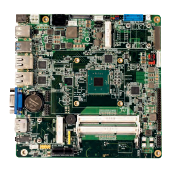
Page 9: Introduction
With smaller board size and lower height keep-out zones, the conga-IA3 SBC provides manufacturers and enthusiasts with the opportunity to design compact systems for space restricted areas. With appropriate I/O shield, the same conga-IA3 SBC can be used in either a Thin Mini-ITX or a Mini-ITX design. -
Page 10: Options Information
1.2.2 Optional Accessories/Cables Accessories Part No. Description conga-IA30/CSP 052351 Passive cooling solution with Thin Mini-ITX height (for conga-IA3) conga-IA30/Retention Frame 052355 Retention frame for conga-IA3 standard cooling conga-IA30/IO Bracket Standard Size 052356 IO shield for conga-IA3 with Mini-ITX height conga-IA30/IO Bracket Thin Size... - Page 11 30cm SATA power cable with 2x15 pin female connectors. SATA III cable (straight/straight) 48000029 30cm SATA III data cable with straight/straight connectors SATA III cable (straight/right-angled) 48000030 30cm SATA III data cable with straight/right-angled connectors Copyright © 2015 congatec AG IA30m10 11/82...
-
Page 12: Specification
1x optional SBM power Other Features Thermal and voltage monitoring CMOS Battery Beeper congatec Standard BIOS (also possible to boot from an external BIOS by triggering the BIOS_DISABLE# signal on the feature connector) Copyright © 2015 congatec AG IA30m10 12/82... -
Page 13: Supported Operating Systems
The conga-IA3 supports only DDR3L memory modules and the memory modules in the sockets must be symmetrical - that is, same raw cards and same memory sizes. This is because the Bay Trail SoC on the conga-IA3 does not support mixed raw cards or same raw cards with mixed memory sizes. -
Page 14: Mechanical Dimensions
Operation: 0° to 60°C Storage: -20° to +80°C Humidity Operation: 10% to 90% Storage: 5% to 95% Note The above operating temperatures must be strictly adhered to at all times. Humidity specifications are for non-condensing conditions. Copyright © 2015 congatec AG IA30m10 14/82... -
Page 15: Block Diagram
HD Audio ALC888S Internal speaker Power IN External I/O Internal I/O Audio OUT/MIC The mSATA/mPCIe connector supports both mPCIe and mSATA devices. The devices are detected automatically. Located at the bottom side. Optional feature. Copyright © 2015 congatec AG IA30m10 15/82... -
Page 16: Cooling Solution
Nonetheless, all electronics contain semiconductor devices which have operating temperature ranges that should be adhered to. This means that for reliable operation, the thermal design of the conga-IA3 must be carefully considered. For this reason, it is imperative to provide sufficient air flow to each of the components, to ensure the specified operating temperature of the conga-IA3 is maintained. -
Page 17: Cooling Installation
Caution congatec cooling solutions have been specifically designed for use within commercial temperature ranges (0° to 60°C) only. It is the responsibility of the end user to design an optimized thermal solution that meets the needs of their application within the industrial environmental conditions it is required to operate in. -
Page 18: Heatspreader
DIN/IS0 specifications. Caution When using the heatspreader in a high shock and/or vibration environment, congatec recommends the use of a thread-locking fluid on the cooling solution screws to ensure the above mentioned torque specification is maintained. Copyright © 2015 congatec AG... -
Page 19: Connector Description
Connector Description Power Supply You can power the conga-IA3 SBC with a 12V-24V laptop type DC power supply (on connector X43) or a 4 pin internal power supply (on connector X44). Additionally, the SBC offers an optional SBM power connector (only BOM option). When this connector (X45) is populated, you can power the SBC with it. -
Page 20: Power Supply (Internal Connector)
Caution The absolute maximum rating of the input voltage is 36 volts. Do not exceed this rating or expose the conga-IA3 to the absolute maximum voltage for a prolonged time. Doing so may damage the system or affect system reliability. -
Page 21: Optional Sbm3 Signal Connector
Caution The absolute maximum rating of the input voltage is 36 volts. Do not exceed this rating or expose the conga-IA3 to the absolute maximum voltage for a prolonged time. Doing so may damage the system or affect system reliability. -
Page 22: Pwr_Ok Signal
Power Status LEDs The conga-IA3 provides two LED signals (FP_LED1 and P_LED2) on pins 2 and 4 of the front panel connector X38. The signals indicate the different power states of the conga-IA3. Possible states and corresponding activity of the LEDs are shown below:... -
Page 23: Cmos Battery/Rtc
Rear Audio Connectors The conga-IA3 has a high definition audio codec (Realtek ALC888S) mounted on it. The front channel line output signals and the MIC input signals are routed to connector X48 (audio OUT/MIC) on the rear side. The drivers for this codec can be found in the software section under conga-IA3 on the congatec website at www.congatec.com... -
Page 24: Internal Audio Connectors
X48: 6 Pin, Single Audio Jack - black color 5.3.2 Internal Audio Connectors The conga-IA3 provides the stereo speaker, digital microphone/SPDIF and front panel HD audio connectors internally. 5.3.2.1 Stereo Speaker Header The first analog line input channels (left and right) of the Realtek ALC888S HDA audio codec are routed via a TPA2012D2 amplifier to internal stereo speaker - connector X19. -
Page 25: Digital Microphone/Spdif
2nd Analog Line Input - Right Channel (Headphone) Pin 10 GND_HDA Audio Ground SENSE_B Jack Detection Pin 2 No pin Pin 1 LINE2_L 2nd Analog Line Input - Left Channel (Headphone) GND_HDA Audio Ground Copyright © 2015 congatec AG IA30m10 25/82... -
Page 26: Communication Bus
Communication Bus The conga-IA3 supports both SMBus and I2C compliant devices. 5.4.1 SMBus The SMBus signals are available in different locations on the conga-IA3, including the feature connector (X34) described in section 6.13 of this document. 5.4.2 I²C Bus The congatec Board controller provides I²C signals. These signals are available in different locations on the conga-IA3, including the feature connector (X34) described in section 6.13 of this document. -
Page 27: Universal Serial Bus (Usb)
Rear USB Connectors The conga-IA3 offers a total of four USB ports on the rear side - two USB 2.0 ports on connector X14 and two USB 3.0 ports on connector X15. The USB 2.0 signals on connector X14 are routed directly from the SoC's USB ports 2 and 3. The USB 3.0 signals on connector X15 are routed from the SoC's USB Superspeed and USB port 0 signals via a USB 3.0 hub. -
Page 28: Internal Usb Connectors
Internal USB Connectors The conga-IA3 offers 4 USB ports internally - two USB 2.0 ports on connector X12 and two USB 3.0 ports on connector X60. The USB 2.0 signals on connector X12 are routed from the SoC's USB port 1 via a USB 2.0 hub. The USB 3.0 signals on connector X60 are routed from the SoC's USB Superspeed and USB port 0 signals via a USB 3.0 hub. -
Page 29: Ethernet 10/100/1000
Ethernet 10/100/1000 The conga-IA3 provides two Gigabit Ethernet ports (connectors X57 and X58) on the rear side. The two Gigabit Ethernet interfaces are supported via the Intel Gigabit Ethernet controller i211. These interfaces do not support the Intel AMT. -
Page 30: Sata Interfaces
Standard SATA Ports The conga-IA3 provides two SATA ports. The SATA ports are routed to connectors CN1/CN2 and support data rates up to 3GB/s. The SATA LED on the front panel connector (X38) is lit when there is activity on any of the SATA interfaces. -
Page 31: Sata Power
Mini SATA The mini SATA connector X6 on the conga-IA3 is used to connect mSATA devices. This connector also supports mini PCIe devices. When an mSATA or mPCIe device is connected to X6, the conga-IA3 automatically detects the type of device that is attached. - Page 32 X6: 0.8mm Pitch, 52 Pos. Mini PCI Socket Note * For card presence detection, pin 21 of the mSATA card must be terminated to ground. For card type recognition, pin 43 of the mSATA card must be unconnected. Copyright © 2015 congatec AG IA30m10 32/82...
-
Page 33: Display Interfaces
The conga-IA3 supports dual simultaneous displays - one Digital Display Interface and one embedded Display or LVDS interface. 5.8.1 Display Port Interface DP++ The conga-IA3 SBC has one DP++ connector (X26) located at the rear I/O panel. The display port supports the connection of DP, HDMI and DVI displays. Connectors X26 Pinout Description. - Page 34 Mating Connector: Possible mating connectors for X32 are ACES 88441-40 and ACES 50204-40. Note congatec offers cables and adapter for the LVDS interface (see section 1.2.2 “Optional Accessories/Cables”). For more information, contact congatec technical solution department. Copyright © 2015 congatec AG...
-
Page 35: Embedded Display Port (Edp)
Embedded Display Port (eDP) The conga-IA3 provides eDP interface on connector X28 - a standard 40 pin DisplayPort connector. The eDP signals are sourced from the SoC's eDP stream via a multiplexer. Depending on the BIOS setup, the multiplexer routes the eDP stream either directly to the eDP connector X28 on the bottom side of the SBC or to the LVDS connector X32 (top side) via an eDP to LVDS bridge. -
Page 36: Backlight Power Connector
5.8.3.1 Backlight Power Connector The conga-IA3 provides backlight power on connector X31. The power budget of BKLT_PWR (pins 3 and 4) is limited to 1.5 amps. Connector X31 Pinout Description Backlight Power - Connector X31... -
Page 37: Backlight/Panel Power Selection
Backlight/Panel Power Selection The conga-IA3 supports different voltages for the panel and backlight. With jumper X29, you can set the panel voltage to 3,3V, 5V or 12V. With jumper X30, you can set the backlight voltage to 5V or 12V. -
Page 38: Monitor Off Connector
X51: 2.54mm, 2 Pos. Molex Connector. PCI Express The conga-IA3 provides 3 PCIe interfaces - a x1 PCIe slot on connector X9, a half-size mini PCIe (mPCIe) slot on connector X10 and a full size mini PCIe/mini SATA slot on connector X6. Th 5.9.1... -
Page 39: Mini Pcie (Half Size)
Mini PCIe (Half Size) The conga-IA3 is equipped with a PCI Express Mini Card socket. PCI Express Mini Card is a unique small size form factor optimized for mobile computing platforms equipped with communication applications. The small footprint connector can be implemented on SBCs, providing the ability to insert different removable PCI Express Mini Cards. - Page 40 Pull down resistor (1M) N.C. W_DISABLE# PERST# PERn0 +3.3Vaux PERp0 +1.5V SMB_CLK PETn0 SMB_DATA PETp0 USB_D- USB_D+ +3.3Vaux +3.3Vaux mSATA_mPCIe_detect CL_CLK CL_DATA +1.5V CL_RST# N.C. +3.3Vaux Connector Type X10: PCIe Mini Card Socket Copyright © 2015 congatec AG IA30m10 40/82...
-
Page 41: Mini Pcie (Full Size)
Mini PCIe (Full Size) The conga-IA3 offers an mPCIe slot on connector X6. This connector supports both mPCIe and mSATA devices. The PCIe signals are routed from the SoC's PCIe lane 0 to connector X6 (mPCIe/mSATA slot) via two multiplexers. The first multiplexer switches the PCIe signals between the x1 PCIe slot (connector X9) and the mPCIe/mSATA slot (connector X6). -
Page 42: Pci Express Routing
X6 (mPCIe/mSATA). If you intend to use connector X9 , do not insert any mini PCIe device into connector X6. Mini PCIe Slot PCIe Lane 1 USB Signals Copyright © 2015 congatec AG IA30m10 42/82... -
Page 43: Additional Features
Front Panel Connector The conga-IA3 SBC supports front panel features such as power button, status LEDs and reset button via connector X38 - a 10-pin internal header. This connector offers one power supply pin (3.3V). The signals FP_LED+ and FP_LED- communicates the system states to two LEDs connected to this header. -
Page 44: Case Open Intrusion Connector
Trusted Platform Module – TPM (Optional) The conga-IA3 SBC can optionally be equipped with a TPM 1.2 compliant security chip. The TPM security chip is connected to the LPC bus provided by the integrated Intel Chipset. The basic TPM chip initialization is performed by the SBC’s UEFI Boot firmware. -
Page 45: Gpis
Serial Ports (COM) The Super IO controller on the conga-IA3 provides two fully featured RS-232 compliant UART interfaces (COM 0 and 1). The COM 1 interface can be optionally used as ccTALK compliant interface. The COM ports can drive up to 115 kbit/s at a maximum cable length of 15 m. -
Page 46: Gpos
CPU/System Fan Connector & Power Configuration The conga-IA3 supports the connection of 5V or 12V cooling fans. The signals of the CPU and system fans are routed to 4-pin connectors X35 and X37 respectively. Use jumper X33 to select the CPU fan voltage and jumper X36 to select the system fan voltage. -
Page 47: Oem Bios Customization
OEM POST Logo This feature allows system designers to replace the congatec POST logo displayed in the upper left corner of the screen during BIOS POST with their own BIOS POST logo. Use the congatec system utility CGUTIL 1.5.4 or later to replace/add the OEM POST logo. -
Page 48: Oem Bios Code/Data
OEM BIOS Code/Data With the congatec embedded BIOS, it is possible for system designers to add their own code to the BIOS POST process. The congatec Embedded BIOS first calls the OEM code before handing over control to the OS loader. -
Page 49: Api Support (Cgos)
The architecture of the CGOS API driver provides the ability to write application software that runs unmodified on all congatec CPU modules. All the hardware related code is contained within the congatec embedded BIOS on the module. See section 1.1 of the CGOS API software developers guide, which is available on the congatec website . -
Page 50: Feature Connector
6.13 Feature Connector The conga-IA3 provides an internal 50 pol. 2mm pin header as feature connector. The pinout is described below: Feature Connector X34 Pinout Description Signal Signal +V5S LAD0 LAD1 LAD2 LAD3 LFRAME# SERIRQ# Feature Connector X34 LPC_CLK (25MHz) -
Page 51: Conga-Ia3 Mechanical Drawing
SPDIF/DMIC SATA1 SATA0 COM0 COM1 HALF-MINI CARD (30.00x26.80) FULL-MINI CARD Line OUT/ Display Port ++ width = 335mil width = 787mil width =1319mil 6.35 20.06 44.26 53.21 63.76 78.2 114.76 132.35 156.55 163.83 Copyright © 2015 congatec AG IA30m10 51/82... -
Page 52: Bios Setup Description
BIOS setup program. Setup Menu and Navigation The congatec BIOS setup screen is composed of the menu bar, left frame and right frame. The menu bar is shown below: Main... -
Page 53: Main Setup Screen
Serial Number No option Displays the serial number of the board. BC Firmware Revision No option Displays the firmware revision of the congatec board controller. MAC Address No option Displays the MAC address of the onboard Ethernet controller. MAC Address #2 No option Displays the MAC address of the second onboard Ethernet controller. -
Page 54: Advanced Setup
Thermal Configuration IDE Configuration Miscellaneous Configuration SCC Configuration PCI Subsystem Settings Network Stack CSM Configuration Trusted Computing Platform Trust Technology Security Configuration Intel(R) I211 Gigabit Network #1 Intel(R) I211 Gigabit Network #2 Driver Health Copyright © 2015 congatec AG IA30m10 54/82... -
Page 55: Watchdog Submenu
Select the type of event that will be generated when timeout 2 is reached. ACPI Event Reset Power Button Event 3 Disabled Select the type of event that will be generated when timeout 3 is reached. ACPI Event Reset Power Button Copyright © 2015 congatec AG IA30m10 55/82... - Page 56 Note In ACPI mode, it is not possible for a “Watchdog ACPI Event” handler to directly restart or shutdown the OS. For this reason the congatec BIOS will do one of the following: For Shutdown: An over temperature notification is executed. This causes the OS to shut down in an orderly fashion.
-
Page 57: Graphics Submenu
Auto detection is performed by reading an EDID data set via the video I²C bus. WVGA 800x480 1x24 (01Bh) The number in brackets specifies the congatec internal number of the respective panel data set. Note: Customized EDID™ utilizes an OEM defined EDID™ data set stored in the BIOS flash device. -
Page 58: Hardware Health Monitoring Submenu
PWM Mode Minimum Fan Speed 0%, 10%, 20%, 30%, 40%, Select minimum/start fan speed to be set when the start temperature of the control slope is reached. 50%, 60%, 70%, 80%, 90%, 100% Copyright © 2015 congatec AG IA30m10 58/82... -
Page 59: Trusted Computing Submenu
IRQ15 Reserve Legacy Interrupt 2 Same as Reserve Legacy Same as Reserve Legacy Interrupt 1 Interrupt 1 Reserve Legacy Interrupt 3 Same as Reserve Legacy Same as Reserve Legacy Interrupt 1 Interrupt 1 Copyright © 2015 congatec AG IA30m10 59/82... -
Page 60: Acpi Submenu
Logical Device Settings No option Show current logical device settings Possible Use Automatic Settings Serial Port 1 configurations options IO=3F8; IRQ=3,4,5,7,9,10,11, 12; DMA; IO=2F8; IRQ=3,4,5,7,9,10,11, 12; DMA; IO=3F8; IRQ=3,4,5,7,9,10,11, 12; DMA; IO=3E8; IRQ=3,4,5,7,9,10,11, 12; DMA; Copyright © 2015 congatec AG IA30m10 60/82... -
Page 61: Serial Port 2 Submenu
ISCT Sleep Duration Value Duration in Seconds ISCT Sleep Duration in seconds. Format ISCT RF Kill Switch Type Software Select ISCT RF Kill Switch Type Hardware ISCT RTC Timer Support Disabled Enable ISCT RTC Timer Enabled Copyright © 2015 congatec AG IA30m10 61/82... -
Page 62: Serial Port Console Redirection Submenu
With recorder mode enabled, only text output will be sent over the terminal. This is helpful to capture and Enabled record terminal data. Resolution 100x31 Disabled Enable or disable extended terminal resolution. Enabled Legacy OS Redirection 80x24 Number of rows and columns supported for legacy OS redirection. Resolution 80x25 Copyright © 2015 congatec AG IA30m10 62/82... -
Page 63: Console Redirection Settings Out-Of-Band Management
OS. Intel Virtualization Technology Disabled Enable or disable support for the Intel virtualization technology. Enabled Power Technology Disable Configure the power technology schema for the CPU Energy Efficient Custom Copyright © 2015 congatec AG IA30m10 63/82... -
Page 64: Socket 0 Cpu Information Submenu
Disabled Enable or disable CPU state Report to Operating System. Enabled Max CPU C state Maximal CPU C state supported by the CPU SOix Disabled Enable or disable CPU SOix state support Enabled Copyright © 2015 congatec AG IA30m10 64/82... -
Page 65: Thermal Configuration Submenu
90 C 87 C 85 C 79 C 71 C 63 C 55 C 47 C 39 C 31 C 23 C 15 C Note The conga-IA3 does not support active trip point. Copyright © 2015 congatec AG IA30m10 65/82... -
Page 66: Ide Configuration Submenu
Enable or disable the high precision event timer. Disabled Boot Timer with HPET Timer Enabled Allow boot timer calculation with the high precision event timer. Disabled PCI Express Dynamic Clock Enabled Enable dynamic clock gating. Disabled Gating Copyright © 2015 congatec AG IA30m10 66/82... -
Page 67: Scc Configuration Submenu
Enable or Disable 64bits capable Devices to be Decoded in Above 4G Address Space (Only if system supports 64 bits Enabled PCI Decoding) SR-IOV Support Disabled If system has SR-IOV capable PCIe Devices, this option enables or disables Single Root IO Virtualization support Enabled Copyright © 2015 congatec AG IA30m10 67/82... -
Page 68: Pci Express Setting Submenu
On non-PCI Express aware operating systems some devices may not be re-initialized correctly after S3. Setting this node Disabled to Enabled restores PCI Express configuration on S3 resume. Warning: Enabling this may cause issues with other hardware after S3 resume. Copyright © 2015 congatec AG IA30m10 68/82... -
Page 69: Pci Express Gen 2 Settings Submenu
Hardware Autonomous If supported by hardware and set to 'Disabled', this will disable the hardware's ability to change link speed except speed Speed Enabled rate reduction for the purpose of correcting unstable link operation. Copyright © 2015 congatec AG IA30m10 69/82... -
Page 70: Network Stack
Controls the execution of UEFI and legacy Video option ROMs UEFI only Legacy only Other PCI Devices UEFI only Controls the execution of UEFI and legacy option ROMs for any other PCI device different to Network, Video and Storage. Legacy only Copyright © 2015 congatec AG IA30m10 70/82... -
Page 71: Sdio Submenu
100ms for a root port or derived from the hub descriptor for a hub port. Device Power -Up Delay 0-40 Actual power-up delay value in seconds. Value Default : 5 8.4.23 Platform Trust Technology Feature Options Description fTPM Disabled Enable Trusted Platform Module support. Enabled Copyright © 2015 congatec AG IA30m10 71/82... -
Page 72: Security Configuration
Displays the PCI Device ID of the Ethernet controller. Bus:Device:Function No option Displays the PCI Bus:Device:Function number of the Ethernet controller. Link Status No option Displays the Link Status. MAC Address No option Displays the MAC Address. Copyright © 2015 congatec AG IA30m10 72/82... -
Page 73: Nic Configuration Submenu
Maximum value of TOLUD Dynamic assignment would adjust TOLUD automatically based on largest 2.5 GB, 2.75 GB, 3 GB, MMIO length of installed graphic controller. Aperture Size 128MB Select Aperture Size 256MB 512MB Copyright © 2015 congatec AG IA30m10 73/82... -
Page 74: South Bridge Submenu
Enable Azalia Docking support. Disable Azalia PME Enable Enabled Enable Azalia PME support. Disabled Azalia HDMI Codec Enabled Enable Azalia HDMI Codec Disabled HDMI Port B Enabled Enable HDMI Port B Audio. Disabled Copyright © 2015 congatec AG IA30m10 74/82... -
Page 75: Usb Submenu
Enabled USB Port 0 Disabled Enable Port 0 Enabled USB Port 1 Disabled Enable Port 1 Enabled USB Port 2 Disabled Enable Port 2 Enabled USB Port 3 Disabled Enable Port 3 Enabled Copyright © 2015 congatec AG IA30m10 75/82... -
Page 76: Pci Express Configuration Submenu
Bootup NumLock State Select the keyboard numlock state. Quiet Boot Disabled Disabled displays normal POST diagnostic messages. Enabled Enabled displays OEM logo instead of POST messages. Note: The default OEM logo is a dark screen. Copyright © 2015 congatec AG IA30m10 76/82... - Page 77 Note 1. The term ‘AC power loss’ stands for the state when the module looses the standby voltage on the 5V_SB pins. On congatec modules, the standby voltage is continuously monitored after the system is turned off. If within 30 seconds the standby voltage is no longer detected, then this is considered an AC power loss condition.
-
Page 78: Security Setup
List of all boot devices Select device to leave setup menu and boot from the selected device. currently detected Only visible and active if Boot Priority Selection setup node is set to “Device Based”. Copyright © 2015 congatec AG IA30m10 78/82... -
Page 79: Additional Bios Features
Additional BIOS Features The conga-IA3 uses a congatec/AMI AptioEFI that is stored in an onboard Flash Rom chip and can be updated using the congatec System Utility (version 1.5.0 and later), which is available in a DOS based command line, Win32 command line, Win32 GUI, and Linux version. -
Page 80: Industry Specifications
Industry Specifications The list below provides links to industry specifications that apply to congatec AG modules. Specification Link Low Pin Count Interface Specification, Revision 1.0 (LPC) http://developer.intel.com/design/chipsets/industry/lpc.htm Universal Serial Bus (USB) Specification, Revision 2.0 http://www.usb.org/home PCI Specification, Revision 2.3 http://www.pcisig.com/specifications Serial ATA Specification, Revision 3.0... - Page 81 Copyright © 2015 congatec AG IA30m10 81/82...
- Page 82 Copyright © 2015 congatec AG IA30m10 82/82...
Need help?
Do you have a question about the conga-IA3 and is the answer not in the manual?
Questions and answers