
Subscribe to Our Youtube Channel
Related Manuals for Congatec conga-HPC/EVAL-Client


Summary of Contents for Congatec conga-HPC/EVAL-Client
- Page 1 Detailed description of the congatec COM-HPC® Client Module Size A, B, C evaluation carrier board User’s Guide Revision 0.3 (Preliminary) Copyright © 2021 congatec GmbH GEVAm03 1/65...
- Page 2 Preliminary release 2021-04-14 • Updated operating and storage temperature in section 3.1 “Feature List” and 3.3 “Environmental Specifications” • 2021-07-26 Added Software License Information to preface section • Updated section 3.1 “Feature List” Copyright © 2021 congatec GmbH GEVAm03 2/65...
- Page 3 DECLINE ALL LIABILITY for damages, direct or indirect, that result from the use of this software. OEM/ CGUTL BIOS BIOS/UEFI modified by customer via the congatec System Utility (CGUTL) is subject to the same license as the BIOS/UEFI it is based on. You can find the specific details at https://www.congatec.com/en/licenses/.
- Page 4 Copyright © 2021, congatec GmbH. All rights reserved. All text, pictures and graphics are protected by copyrights. No copying is permitted without written permission from congatec GmbH. congatec GmbH has made every attempt to ensure that the information in this document is accurate yet the information contained within is supplied “as-is”.
- Page 5 Notes call attention to important information that should be observed. Connector Type Describes the connector that must be used with the congatec evaluation carrier board, not the connector found on the congatec evaluation carrier board. Link to connector layout diagram This link icon is located in the top left corner of each page.
- Page 6 (c) arising from course of performance, course of dealing, or usage of trade. congatec GmbH shall in no event be liable to the end user for collateral or consequential damages of any kind. congatec shall not otherwise be liable for loss, damage or expense directly or indirectly arising from the use of the product or from any other cause.
- Page 7 Gigabit Ethernet LVDS Low Voltage Differential Signaling HBR3 High Bit Rate 3 Display Data Channel GPIO General Purpose Input/Output Embedded DisplayPort LVDS Low Voltage Differential Signaling Not connected Not available To be determined Copyright © 2021 congatec GmbH GEVAm03 7/65...
-
Page 8: Table Of Contents
I2C I/O Expander Pin Header ..........59 4.4.2.4 Flat Panel and Backlight Voltage Selection ......36 4.24 CSI Port 0 ................. 60 4.4.2.5 Flat Panel Configuration Data ..........37 4.25 CSI Port 1 ................. 61 Copyright © 2021 congatec GmbH GEVAm03 8/65... - Page 9 5.1.1 Power ..................62 5.1.2 Reset ..................62 5.1.3 LID .................... 62 5.1.4 Sleep ..................63 Ground Test Points ..............63 Debug Display ................. 63 Debug LEDs ................64 Mechanical Dimensions ............65 Copyright © 2021 congatec GmbH GEVAm03 9/65...
- Page 10 X38 - NBASET1_SDP Header Pinout ........40 Table 68 X41 - CSI Port 1 Pinout ............61 Table 34 X54 - Ethernet Mezzanine Card Connector Pinout ....40 Table 35 X49 - Audio Jack Pinout ............42 Copyright © 2021 congatec GmbH GEVAm03 10/65...
-
Page 11: Introduction
Soundwire 0 / 1 I2S / 2 Soundwire 0 / 1 Asynchronous Serial Ports 0 / 2 1 / 2 Connector 1 / 1 1 / 1 0 / 1 1 / 1 Copyright © 2021 congatec GmbH GEVAm03 11/65... -
Page 12: Conga-Hpc/Eval-Client
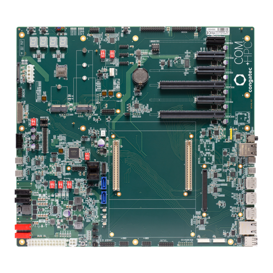
The various features and capabilities offered by the conga-HPC/EVAL-Client carrier board makes it ideal for the integration of Client Module Sizes A, B, and C. -
Page 13: Connector Layout
M2 CARD (22.00x60.00) JP10 M2 CARD (30.00x42.00) M2 CARD KEY ID 'E' 2x PCIe x1/USB2.0/I2C/SDIO/UART/PCM (22.00x30.00/30.00x30.00) M2 CARD (22.00x42.00) (KEY ID. 'E') (KEY ID. 'B') (KEY ID. 'B') JP13 JP12 SW16 JP14 JP11 Copyright © 2021 congatec GmbH GEVAm03 13/65... -
Page 14: Specifications
304.8 x 330.2 mm (approx. 12 x 13 inches) Order Information PN 065600 conga-HPC/EVAL-Client Note The module must also support the features for them to function. Refer to the module’s user’s guide for information about supported features. Copyright © 2021 congatec GmbH GEVAm03 14/65... -
Page 15: Mechanical Dimensions
Storage: 5% to 95% Note The above operating temperatures must be strictly adhered to at all times. The maximum operating temperature refers to any measurable spot on the modules surface. Humidity specifications are for non-condensing conditions. Copyright © 2021 congatec GmbH GEVAm03 15/65... -
Page 16: Connectors And Features
VCC_5V_SBY SNDW_DMIC_DAT0 USB67_OC# DDI0_PAIR1- DDI1_PAIR1- USB45_OC# DDI0_DDC_AUX_SEL DDI0_PAIR1+ DDI1_PAIR1+ USB23_OC# DDI1_DDC_AUX_SEL USB01_OC# DDI0_HPD DDI0_PAIR2- DDI1_PAIR2- SML1_CLK DDI1_HPD DDI0_PAIR2+ DDI1_PAIR2+ SML1_DAT eDP_HPD PMCALERT# eDP_VDD_EN DDI0_PAIR3- DDI1_PAIR3- SML0_CLK eDP_BKLT_EN DDI0_PAIR3+ DDI1_PAIR3+ SML0_DAT eDP_BKLTCTL USB_PD_ALERT# AC_PRESENT Copyright © 2021 congatec GmbH GEVAm03 16/65... - Page 17 PCIe00_TX- PCIe08_TX- PCIe08_RX+ PCIe00_RX- PCIe00_TX+ PCIe08_TX+ PCIe00_RX+ PCIe09_RX- PCIe01_TX- PCIe09_TX- PCIe09_RX+ PCIe01_RX- PCIe01_TX+ PCIe09_TX+ PCIe01_RX+ PCIe10_RX- PCIe02_TX- PCIe10_TX- PCIe10_RX+ PCIe02_RX- PCIe02_TX+ PCIe10_TX+ PCIe02_RX+ PCIe11_RX- PCIe03_TX- PCIe11_TX- PCIe11_RX+ PCIe03_RX- PCIe03_TX+ PCIe11_TX+ PCIe03_RX+ PCIe12_RX- PCIe04_TX- Copyright © 2021 congatec GmbH GEVAm03 17/65...
- Page 18 GP_SPI_MOSI I2C0_CLK GPIO_06 GP_SPI_MISO I2C0_DAT NBASET0_MDI3- GPIO_07 GP_SPI_CS0# I2C0_ALERT# NBASET0_MDI3+ GPIO_08 GP_SPI_CS1# I2C1_CLK GPIO_09 GP_SPI_CS2# I2C1_DAT NBASET0_LINK_MAX# GPIO_10 GP_SPI_CS3# NBASET0_SDP NBASET0_LINK_MID# GPIO_11 GP_SPI_CLK NBASET0_CTREF NBASET0_LINK_ACT# A100 TYPE0 B100 GP_SPI_ALERT# C100 TYPE1 D100 TYPE2 Copyright © 2021 congatec GmbH GEVAm03 18/65...
-
Page 19: Table 5 Connector P2 (X4) Pinout
PCIe41_RX+ PCIe34_RX- PCIe42_TX- PCIe34_TX- PCIe34_RX+ PCIe42_RX- PCIe42_TX+ PCIe34_TX+ PCIe42_RX+ PCIe35_RX- PCIe43_TX- PCIe35_TX- PCIe35_RX+ PCIe43_RX- PCIe43_TX+ PCIe35_TX+ PCIe43_RX+ PCIe36_RX- PCIe44_TX- PCIe36_TX- PCIe36_RX+ PCIe44_RX- PCIe44_TX+ PCIe36_TX+ PCIe44_RX+ PCIe37_RX- PCIe45_TX- PCIe37_TX- PCIe37_RX+ PCIe45_RX- PCIe45_TX+ PCIe37_TX+ PCIe45_RX+ Copyright © 2021 congatec GmbH GEVAm03 19/65... - Page 20 RSVD RSVD RSVD RSVD RSVD RSVD RSVD NBASET1_MDI0- CSI1_RX0- RSVD NBASET1_MDI0+ CSI0_RX0- CSI1_RX0+ RSVD CSI0_RX0+ RSVD NBASET1_MDI1- CSI1_RX1- RSVD NBASET1_MDI1+ CSI0_RX1- CSI1_RX1+ RSVD CSI0_RX1+ RSVD NBASET1_MDI2- CSI1_RX2- NBASET1_CTREF NBASET1_MDI2+ CSI0_RX2- CSI1_RX2+ NBASET1_SDP CSI0_RX2+ Copyright © 2021 congatec GmbH GEVAm03 20/65...
- Page 21 PCIe_REFCLK2- PCIe_REFCLKIN0- PCIe_REFCLK1- PCIe_REFCLK2+ RSVD PCIe_REFCLKIN0+ PCIe_REFCLK1+ RSVD RSVD PCIe_REFCLKIN1- PCIe_CLKREQ1# ETH0-1_PRSNT# ETH0-1_I2C_CLK PCIe_REFCLKIN1+ PCIe_CLKREQ2# ETH0-1_PHY_RST# ETH0-1_I2C_DAT PCIe_CLKREQ_OUT0# ETH0_SDP ETH0-1_PHY_INT# ETH0-1_MDIO_CLK PCIe_CLKREQ_OUT1# ETH1_SDP ETH0-1_INT# ETH0-1_MDIO_DAT E100 PCIe_PERST_IN0# F100 PCIe_PERST_IN1# G100 PCIe_WAKE_OUT0# H100 PCIe_WAKE_OUT1# Copyright © 2021 congatec GmbH GEVAm03 21/65...
-
Page 22: Power Supply Connectors
4.1.1 ATX Power Connectors The conga-HPC/EVAL-Client provides a standard 24-pin ATX power connector (X63) and 4-pin ATX12V power connector (X64) for an ATX power supply. Power must be supplied to both connectors. With an ATX power supply, the COM-HPC ®... -
Page 23: Table 7 Jp13 - Atx 5V Standby Settings
Power supply +5 VDC +3.3V Power supply +3.3 VDC Power ground Connector Type X63: Standard 24-pin ATX Power connector Note The -12 V power output of the ATX power supply is not used. Copyright © 2021 congatec GmbH GEVAm03 23/65... -
Page 24: Dc Banana Jacks
DC Banana Jacks The conga-HPC/EVAL-Client provides four banana jacks (X67, X68, X69, X70) for a DC power supply to power both the module and the voltage regulators on the carrier board. The maximum power rating per banana jack is 16 A. Depending on the power requirements of the system, use one or two pairs of banana jacks to power the system. -
Page 25: Power States Leds
4.1.3 Power States LEDs The LEDs D74-D75 and D77-D81 indicate the different power states of the conga-HPC/EVAL-Client as described in the table below. Table 12 Power LEDs Status LED Status Description D74 D75 D79 D80 D81 D77 D78 No power applied. -
Page 26: Power-Up Control
Note If the conga-HPC/EVAL-Client detects an incompatible module pinout, an onboard logic prevents the board from powering up the whole system by controlling the PS_ON# signal of the ATX power supply. Only works in ATX mode. AT mode does not support this feature. -
Page 27: Cmos Battery Holder
JP12: 2.54 mm, 2-pin jumper CMOS Battery Holder The conga-HPC/EVAL-Client provides battery holder M18 for a CR2032 battery. The battery supplies power to the RTC and CMOS memory. Warning Danger of explosion if battery is incorrectly replaced. Replace only with the same or equivalent type recommended by the manufacturer. -
Page 28: Pcie Connectors
Note The PCIe lanes [8:11] on connector X8 are routed through a PCIe Gen4 compatible retimer on the conga-HPC/EVAL-Client. It currently supports 1 x4, 1 x1, and 1 x2 PCIe Bifucration. If other PCIe Bifurcation options are required, contact congatec technical support. -
Page 29: Pcie Bmc Slot
Connector Type JP1: 2.54 mm, 2-pin jumper 4.3.3 PCIe BMC Slot The conga-HPC/EVAL-Client provides a standard PCIe x1 slot (X9) dedicated for a Board Management Controller (BMC) card. Connector Type X9: PCIe BMC Card Copyright © 2021 congatec GmbH GEVAm03... -
Page 30: M.2 Key B + Micro-Sim Card Slot
M.2 Key B + micro-SIM Card Slot The conga-HPC/EVAL-Client provides a standard M.2 Key B socket X12. The socket is routed to the module’s PCIe lanes [12:13] and USB Port 6. LED D7 lights red when there is activity on this socket. -
Page 31: M.2 Key E
M.2 Key E The conga-HPC/EVAL-Client provides a standard M.2 Key E socket X15. The socket is routed to the module’s PCIe lanes [14:15], USB Port 7, and UART1 port. LED D9 is connected to the LED2# signal of the M.2 Key E socket. LED D10 is connected to the LED1# signal of the M.2 Key E socket. -
Page 32: Table 21 Jp1 - Pcie Clock Request Signal Settings
Deactivate UART (default) Activate UART Note The UART signals are shared with the UART1 signals on connector X43 and X55. For more information, see section 4.14.2.4 “Module Serial Port 1” and section 4.17 “Feature Connector”. Copyright © 2021 congatec GmbH GEVAm03 32/65... -
Page 33: Display Interfaces
Display Interfaces 4.4.1 DP++ The conga-HPC/EVAL-Client provides three DP++ ports (X26, X27, and X28). The three DP++ ports are routed through a DisplayPort re-driver to support HBR3 data rate (up to 12 Gbps). X26, X27, X28 Connector Type X26, X27, X28: Standard DP plug 4.4.2... -
Page 34: Lvds
LVDS0_D2- LVDS0_CLK- LVDS0_CLK+ LVDS0_D3+ LVDS0_D3- LVDS1_D0- LVDS1_D0+ LVDS1_D1- LVDS1_D1+ LVDS1_D2- LVDS1_D2+ LVDS1_CLK+ LVDS1_CLK LVDS1_D3+ LVDS1_D3- Connector Type X29: 2 mm, 2x17 pin female connector Note For LVDS functionality, set DIP SW4.1 to ON. Copyright © 2021 congatec GmbH GEVAm03 34/65... -
Page 35: Edp
N.C. eDP]_AUX+ N.C. eDP_AUX- BKLT_PWR PANEL_PWR BKLT_PWR PANEL_PWR BKLT_PWR PANEL_PWR N.C. Connector Type X30: 0.5 mm, 40 Pos. (ACES 50203-04001-001 or compatible) Note For eDP functionality, set DIP SW4.1 to OFF. Copyright © 2021 congatec GmbH GEVAm03 35/65... -
Page 36: Edp Panel And Backlight Power Supply
X31: 2.54 mm, 2x5 pin female connector 4.4.2.4 Flat Panel and Backlight Voltage Selection The conga-HPC/EVAL-Client supports different voltages for the panel and backlight. Follow the descriptions in the tables below to set the panel and backlight voltages. Table 27... -
Page 37: Flat Panel Configuration Data
• USB 2.0 @ M.2 Key E – port 7 on connector X15 4.5.1 USB4 Type-C Ports The conga-HPC/EVAL-Client provides four USB4 ports (X19, X20, X22, X23). For information about USB4, refer to the COM-HPC Specification. ® Connector Type X19, X20, X22, X23 X19, X20, X22, X23: USB Type-C plug Copyright ©... -
Page 38: Dual Stacked Usb 2.0 Type-A Ports
4.5.2 Dual Stacked USB 2.0 Type-A Ports The conga-HPC/EVAL-Client provides two USB 2.0 ports via a dual-stacked USB Type-A connector (X25). Each port provides up to 1.7 A. Connector Type X25: USB Type-A plug SATA The conga-HPC/EVAL-Client provides two standard SATA connectors (X32, X33): •... -
Page 39: Sata Power
X34: Standard 15-pin SATA power connector Ethernet Ports The conga-HPC/EVAL-Client provides RJ45 ethernet ports X37 and X39. The NBASE-T Ethernet Controller [0:1] Software-Definable Pins (SDP) NBASET[0:1]_SDP are provided on pin headers X36 and X38: • ETH0 port on connector X37 –... -
Page 40: Ethernet Mezzanine Card Connector
Ground Connector Type X37, X39: RJ45 plug X36, X38: 1.25 mm, 2-pin female connector Ethernet Mezzanine Card Connector The conga-HPC/EVAL-Client provides connector X54 for an Ethernet Mezzanine card. Table 34 X54 - Ethernet Mezzanine Card Connector Pinout Signal Pin Signal... - Page 41 C35 GND B36 GND C36 GND B37 GND C37 GND +V12S B38 +V12S C38 +V12S +V12S +V12S B39 +V12S C39 +V12S +V12S +V12S B40 +V12S C40 +V12S +V12S Connector Type X54: Ethernet Mezzanine Card Copyright © 2021 congatec GmbH GEVAm03 41/65...
-
Page 42: Audio Interfaces
® • DMIC signals on connector X48 4.9.1 Audio Jack (4-Pole) The conga-HPC/EVAL-Client features a 4-pole audio jack (X49) for a 3.5 mm CTIA standard plug. This audio jack is connected to an onboard SoundWire codec (Realtek ALC711). ® Table 35... -
Page 43: Dmic
The conga-HPC/EVAL-Client provides an EEPROM 24C32 on the 8-pin DIL socket U55 for test purposes during system development. This EEPROM is connected to the I2C0 bus and has the I²C address 0xAE. Use the I²C control commands implemented in the congatec CGOS API driver to access the EEPROM. -
Page 44: Spi Flash Socket
I2C1 Bus The conga-HPC/EVAL-Client provides the I2C1 signals on connector X50 and X60. For more information, see section section 4.9.2 “I²S/ SoundWire®” and section 4.20 “I2C1 Pin Header”. Connector Type U55: 2-wire 3.3 V Serial EEPROMS in 8-pin DIL package 4.11... -
Page 45: Table 38 Bios Select Options
Carrier BMC control device on Module Carrier BIOS on Carrier SAFS Note For the conga-HPC/EVAL-Client, the most common BSEL[2:0] settings are 111 and 110. Use DIP SW9.1 to switch between these two options. Copyright © 2021 congatec GmbH GEVAm03 45/65... -
Page 46: Intel Isp Adaptor-C2 Connector
4.12 Intel ISP Adaptor-C2 Connector The conga-HPC/EVAL-Client provides connector X53 for an Intel ISP Adaptor-C2. Table 39 X53 - Intel ISP Adaptor-C2 Connector Pinout Pin Signal Pin Signal BOOT_SPI_CS0# DEBUG_RST# VCC_BOOT_SPI SPI_CLK_ISP SPI_IO2_ISP SPI_IO3_ISP SPI_IO1_ISP SPI_IO0_ISP PLTRST# Use jumper JP8 to select the DEBUG_RST# trigger signal of the connector X53. -
Page 47: General Purpose Spi Port
CN2: 2.54 mm, 2x8 pin female connector 4.14 eSPI On the conga-HPC/EVAL-Client, the module’s eSPI interface is routed to a Super I/O controller (Nuvoton NCT6122D). The Super I/O controller provides the following interfaces: • One eSPI header (X44) • Two serial ports (X45 and X46) •... -
Page 48: Table 42 Sw6.1 - Super I/O Settings
Super IO key selection 88h SW5.3 Disables Super IO Port 80 control (default) Enables Super IO Port 80 control SW5.4 Enable Port 80 to UART Serial Output (default) Disable Port 80 to UART Serial Output Copyright © 2021 congatec GmbH GEVAm03 48/65... -
Page 49: Espi Header
• Module UART1 on connector X43 4.14.2.1 COM Port 0 Header The conga-HPC/EVAL-Client provides COM port 0 on connector X46 via the onboard Super I/O. The port supports RS-232, RS-422 and RS-485 I/O voltage levels. Copyright © 2021 congatec GmbH... -
Page 50: Table 46 Sw7 - Com Port 0 Transceiver Settings
250 kbps SLEW LIMITING (for EMI) SW8.2 RS-485/422 Termination disabled RS-485/422 Termination enabled Table 48 X46 - COM 0 Pinout Signals Signals DCD# RTS# CTS# DTR# +5V (750mA fuse) Connector Type X46: 2.54 mm, 2x5 pin female connector Copyright © 2021 congatec GmbH GEVAm03 50/65... -
Page 51: Com Port 1 Header
4.14.2.3 Module Serial Port 0 The conga-HPC/EVAL-Client provides the module’s serial port 0 (UART0) on header X42. UART0 is also connected to pins 19 and 21 of the feature connector X55. For more information, see section 4.17 “Feature Connector”. Table 50... -
Page 52: Module Serial Port 1
Module Serial Port 1 The conga-HPC/EVAL-Client provides the module’s serial port 1 (UART1) on header X43. UART1 is also connected to the M.2 key E slot X15 and feature connector X55. For more information, see section 4.3.5 “M.2 Key E” and section 4.17 “Feature Connector”. -
Page 53: System Fan Header
X43: 2.54 mm, 2x5 pin female connector JP5: 2.54 mm grid jumper 4.14.3 System Fan Header The conga-HPC/EVAL-Client provides a 3-pin fan connector X47 via the Super I/O controller. Table 54 X47 - SYS Fan Pinout Pin Signal +VDD (12V/5V) Sense Use jumper JP6 to set the fan’s supply voltage level. -
Page 54: Cpu Fan Header
Connector Type X62: 2.54 mm, 4-pin fan plug JP10: 2.54 mm grid jumper 4.16 Debug Header The conga-HPC/EVAL-Client provides pin header X57 for measuring or debugging PCIE_WAKE# and PLTRST# signals. Table 59 X57 - Debug Header Pinout Signal Signal PLTRST#... -
Page 55: Feature Connector
Module input for vendor specific module AC_PRESENT Driven hard low on Carrier if system AC power is not present. test mode(s). Power ground Power ground Connector Type X55: 2.54 mm, 2x13 pin female connector Copyright © 2021 congatec GmbH GEVAm03 55/65... -
Page 56: Gpio Pin Header
4.18 GPIO Pin Header The conga-HPC/EVAL-Client provides 12 GPIO pins on header X58. Table 61 X58 - GPIO Header Pinout Signal Signal +V3.3 standby (0.75 A fuse) +V3.3 main (0.75 A fuse) GPIO_00 GPIO_01 GPIO_02 GPIO_03 GPIO_04 GPIO_05 GPIO_06 GPIO_07... -
Page 57: I2C0 Pin Header
4.19 I2C0 Pin Header The conga-HPC/EVAL-Client provides I2C0 pins on header X59. I2C0 is defined to operate with 3.3 V. Table 62 X59 - I2C0 Pin Header Pinout Signal +V3.3 standby (0.75 A fuse) I2C0_DAT I2C0_CLK I2C0_ALERT# Connector Type X59: 2.54 mm, 5-pin female connector 4.20... -
Page 58: Smbus Pin Header
SMB_DAT SMB_CLK SMB_ALERT# Connector Type X61: 2.54 mm, 5-pin female connector 4.22 Front Panel Pin Header The conga-HPC/EVAL-Client provides front panel pins on header X56. Table 65 X56 - Front Panel Pin Header Pinout Signal Signal PWRBTN# RSTBTN# No pin Connector Type X56: 2.54 mm, 2x5 pin female connector... -
Page 59: I2C I/O Expander Pin Header
4.23 I2C I/O Expander Pin Header The conga-HPC/EVAL-Client provides eight I²C pins on header X52 via an I/O expander (TI PCA9554) . The I/O expander is connected to I2C0. Table 66 X52 - I2C Header Pinout Signal Signal I2C_IOE_B0 I2C_IOE_B1... -
Page 60: Csi Port 0
CSI0_I2C_CLK CSI0_I2C_DAT CSI0_ENA CSI0_MCLK Connector Type X40: 22-pin flexible flat cable, 0.5 mm pitch, 0.3 mm thickness (Bottom Contact) Note This connector will change in the mass production (MP) revision of the conga-HPC/EVAL-Client. Copyright © 2021 congatec GmbH GEVAm03 60/65... -
Page 61: Csi Port 1
CSI1_I2C_CLK CSI1_I2C_DAT CSI1_ENA CSI1_MCLK Connector Type X41: 22-pin flexible flat cable, 0.5 mm pitch, 0.3 mm thickness (Bottom Contact) Note This connector will change in the mass production (MP) revision of the conga-HPC/EVAL-Client. Copyright © 2021 congatec GmbH GEVAm03 61/65... -
Page 62: Additional Features
Additional Features Buttons The conga-HPC/EVAL-Client features power, reset, LID and sleep buttons. 5.1.1 Power When you press the power button SW11, it triggers the module’s PWRBTN# signal. The triggered event usually initiates a transition from one power state to another (for example, from S5 to S0). However, the system’s behavior depends on the ACPI settings of the Operating System. -
Page 63: Sleep
Operating System. SW14 Ground Test Points The conga-HPC/EVAL-Client provides 4 test points (M1-M4). These test points are connected to ground and they make it easier to connect oscilloscope probes or multimeter lines or both to ground during measurements. M1-M4 Debug Display The conga-HPC/EVAL-Client provides four 14-segment displays (D66-D69) for post code or debug information. -
Page 64: Debug Leds
Debug LEDs The conga-HPC/EVAL-Client provides eight LEDs (D47-D54) for post code or debug information in binary format. A list of the BIOS POST codes and associated POST test and initialization routines for congatec COM-HPC modules is available at www.congatec.com. ®... -
Page 65: Mechanical Dimensions
Mechanical Dimensions Copyright © 2021 congatec GmbH GEVAm03 65/65...
Need help?
Do you have a question about the conga-HPC/EVAL-Client and is the answer not in the manual?
Questions and answers