
Subscribe to Our Youtube Channel
Related Manuals for Congatec conga-IA5


Summary of Contents for Congatec conga-IA5
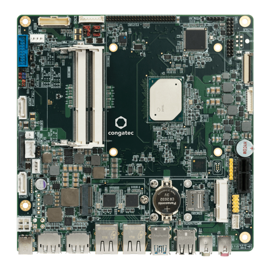
- Page 1 Thin Mini-ITX SBC Detailed Description Of The congatec Thin Mini-ITX Based On Intel® Apollo Lake SoCs User's Guide Revision 0.1 (Preliminary)
-
Page 2: Revision History
Revision History Revision Date (yyyy.mm.dd) Author Changes 2017.07.19 • Preliminary release Copyright © 2017 congatec AG IA50m01 2/59... -
Page 3: Intended Audience
In no event shall congatec AG be liable for any incidental, consequential, special, or exemplary damages, whether based on tort, contract or otherwise, arising out of or in connection with this user’s guide or any other information... -
Page 4: Copyright Notice
Copyright © 2017, congatec AG. All rights reserved. All text, pictures and graphics are protected by copyrights. No copying is permitted without written permission from congatec AG. congatec AG has made every attempt to ensure that the information in this document is accurate, yet the information contained within is supplied “as-is”. - Page 5 (c) arising from course of performance, course of dealing, or usage of trade. congatec AG shall in no event be liable to the end user for collateral or consequential damages of any kind. congatec shall not otherwise be liable for loss, damage or expense directly or indirectly arising from the use of the product or from any other cause.
-
Page 6: Technical Support
Technical Support congatec AG technicians and engineers are committed to providing the best possible technical support for our customers so that our products can be easily used and implemented. We request that you first visit our website at www.congatec.com for the latest documentation, utilities and drivers, which have been made available to assist you. -
Page 7: Table Of Contents
Stereo Speaker Header ............29 Front Panel Connector ............. 50 5.3.2.2 Digital Microphone/SPDIF ............29 Case Open Intrusion Connector ..........51 5.3.2.3 Front Panel HD Audio .............. 30 Trusted Platform Module – TPM (Optional) ......51 Copyright © 2017 congatec AG IA50m01 7/59... - Page 8 Board Controller (cBC) ..........51 API Support (CGOS) ..............54 6.4.1 Fan Control ................51 Thermal/Voltage Monitoring............ 54 6.4.2 Power Loss Control ..............52 Beeper ..................54 6.4.3 Board Information ..............52 6.10 External System Wake Event ........... 54 6.4.4...
- Page 9 List of Tables Table 1 conga-IA5 Commercial Variants ..........12 Table 34 Monitor OFF (Connector X28) Pinout Description ....45 Table 2 conga-IA5 Industrial Variants ........... 12 Table 35 x1 PCIe Slot (Connector X8) Pinout Description ...... 45 Table 3 Cooling/IO Shield ..............
-
Page 10: Introduction
With smaller board size and lower height keep-out zones, the conga-IA5 SBC provides manufacturers and enthusiasts with the opportunity to design compact systems for space restricted areas. With appropriate I/O shield, the same conga-IA5 SBC can be used in either a Thin Mini-ITX or a Mini-ITX design. -
Page 11: Options Information
1.2.1 Options Information The conga-IA5 is currently available in six variants. This user’s guide describes all of these variants. The tables below show the different configurations available. Check for the Part No. that applies to your product. This will tell you what options described in this user’s guide are available on your particular module. -
Page 12: Optional Accessories
Part No. Description conga-Thin MITX/eDP to DP Adapter 052231 eDP to standard DisplayPort evaluation adapter for congatec Thin Mini-ITX boards conga-Thin MITX/eDP to HDMI Adapter 052232 eDP to standard HDMI evaluation adapter for congatec Thin Mini-ITX boards Copyright © 2017 congatec AG... -
Page 13: Specification
® ® ® Memory Two memory sockets (located on the top side of the conga-IA5) with support for: SO-DIMM non-ECC DDR3L modules Data rates up to 1866 MT/s Maximum 8 GB system memory capacity Multi-stage watchdog, manufacturing and board information, board statistics, I2C bus, Power loss control... -
Page 14: Supported Operating Systems
Other Features Thermal and voltage monitoring, CMOS Battery, Beeper congatec Standard BIOS (also possible to boot from an external BIOS by triggering the BIOS_DISABLE# signal on the feature connector) Security Optional discrete Trusted Platform Module “TPM 1.2/2.0”, new AES Instructions for faster and better encryption Note Some of the features mentioned above are optional. -
Page 15: Mechanical Dimensions
• Maximum Height: 20mm Supply Voltage Power • 12V - 24V DC ± 10% Power Consumption The power consumption values were measured with the following setup: • conga-IA5 • conga-IA5 cooling solution • Microsoft ® Windows ® 10 (64-bit) Note... -
Page 16: Supply Voltage Battery Power
Table 9 Power Consumption Values The tables below provide additional information about the power consumption data for each of the conga-IA5 variants offered. The values are recorded at various operating modes. Part Memory BIOS Current (Amp.) Size Rev. Rev. (64-bit) -
Page 17: Environmental Specifications
Storage: 5% to 95% Caution The above operating temperatures must be strictly adhered to at all times. When using a congatec heatspreader, the maximum operating temperature refers to any measurable spot on the heatspreader’s surface. Humidity specifications are for non-condensing conditions. -
Page 18: Block Diagram
High Definition Audio CS4207 HD Audio Digital Mic, (SPDIF) LVDS eDP to LVDS Audio HeadPh Backlight Power External I/O Internal I/O optional Audio MIC Panel Power Located at the bottom side. Monitor Optional feature. Copyright © 2017 congatec AG IA50m01 18/59... -
Page 19: Cooling Solution
Nonetheless, all electronics contain semiconductor devices which have operating temperature ranges that should be adhered to. This means that for reliable operation, the thermal design of the conga-IA5 must be carefully considered. For this reason, it is imperative to provide sufficient air flow to each of the components, to ensure the specified operating temperature of the conga-IA5 is maintained. -
Page 20: Cooling Installation
For applications that require vertically-mounted CSP, use only cooling solution that secure the thermal stacks with fixing post. Without the fixing post feature, the thermal stacks may move. Also, do not exceed the maximum torque specification for the cooling solution screws. Doing so may damage the SBC. Copyright © 2017 congatec AG IA50m01 20/59... -
Page 21: Csp Dimensions
CSP Dimensions CSP Dimensions for Celeron and Pentium Open Die Variants (PN: 052830 — conga-IA5/CSP) ® ® 21.2 19.75 Note All measurements are in millimeters. Recommended maximum torque for cooling solution screws is 0.3 Nm. Mechanical system assembly mounting shall follow the valid DIN/IS0 specifications. - Page 22 CSP Dimensions for Atom™ Lidded Die Variants (PN: 052831 — conga-IA5/i-CSP) 21.2 19.75 Note All measurements are in millimeters. Recommended maximum torque for cooling solution screws is 0.3 Nm. Mechanical system assembly mounting shall follow the valid DIN/IS0 specifications. Copyright © 2017 congatec AG...
-
Page 23: Connector Description
DC Power Jack (Rear I/O) The conga-IA5 SBC can be powered from a laptop type external power supply connected to the DC power jack on the rear I/O. The power input is protected to a short transient over-voltage and ESD. -
Page 24: Power Supply (Internal Connector)
Caution The absolute maximum rating of the input voltage is 26.5 volts. Do not exceed this rating or expose the conga-IA5 to the absolute maximum voltage for a prolonged time. Doing so may damage the system or affect system reliability. -
Page 25: Optional Sbm 3 Power Connector (Internal Connector)
Caution The absolute maximum rating of the input voltage is 26.5 volts. Do not exceed this rating or expose the conga-IA5 to the absolute maximum voltage for a prolonged time. Doing so may damage the system or affect system reliability. -
Page 26: Pwr_Ok Signal
Power Status LEDs The conga-IA5 provides two LED signals (FP_LED+ and P_LED-) on pins 2 and 4 of the front panel connector X39. The signals indicate the different power states of the conga-IA5. Possible states and corresponding activity of the LEDs are shown below:... -
Page 27: Cmos Battery/Rtc
CMOS Battery/RTC The conga-IA5 provides a board-mounted battery holder (M37) for the CMOS battery — CR2032 for commercial variants; BR2330A for industrial variants. The CMOS battery supplies the necessary power required to maintain the CMOS settings and configuration data in the UEFI flash chip. -
Page 28: Rear Audio Connectors
X20: 6 pin, single audio jack — pink color X22: 6 pin, single audio jack — lime color 5.3.2 Internal Audio Connectors The conga-IA5 provides the stereo speaker, digital microphone/SPDIF and front panel HD audio connectors internally. Copyright © 2017 congatec AG IA50m01 28/59... -
Page 29: Stereo Speaker Header
Digital MIC/SPDIF - Connector X19 Signal Description +3.3V 3.3V supply Pin 1 DMIC_DATA Serial data from digital MIC Ground No Pin SPDIFO2 Secondary S/PDIF output No pin 5V supply Connector Type X19: 2.54mm, 1x6 pin header Copyright © 2017 congatec AG IA50m01 29/59... -
Page 30: Front Panel Hd Audio
Communication Bus The conga-IA5 supports both SMBus and I2C compliant devices. 5.4.1 SMBus The SMBus signals are available in different locations on the conga-IA5, including the feature connector (X35) described in section 6.11 of this document. 5.4.2 I²C Bus The congatec Board controller provides I²C signals. These signals are available in different locations on the conga-IA5, including the feature connector (X35) described in section 6.11 of this document. -
Page 31: Spi Bus
Serial Ports (COM) The Super I/O controller on the conga-IA5 provides two UART interfaces (COM 0 and 1). One UART fully featuring RS-232 UART and the other UART featuring RS232 (Rx and Tx only), RS422, and RS485. The COM 1 interface can be optionally used as ccTALK compliant interface. The COM ports can drive up to 115 kbit/s at a maximum cable length of 15 m. -
Page 32: Cpu/System Fan Connector & Power Configuration
CPU/System Fan Connector & Power Configuration The conga-IA5 supports the connection of 5V or 12V cooling fans. The signals of the CPU and system fans are routed to 4-pin connectors X34 and X37 respectively. Use jumper X36 to select the CPU fan voltage and jumper X38 to select the system fan voltage. -
Page 33: Universal Serial Bus (Usb)
Universal Serial Bus (USB) The conga-IA5 provides 6 USB ports — 4 USB ports on the rear side and 2 USB ports internally. All USB ports are routed directly from the SoC. Apollo Lake SoC USB3_P2 to M.2 Connector USB2_P7 to M.2 Connector USB3 to mPCIe Connector 2x USB 2.0 Rear Ports... -
Page 34: Rear Usb Connectors
5.6.1 Rear USB Connectors The conga-IA5 offers four USB ports on the rear side — two USB 2.0 ports on connector X16 and two USB 3.0 ports on connector X17. USB 2.0 - Connector X16 USB 3.0 - Connector X17... -
Page 35: Internal Usb 2.0 Connector
Connector X15 has a maximum current of 0.5A. Ethernet 10/100/1000 The conga-IA5 provides two Gigabit Ethernet ports (connectors X6 and X7) on the rear side. The two Gigabit Ethernet interfaces are supported via the Intel Gigabit Ethernet controller i211 (commercial variants) or i210 (industrial variants). -
Page 36: Sata Interfaces
SATA / SATADOM Ports The conga-IA5 provides two SATA III ports supporting data rates up to 6 Gb/s. SATADOM is featured on connector CN1 — to enable it, set SATA Power to SATADOM in the BIOS configuration. Do not connect a SATA device to connector CN1 if SATA Power is set to SATADOM. -
Page 37: Sata Power
5.8.2 SATA Power The conga-IA5 provides an internal SATA power for hard drives on connector X11. This connector supplies 3.3V, 5V and 12V. SATA Power - Connector X11 6 5 4 3 2 1 Connector Type X11: 15 pin SATA connector Note The voltage rails +3.3V, +5V and +12V have maximum current of 1.5A each. -
Page 38: M.2 Slot
M.2 Slot The conga-IA5 offers an M.2, type 3042/2242 slot (X12) for connecting a SATA or PCIe SSD and WWAN device. This connector shares the SoC's SATA1 signals with CN2. CN2 will not function whenever a device is inserted into the M.2 connector. Therefore, if you plan to use connector CN2, do not insert a device into the M.2 connector. -
Page 39: Display Interfaces
5.9.1 Display Port Interface DP++ The conga-IA5 SBC has two DP++ connectors (X26 and X27) located at the rear I/O panel. The DP++ connectors support DP, HDMI and DVI displays. HDMI and DVI require an external passive cable adapter. DP++ - Connectors X26/X27 Copyright ©... -
Page 40: Lvds
5.9.2 LVDS The conga-IA5 offers LVDS interface on connector X33 — a standard 40 pin LVDS connector. The LVDS signals are sourced from the SoC's DDI stream via a multiplexer. The interface is located on the top side of the SBC and supports 24-bit dual channel, selectable backlight voltage, VESA color mappings, automatic panel detection and up to 1920x1200 resolution. -
Page 41: Embedded Display Port (Edp)
Embedded Display Port (eDP) The conga-IA5 provides an eDP interface at the bottom side on connector X29 — a standard 40-pin DisplayPort connector. The eDP signals are sourced from incoming eDP stream via a multiplexer. The multiplexer routes the eDP signals to LVDS connector X33 (via an eDP to LVDS bridge) by default. -
Page 42: Backlight Power Connector
5.9.3.1 Backlight Power Connector The conga-IA5 provides backlight power on connector X32. The power budget of BKLT_PWR (pins 3 and 4) is limited to 1.5A. Table 31 Backlight Power (Connector X32) Pinout Description Backlight Power - Connector X32... -
Page 43: Backlight/Panel Power Selection
Backlight/Panel Power Selection The conga-IA5 supports different voltages for the panel and backlight connectors. With jumper X30, you can set the backlight voltage to 5V or 12V. With jumper X31, you can set the panel voltage to 3.3V, 5V or 12V. -
Page 44: Monitor Off Connector
X28: 2.54mm, 2 pin Molex connector 5.10 PCI Express The conga-IA5 provides 3 PCIe interfaces — a x1 PCIe slot on connector X8, a half-size mini PCIe (mPCIe) and a full size mini PCIe / mini SATA slot on connector X9. 5.10.1 x1 PCIe Slot The conga-IA5 offers one PCIe x1 slot on connector X8. -
Page 45: Mini Pcie (Half Size)
Mini PCIe (Half Size) The conga-IA5 is equipped with a PCIe Mini Card socket (connector X9). PCI Express Mini Card is a unique small size form factor optimized for mobile computing platforms. The small footprint connector makes it possible to mount upgradable, standardized PCI Express Mini Card device to the SBC without additional expenditure of a redesign. - Page 46 Pull down resistor (1M) N.C. W_DISABLE# PERST# PERn0 +3.3Vaux PERp0 +1.5V SMB_CLK PETn0 SMB_DATA PETp0 USB_D- USB_D+ +3.3Vaux +3.3Vaux mSATA_mPCIe_detect CL_CLK CL_DATA +1.5V CL_RST# N.C. +3.3Vaux Connector Type X9: PCIe mini card socket Copyright © 2017 congatec AG IA50m01 46/59...
-
Page 47: Mini Pcie (Full Size)
5.10.3 Mini PCIe (Full Size) The conga-IA5 offers an mPCIe slot on connector X9. This connector shares the SoC's PCIe 0 signals with connector X8 (x1 PCIe slot), via a multiplexer. When an mPCIe device is attached to the mPCIe slot (connector X9), the SoC automatically detects the type of device that is attached (via pin 43 —... -
Page 48: Micro-Sim Slot
5.12 Micro-SD Slot The conga-IA5 offers a micro-SD slot on connector X41. The SD card slot complies with SDXC card specification 3.0 with support for up to 104 MBps data rate. Micro-SD Slot - Connector X41 Connector Type X41: Micro-SD slot Copyright ©... -
Page 49: Pci Express Routing
M.2 device into connector X12. Connector X12 The SIM Slot (X10) can be connected to SATA1 Signals either mPCIe Slot (X9) or M.2 Slot (X12). PCIe5 (Alternatively, can be configured as USB 3.0) USB 2.0 Signals Copyright © 2017 congatec AG IA50m01 49/59... -
Page 50: Additional Features
Front Panel Connector The conga-IA5 SBC supports front panel features such as power button, status LEDs and reset button via connector X39 — a 10-pin internal header. This connector offers one power supply pin (3.3V). The signals FP_LED+ and FP_LED- communicates the system states to two LEDs connected to this header. -
Page 51: Case Open Intrusion Connector
The conga-IA5 is equipped with a Texas Instruments Tiva™ TM4E1231H6ZRBI microcontroller. This onboard microcontroller plays an important role for most of the congatec BIOS features. It fully isolates some of the embedded features such as system monitoring or the I²C bus from the x86 core architecture, which results in higher embedded feature performance and more reliability, even when the x86 processor is in a low power mode. -
Page 52: Power Loss Control
It also keeps track of dynamically changing data like runtime meter and boot counter. 6.4.4 GPIOs The conga-IA5 SBC provides eight General Purpose Inputs via the congatec board controller and eight General Purpose Outputs via the onboard Super I/O. The GPIO signals are routed to the feature connector X35. OEM BIOS Customization The conga-IA5 is equipped with congatec Embedded BIOS, which is based on American Megatrends Inc. -
Page 53: Oem Post Logo
OEM POST Logo This feature allows system designers to replace the congatec POST logo displayed in the upper left corner of the screen during BIOS POST with their own BIOS POST logo. Use the congatec system utility CGUTIL 1.5.4 or later to replace/add the OEM POST logo. -
Page 54: Api Support (Cgos)
The architecture of the CGOS API driver provides the ability to write application software that runs unmodified on all congatec CPU modules. All the hardware related code is contained within the congatec embedded BIOS on the module. See section 1.1 of the CGOS API software developers guide, which is available on the congatec website. -
Page 55: Feature Connector
6.11 Feature Connector The conga-IA5 provides an internal 50 pol. 2mm pin header as feature connector. The pinout is described below: Table 40 Feature Connector (Connector X35) Pinout Description Feature Connector - Connector X35 Signal Signal +V5S LAD0 LAD1 LAD2... -
Page 56: Conga-Ia5 Mechanical Drawing
Mechanical Drawing Copyright © 2017 congatec AG IA50m01 56/59... -
Page 57: Bios Setup Description
BIOS Setup Description T.B.D Copyright © 2017 congatec AG IA50m01 57/59... -
Page 58: Additional Bios Features
Additional BIOS Features T.B.D Copyright © 2017 congatec AG IA50m01 58/59... -
Page 59: Industry Specifications
Industry Specifications The list below provides links to industry specifications that apply to congatec AG modules. Specification Link Low Pin Count Interface Specification, Revision 1.0 (LPC) http://developer.intel.com/design/chipsets/industry/lpc.htm Universal Serial Bus (USB) Specification, Revision 2.0 http://www.usb.org/home PCI Specification, Revision 2.3 http://www.pcisig.com/specifications Serial ATA Specification, Revision 3.0...
Need help?
Do you have a question about the conga-IA5 and is the answer not in the manual?
Questions and answers