
Related Manuals for Congatec COM Express conga-MA5


Summary of Contents for Congatec COM Express conga-MA5
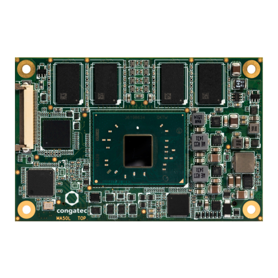
- Page 1 COM Express™ conga-MA5 COM Express Type 10 Mini module based on the Intel® Atom®, Pentium® and Celeron® Apollo Lake SoC User's Guide Revision 1.7...
- Page 2 Added reference to BIOS Setup Description application note in section 10 "BIOS Setup Description" • Updated section 11 "Industry Specifications" 2021.02.19 • Corrected the storage temperature for industrial variants in section 2.7 “Environmental Specifications” Copyright © 2017 congatec AG MA50m17 2/60...
- Page 3 The information contained within this user's guide, including but not limited to any product specification, is subject to change without notice. congatec AG provides no warranty with regard to this user's guide or any other information contained herein and hereby expressly disclaims any implied warranties of merchantability or fitness for any particular purpose with regard to any of the foregoing.
- Page 4 Copyright © 2017, congatec AG. All rights reserved. All text, pictures and graphics are protected by copyrights. No copying is permitted without written permission from congatec AG. congatec AG has made every attempt to ensure that the information in this document is accurate yet the information contained within is supplied “as-is”.
- Page 5 (c) arising from course of performance, course of dealing, or usage of trade. congatec AG shall in no event be liable to the end user for collateral or consequential damages of any kind. congatec shall not otherwise be liable for loss, damage or expense directly or indirectly arising from the use of the product or from any other cause.
- Page 6 Technical Support congatec AG technicians and engineers are committed to providing the best possible technical support for our customers so that our products can be easily used and implemented. We request that you first visit our website at www.congatec.com for the latest documentation, utilities and drivers, which have been made available to assist you.
-
Page 7: Table Of Contents
Rise Time ................. 14 Onboard Interfaces ..............33 Power Consumption ..............15 6.1.1 eMMC 5.0 ................33 Supply Voltage Battery Power ..........16 congatec Board Controller (cBC) ..........33 Environmental Specifications ........... 17 6.2.1 Board Information ..............33 Block Diagram ................18 6.2.2 Fan Control ................ - Page 8 Signal Descriptions and Pinout Tables ........40 SM Bus ..................56 congatec System Sensors ............57 COM Express Connector Pinout ..........41 COM Express Connector Signal Descriptions ......43 BIOS Setup Description ............58 System Resources ..............54 10.1 Navigating the BIOS Setup Menu ........... 58 10.2...
- Page 9 Table 32 SM Bus Signal Descriptions ............. 51 Table 33 General Purpose I/O Signal Descriptions ........ 51 Table 34 SDIO Signal Descriptions ............52 Table 35 Module Type Definition Signal Description ......52 Copyright © 2017 congatec AG MA50m17 9/60...
-
Page 10: Introduction
Simply unplug one module and replace it with another, no redesign is necessary. Copyright © 2017 congatec AG MA50m17... -
Page 11: Table 2 Conga-Ma5 Commercial Variants
(SLC / MLC) Onboard 16 GB MLC Onboard 16 GB MLC Onboard 16 GB MLC Ethernet Controller Intel I210 Intel I210 Intel I210 ® ® ® 12 W 9.5 W 6.5 W SOC TDP Copyright © 2017 congatec AG MA50m17 11/60... -
Page 12: Specifications
BIOS AMI Aptio ® UEFI 5.x firmware; 8 MByte serial SPI with congatec Embedded BIOS features (OEM Logo, OEM CMOS Defaults, LCD Control, Display Auto Detection, Backlight Control, Flash Update) Power Mgmt. ACPI 5.0 compliant with battery support. Also supports Suspend to RAM (S3). -
Page 13: Supported Operating Systems
• Yocto 2.x Note For the installation of Microsoft Windows 10 (64-bit), congatec recommends a minimum storage capacity of 20 GB. congatec will not offer ® ® technical support for systems with less than 20 GB storage space. Mechanical Dimensions •... -
Page 14: Supply Voltage Standard Power
The input voltages shall rise from 10% of nominal to 95% of nominal within 0.1 ms to 20 ms (0.1 ms ≤ Rise Time ≤ 20 ms). Each DC input voltage must rise from 10% to 90% of its nominal voltage in a smooth, continuous ramp and the slope of the turn-on waveform must be positive. Copyright © 2017 congatec AG MA50m17... -
Page 15: Power Consumption
Power Consumption The power consumption values were measured with the following setup: • conga-MA5 COM • modified congatec carrier board • conga-MA5 cooling solution • Microsoft Windows 10 (64-bit) ® Note The CPU was stressed to its maximum workload with the Intel Thermal Analysis Tool. -
Page 16: Supply Voltage Battery Power
With fast input voltage rise time, the inrush current may exceed the measured peak current. Supply Voltage Battery Power Table 8 CMOS Battery Power Consumption RTC @ Voltage Current 3V DC 1.90 µA 3V DC 2.31 µA 3V DC 5.46 µA Copyright © 2017 congatec AG MA50m17 16/60... -
Page 17: Environmental Specifications
Storage: 5% to 95% Caution The above operating temperatures must be strictly adhered to at all times. When using a congatec heatspreader, the maximum operating temperature refers to any measurable spot on the heatspreader’s surface. Humidity specifications are for non-condensing conditions. -
Page 18: Block Diagram
UART Port 1-0 SIO Assembly Option LPC Bus GPIO Notes: SM Bus : PCIe 3 is available only for config x4 or no GbE congatec I2C Bus Board Controller PWR control FAN control Copyright © 2017 congatec AG MA50m17 18/60... -
Page 19: Cooling Solutions
Cooling Solutions congatec AG offers the cooling solutions listed in Table 9 for conga-MA5. The dimensions of the cooling solutions are shown in the sub-sections. All measurements are in millimeters. Table 9 Cooling Solution Variants Cooling Solution Part No Description 048057 Heatspreader with 2.7 mm bore-hole standoffs for lidded CPU Intel Atom CPU variants... -
Page 20: Csp Dimensions
CSP Dimensions For Lidded Variants M2.5 x 6 mm threaded standoff for threaded version ø2.7 x 6 mm non-threaded standoff for borehole version Copyright © 2017 congatec AG MA50m17 20/60... - Page 21 For Bare-die Variants M2.5 x 6 mm threaded standoff for threaded version ø2.7 x 6 mm non-threaded standoff for borehole version Copyright © 2017 congatec AG MA50m17 21/60...
-
Page 22: Heatpsreader Dimensions
Heatpsreader Dimensions For Lidded Variants M2.5 x 6 mm threaded standoff for threaded version ø2.7 x 6 mm non-threaded standoff for borehole version Copyright © 2017 congatec AG MA50m17 22/60... - Page 23 For Bare-die Variants M2.5 x 6 mm threaded standoff for threaded version ø2.7 x 6 mm non-threaded standoff for borehole version Copyright © 2017 congatec AG MA50m17 23/60...
-
Page 24: Connector Subsystems Rows A, B
5 Gb/s bandwidth in each direction per x1 link. Default configuration for the lanes is 3 x1 link. Other configurations are possible as shown in the table below but require a customized BIOS firmware. Contact congatec technical support for more information. -
Page 25: Sata
To pass the Electrical Fast Transient (EFT) test, you must add a schottky diode (1SS402 or equivalent) to all USB2.0 data lanes routed to a connector on your carrier board. The schottky diode must be placed before the common-mode choke as shown below. Copyright © 2017 congatec AG MA50m17... -
Page 26: Usb 3.0
To support the HDMI/DVI interface, implement an external level translator/shifter (e.g. PTN3360D) on the carrier board. To support the maximum resolution of the DP or HDMI/DVI, implement a retimer. For non-default display configuration, you need a customized conga-MA5 variant. Copyright © 2017 congatec AG MA50m17 26/60... -
Page 27: Displayport (Dp)
The conga-MA5 supports one DVI interface with resolution up to 1920x1200 @60Hz. Note To support the DVI interface, implement an external level translator/shifter (e.g. PTN3360D) on the carrier board. See Table 11 for possible display combinations. Copyright © 2017 congatec AG MA50m17 27/60... -
Page 28: Lvds/Edp
• resolution up to 1280x1024 @60Hz The LVDS interface provides LVDS signals by default, but can optionally support eDP 1.3 signals at 3840x2160 @60Hz (assembly option). For more information, contact congatec technical support. Note The LVDS/eDP interface supports either LVDS or eDP signals. Both signals are not supported simultaneously. See Table 11 for possible display combinations. -
Page 29: Lpc Bus
3V 8 MByte SPI Flash device with SFDP feature (e.g. W25Q64FVSSIG) can be utilized to boot the module. The SPI clock speed is 25 MHz. 5.12 I²C Bus The I²C bus is implemented through the congatec board controller. The bus has 2.2k ohm pull-ups resistors on the CLK and DATA signals and is powered from standby 3.3V. 5.13 SMBus The SM Bus is implemented through the congatec board controller. - Page 30 With this solution, you must make sure that by the time the 3.3V is up, all carrier board hardware is fully powered and all clocks are stable. The conga-MA5 provides support for controlling ATX-style power supplies. When not using an ATX power supply then the conga-MA5's pins SUS_S3/PS_ON, 5V_SB, and PWRBTN# should be left unconnected. Copyright © 2017 congatec AG MA50m17 30/60...
-
Page 31: Power Management
(approx. 150μs) and with a voltage rise time of 100μs. Sufficient decoupling capacitance must be implemented on the carrier board to ensure proper power-up sequencing. 5.15 Power Management ACPI 5.0 compliant with battery support. Also supports Suspend to RAM (S3). Copyright © 2017 congatec AG MA50m17 31/60... -
Page 32: Mipi Csi-2
Do not try to pull the flat-foil connector out without removing the cooling solution and opening the actuator first. Also, do not use pressure to open the actuator by more than 45°. Otherwise, the connector will be damaged. Copyright © 2017 congatec AG MA50m17... -
Page 33: Additional Features
The conga-MA5 is equipped with a Texas Instruments Tiva™ TM4E1231H6ZRBI microcontroller. This onboard microcontroller plays an important role for most of the congatec BIOS features. It fully isolates some of the embedded features such as system monitoring or the I²C bus from the x86 core architecture, which results in higher embedded feature performance and more reliability, even when the x86 processor is in a low power mode. -
Page 34: Power Loss Control
OEM BIOS Customization The conga-MA5 is equipped with congatec Embedded BIOS, which is based on American Megatrends Inc. Aptio UEFI firmware. The congatec Embedded BIOS allows system designers to modify the BIOS. For more information about customizing the congatec Embedded BIOS, refer to the congatec System Utility user’s guide CGUTLm1x.pdf on the congatec website at www.congatec.com or contact technical support. -
Page 35: Oem Boot Logo
OEM POST Logo This feature allows system designers to replace the congatec POST logo displayed in the upper left corner of the screen during BIOS POST with their own BIOS POST logo. Use the congatec system utility CGUTIL 1.5.4 or later to replace/add the OEM POST logo. -
Page 36: Api Support (Cgos)
The CGOS API (congatec Operating System Application Programming Interface) is the congatec proprietary API that is available for all commonly used Operating Systems such as Win32, Win64, Linux. The architecture of the CGOS API driver provides the ability to write application software that runs unmodified on all congatec CPU modules. -
Page 37: Conga Tech Notes
Intel architecture microprocessors and chipsets. Intel Virtualization Technology for IA-32, Intel 64 and Intel Architecture ® ® ® Intel ® VT-x added hardware support in the processor to improve the virtualization performance and robustness. Copyright © 2017 congatec AG MA50m17 37/60... -
Page 38: Ahci
Note congatec does not offer virtual machine monitor (VMM) software. All VMM software support questions and queries should be directed to the VMM software vendor and not congatec technical support. 7.1.1.2 AHCI The Apollo Lake SoC provides hardware support for Advanced Host Controller Interface (AHCI), a programming interface for SATA host controllers. -
Page 39: Acpi Suspend Modes And Resume Events
In Device Manager look for the keyboard/mouse devices. Go to the Power Management tab and check ‘Allow this device to bring the computer out of standby'. RTC Alarm Activate and configure Resume On RTC Alarm in the Power setup menu. Only available in S5. Watchdog Power Button Event Wakes unconditionally from S3-S5. Copyright © 2017 congatec AG MA50m17 39/60... -
Page 40: Signal Descriptions And Pinout Tables
Signal Descriptions and Pinout Tables The following section describes the signals found on COM Express™ Type 10 connectors used for congatec AG modules. The pinout of the modules complies with COM Express Type 10 Rev. 2.1. The table below describes the terminology used in this section for the Signal Description tables. The PU/PD column indicates if a COM Express™... -
Page 41: Com Express Connector Pinout
GPI3 VCC_5V_SBY A31 GND(FIXED) GND(FIXED) RSVD VCC_5V_SBY A32 HDA_BITCLK SPKR eDP_HPD VCC_5V_SBY A33 HDA_SDOUT I2C_CK PCIE_CLK_REF+ BIOS_DIS1# A34 BIOS_DIS0# I2C_DAT PCIE_CLK_REF- DD0_HPD A35 THRMTRIP# THRM# GND(FIXED) GND(FIXED) A36 USB6- USB7 SPI_POWER DDI0_PAIR5+ (*) Copyright © 2017 congatec AG MA50m17 41/60... - Page 42 COM Express Specification. To comply with the COM Express Specification, the signals are routed through bidirectional level shifters on the module. The bidirectional level shifters by nature have limited driving strenght. congatec therefore recommends that you route these signals as short as possible. External pull up/down resistors <100k ohm are not allowed on these signals.
-
Page 43: Com Express Connector Signal Descriptions
Express Specification. To comply with the COM Express Specification, the signals are routed through bidirectional level shifters on the module. The bidirectional level shifters by nature have limited driving strenght. congatec therefore recommends that you route these signals as short as possible. -
Page 44: Table 17 Serial Ata Signal Descriptions
PCI Express Reference Clock output for all PCI Express O PCIE A PCI Express Gen2/3 compliant clock buffer chip must be used on PCIE_CLK_REF- lanes. the carrier board if more than one PCI Express device is designed in. Copyright © 2017 congatec AG MA50m17 44/60... -
Page 45: Table 19 Expresscard Support Pins Signal Descriptions
Do not pull this line high on the carrier board. shall be present on the module. An open drain driver from a USB 3.3VSB current monitor on the carrier board may drive this line low. Copyright © 2017 congatec AG MA50m17 45/60... -
Page 46: Table 21 Lvds Signal Descriptions
Assembly option: eDP LVDS_I2C_DAT DDC lines used for flat panel detection and control. I/O 3.3V LVDS PU LVDS (default) eDP_AUX- Embedded Display Port AUX channel pair I/O eDP 2k2 3.3V Assembly option: eDP Copyright © 2017 congatec AG MA50m17 46/60... -
Page 47: Table 22 Lpc Signal Descriptions
COM Express Specification. To comply with the COM Express Specification, the signals are routed through bidirectional level shifters on the module. The bidirectional level shifters by nature have limited driving strenght. congatec therefore recommends that you route these signals as short as possible. -
Page 48: Table 24 Ddi Signal Descriptions
Half-duplex bi-directional AUX channel for services such as link configuration or PD 100k maintenance and EDID access. DP0_AUX- Half-duplex bi-directional AUX channel for services such as link configuration or PU 100k 3.3V maintenance and EDID access. Copyright © 2017 congatec AG MA50m17 48/60... -
Page 49: Table 26 Hdmi/Dvi Signal Descriptions
Signal Pin # Description PU/PD Comment I2C_CK General purpose I2C port clock output I/O OD 3.3VSB PU 2.2K 3.3VSB I2C_DAT General purpose I2C port data I/O line I/O OD 3.3VSB PU 2.2K 3.3VSB Copyright © 2017 congatec AG MA50m17 49/60... -
Page 50: Table 29 Miscellaneous Signal Descriptions
Sleep button. Used by the ACPI operating system to bring the system to sleep state or to wake it up again. I 3.3VSB PU 47k 3.3VSB Note: For proper detection, assert a pulse width of at least 16 ms. Copyright © 2017 congatec AG MA50m17 50/60... -
Page 51: Table 31 Thermal Protection Interface Signal Descriptions
General purpose output pins. O 3.3V Shared with SD_WP. Output from COM Express, input to SD GPO3 General purpose output pins. O 3.3V Shared with SD_CD. Output from COM Express, input to SD Copyright © 2017 congatec AG MA50m17 51/60... -
Page 52: Table 34 Sdio Signal Descriptions
A51, A57, A60, A66, A70, All available GND connector pins shall be used and tied to carrier A80, A90, A100, A110 board GND plane. B1, B11, B21, B31, B41, B51, B60, B70, B80, B90, B100, B110 Copyright © 2017 congatec AG MA50m17 52/60... -
Page 53: Table 37 Can Bus Signal Descriptions
Controller Area Network TX output for CAN Bus channel 0. This O 3.3V Not supported pin is shared with SER1_TX CAN0_RX A102 Controller Area Network RX input for CAN Bus channel 0. This I 3.3V Not supported pin is shared with SER1_RX Copyright © 2017 congatec AG MA50m17 53/60... -
Page 54: System Resources
On the conga-MA5, the internal PCI Bus acts as the substractive decoding agent. All I/O cycles that are not positively decoded are forwarded to the PCI Bus, not the LPC Bus. Only specified I/O ranges are forwarded to the LPC Bus. With the default settings in the congatec Embedded... -
Page 55: Pci Configuration Space Map
Parts of these ranges are not available if Super I/O is used on the carrier board. If Super I/O is not implemented on the carrier board, then all these ranges are available for customer use. If you require additional LPC Bus resources other than those mentioned above, or more information about this subject, contact congatec technical support for assistance. PCI Configuration Space Map... -
Page 56: I²C Bus
This device is disabled as default in BIOS Setup. I²C Bus There are no onboard resources connected to the I²C bus. Address 16h is reserved for congatec Battery Management solutions. SM Bus System Management (SM) bus signals are connected to the Intel Apollo Lake SoC and the SM bus is not intended to be used by off-board non-system management devices. -
Page 57: Congatec System Sensors
– CPU temperature based on CPU digital thermal sensor – Board temperature sensor located on the board controller • Two voltage sensors – DC Input voltage sensor – 5V standby voltage sensor • One fan monitor Copyright © 2017 congatec AG MA50m17 57/60... -
Page 58: Bios Setup Description
10.1 Navigating the BIOS Setup Menu The BIOS setup menu shows the features and options supported in the congatec BIOS. To access and navigate the BIOS setup menu, press the <DEL> or <F2> key during POST. The right frame displays the key legend. Above the key legend is an area reserved for text messages. These text messages explain the options and the possible impacts when changing the selected option in the left frame. -
Page 59: Updating The Bios
BIOS updates are recommended to correct platform issues or enhance the feature set of the module. The conga-MA5 features a congatec/AMI AptioEFI firmware on an onboard flash ROM chip. You can update the firmware with the congatec System Utility. The utility has five versions—... -
Page 60: Industry Specifications
Universal Serial Bus (USB) Specification, Revision 2.0 www.usb.org PCI Specification, Revision 2.3 www.pcisig.com/specifications Serial ATA Specification, Revision 3.0 www.serialata.org PICMG ® COM Express Module™ Base Specification www.picmg.org PCI Express Base Specification, Revision 1.0a www.pcisig.com/specifications Copyright © 2017 congatec AG MA50m17 60/60...
Need help?
Do you have a question about the COM Express conga-MA5 and is the answer not in the manual?
Questions and answers