
Related Manuals for Congatec conga-TEVAL/COMe 3.0


Summary of Contents for Congatec conga-TEVAL/COMe 3.0
- Page 1 3.0 Detailed description of the congatec COM Express™ Type 6 revision 3.0 evaluation carrier board User’s Guide Revision 1.1 Copyright © 2018 congatec AG TEVA2m11 1/56...
- Page 2 Added section 1.3 “Order Number” • Corrected the storage temperature in section 4.3 “Environmental Specifications” • Changed conga-TEVAL2 to conga-TEVAL/COMe 3.0 • Corrected LED D68 color description in table 9 “Power LEDs Status” • Changed the warning icons in sections 4.9.1 “Disk Drive Power Connector” and 4.15 “LPC/eSPI” to caution icon Copyright ©...
- Page 3 In no event shall congatec AG be liable for any incidental, consequential, special, or exemplary damages, whether based on tort, contract or otherwise, arising out of or in connection with this user’s guide or any other information...
- Page 4 Copyright © 2018, congatec AG. All rights reserved. All text, pictures and graphics are protected by copyrights. No copying is permitted without written permission from congatec AG. congatec AG has made every attempt to ensure that the information in this document is accurate yet the information contained within is supplied “as-is”.
- Page 5 (c) arising from course of performance, course of dealing, or usage of trade. congatec AG shall in no event be liable to the end user for collateral or consequential damages of any kind. congatec shall not otherwise be liable for loss, damage or expense directly or indirectly arising from the use of the product or from any other cause.
- Page 6 Technical Support congatec AG technicians and engineers are committed to providing the best possible technical support for our customers so that our products can be easily used and implemented. We request that you first visit our website at www.congatec.com for the latest documentation, utilities and drivers, which have been made available to assist you.
- Page 7 LVDS Panel and Backlight Power Supply ......... 32 COM Express™ Concept ............10 4.7.3.4 Flat Panel and Backlight Voltage Selection ......32 conga-TEVAL/COMe 3.0 ............10 4.7.3.5 Flat Panel and Backlight Power Supply Connection ....33 Order Number ................. 11 4.7.3.6...
- Page 8 Power ..................52 5.1.2 Reset ..................52 5.1.3 LID .................... 52 5.1.4 Sleep ..................53 Beeper ..................53 Ground Test Points ..............53 Debug Display ................. 54 Mechanical Dimensions ............55 Industry Specifications ............. 56 Copyright © 2018 congatec AG TEVA2m11 8/56...
- Page 9 X26 - External SATA Activity LED ..........37 Table 32 X24 - SATA Power Pinout Description ........38 Table 33 GbE (X32) Status LEDs ............. 38 Table 34 JP2 - Ethernet LEDs Power Configuration ....... 38 Copyright © 2018 congatec AG TEVA2m11 9/56...
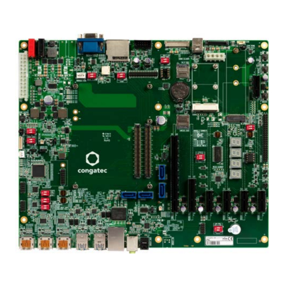
- Page 10 3.0 The conga-TEVAL/COMe 3.0 carrier board is designed based on the Type 6 pinout definition and it complies with COM Express Specification 3.0. The conga-TEVAL/COMe 3.0 provides most of the functional requirements for any embedded PC application. These functions include, but are not limited to a rich complement of contemporary high bandwidth serial interfaces such as PCI Express, Serial ATA, USB 2.0, and Gigabit...
- Page 11 Order Number Table 1 Order Description Part Number Product Name Description 065810 conga-TEVAL2 (conga-TEVAL/COMe 3.0) Evaluation carrier board for COM Express Type 6 rev 3.0 modules Copyright © 2018 congatec AG TEVA2m11 11/56...
- Page 12 Use the mouse icon in the top left hand corner of the destination page to return to the connector layout picture. Copyright © 2018 congatec AG TEVA2m11 12/56...
- Page 13 Multi-channel low power HD audio codec (Cirrus CS4207) Super I/O (Nuvoton NCT6112D) Note The module must also support the features for them to function. Refer to the module’s user’s guide for information about supported features. Copyright © 2018 congatec AG TEVA2m11 13/56...
- Page 14 Storage: 5% to 95% Note The above operating temperatures must be strictly adhered to at all times. The maximum operating temperature refers to any measurable spot on the modules surface. Humidity specifications are for non-condensing conditions. Copyright © 2018 congatec AG TEVA2m11 14/56...
- Page 15 GND (FIXED) GND (FIXED) SATA2_RX- SATA3_RX- eDP_TX3+/LVDS_A_CK+ LVDS_B_CK+ BATLOW# eDP_TX3-/LVDS_A_CK- LVDS_B_CK- (S)ATA_ACT# HDA_SDIN2 eDP_AUX+/LVDS_I2C_CK eDP/LVDS_BKLT_CTRL HDA_SYNC HDA_SDIN1 eDP_AUX-/LVDS_I2C_DAT VCC_5V_SBY HDA_RST# HDA_SDIN0 GPI3 VCC_5V_SBY GND (FIXED) GND (FIXED) RSVD VCC_5V_SBY HDA_BITCLK SPKR eDP_HPD VCC_5V_SBY Copyright © 2018 congatec AG TEVA2m11 15/56...
- Page 16 GND (FIXED) GND (FIXED) A106 VCC_12V B106 VCC_12V PCIE_TX5+ PCIE_RX5+ A107 VCC_12V B107 VCC_12V PCIE_TX5- PCIE_RX5- A108 VCC_12V B108 VCC_12V GPI0 GPO1 A109 VCC_12V B109 VCC_12V PCIE_TX4+ PCIE_RX4+ A110 GND (FIXED) B110 GND (FIXED) Copyright © 2018 congatec AG TEVA2m11 16/56...
- Page 17 PEG_TX9- RSVD RSVD RSVD RSVD DDI1_PAIR5+ DDI1_PAIR1+ DDI1_PAIR5- DDI1_PAIR1- PEG_RX10+ PEG_TX10+ GND (FIXED) GND (FIXED) PEG_RX10- PEG_TX10- DDI2_CTRLCLK_AUX+ DDI1_PAIR2+ DDI2_CTRLDATA_AUX- DDI1_PAIR2- PEG_RX11+ PEG_TX11+ DDI2_DDC_AUX_SEL DDI1_DDC_AUX_SEL PEG_RX11- PEG_TX11- RSVD RSVD GND (FIXED) GND (FIXED) Copyright © 2018 congatec AG TEVA2m11 17/56...
- Page 18 C110 GND (FIXED) D110 GND (FIXED) Power Supply Connector The conga-TEVAL/COMe 3.0 provides the following connectors for power supply: • standard 24-pin ATX connector (X63) • 12 V DC banana jack (X41 and X42) Note 1. In ATX mode, the +3.3 V, +5 V and +12 V are derived from the ATX power supply. If you supply 12 V DC power via the DC banana jack, the onboard DC/DC regulators will generate the 3.3 V, 5 V and 12 V.
- Page 19 ATX Power Connector The conga-TEVAL/COMe 3.0 provides a standard 24-pin connector X63 for ATX power supply. With ATX power supply, the COM Express™ module starts after you press the power-on button SW16 (ATX mode). To configure the power supply to operate in AT mode, set DIP SW21.1 to ON.
- Page 20 DC Banana Jack The conga-TEVAL/COMe 3.0 provides banana jacks X41 and X42 for DC power supply. This power supply supplies power to both the module and the voltage regulators on the carrier board. Although the carrier board is designed for input voltage range of 6 -21 V, the input voltage range is defined by the module (usually 12 V).
- Page 21 4.3.3 Status LEDs D68-D72, D84-D86 The status LEDs indicate the different power states of the conga-TEVAL/COMe 3.0. You can connect an external power LED to pin header X58. Table 10 Power LEDs Status D84 D85 D86 LED Status Description No power applied.
- Page 22 With the deassertion, the system transitions to Full-On state (S0). 4.3.6 Power Consumption Header The conga-TEVAL/COMe 3.0 offers optional pin headers X3 and X4 for measuring the power consumption of the COM Express module Table 12 X3/X4 - Power Consumption Measurement...
- Page 23 ‘PS_ON#’ signal of the ATX power supply. CMOS Battery Holder The conga-TEVAL/COMe 3.0 provides holder M30 for attaching a CR2032 CMOS battery. The battery supplies power to the RTC and CMOS memory. To disconnect the RTC battery, set jumper JP8 to position 2-3.
- Page 24 PCIe Connectors The conga-TEVAL/COMe 3.0 provides: • one PEG x16 slot connector X6 (PEG lanes 0–15) • one x4 PCIe slot connector X9 (PCIe lanes 0–3) • five x1 PCIe slot connectors X7,X8,X10,X14 and X19 (PCIe lanes 1–3, 5 and 7) •...
- Page 25 X6: PCIe x16 card 4.5.2 PCIe x4 Slot The conga-TEVAL/COMe 3.0 provides a standard PCIe x4 slot connector X9 (Slot 0). This slot, which is routed to the module’s PCIe lanes 0–3, shares: • PCIe lane 1 with connector X10 (Slot 1) •...
- Page 26 Mini PCIe Socket The conga-TEVAL/COMe 3.0 provides a standard mini PCIe socket connector X16. This socket is routed to the module’s PCIe lane 6 and USB port 5. The LEDs D6–D8 indicate activity of the card attached to the socket.
- Page 27 4.5.5 The conga-TEVAL/COMe 3.0 provides a standard M.2 Key B slot connector X12. The slot is routed to the module’s PCIe lanes 4 and 5, and USB port 4. It supports WWAN and Intel Optane memory devices. LED D3 lights when there is activity on the M.2 port.
- Page 28 SD Card Slot The conga-TEVAL/COMe 3.0 features a full-size SD card slot connector X28. The slot is routed to the module’s SDIO interface, which is multiplexed with GPIO. The conga-TEVAL/COMe 3.0 demultiplexes the shared signals, and routes the demultiplexed signals to either the SD card slot (SDIO mode) or the feature connector (GPIO mode).
- Page 29 DP++ The conga-TEVAL/COMe 3.0 provides three DP++ interfaces on connectors X35, X36 and X37. The DP++ ports on connector X35 (port 0) and connector X37 (port 3) are routed through a DisplayPort re-driver to support HBR3 data rate (up to 8.1 Gbps).
- Page 30 N.C. eDP]_AUX+ N.C. eDP_AUX- BKLT_PWR PANEL_PWR BKLT_PWR PANEL_PWR BKLT_PWR PANEL_PWR N.C. Connector Type X39: 0.5 mm , 40 Pos. ACES series 50204 connector Copyright © 2018 congatec AG TEVA2m11 30/56...
- Page 31 LVDS_DDC_DAT LVDS0_D3+ LVDS_DDC_CLK LVDS0_D3- LVDS1_D0- LVDS1_D0+ LVDS0_D0- LVDS0_D0+ LVDS1_D1- LCD0_VDD_EN LVDS1_D1+ LVDS0_D1- LVDS0_D1+ LVDS1_D2- LCD0_BKLTEN LVDS1_D2+ LVDS0_D2+ LVDS0_D2- LVDS1_CLK+ LVDS1_CLK LVDS0_CLK- LVDS0_CLK+ LVDS1_D3+ LVDS1_D3- Connector Type X38: 2 mm, 2 x 17-pin socket Copyright © 2018 congatec AG TEVA2m11 31/56...
- Page 32 4.7.3.4 Flat Panel and Backlight Voltage Selection The conga-TEVAL/COMe 3.0 supports different voltages for the panel and backlight. Follow the descriptions in the tables below to set the panel and backlight voltages, and the polarity of the backlight enable signal.
- Page 33 Flat Panel and Backlight Power Supply Connection 2.0A +12V [4] +12V 1.5A [3] +5V +3.3V LVDS_VDD_EN 1.5A [1] VDD_LCD LFP_BKLT_EN_SEL [5] LCD0_VDD_EN 2.0A [2] VDD_BKLT [6] LCD0_BKLT_EN LVDS_BKLT_CTRL [8] LCD0_BKLT_PWM [9] GND [10] GND Copyright © 2018 congatec AG TEVA2m11 33/56...
- Page 34 The flat panel configuration data (EPI extended EDID™ 1.3 file) for most common displays is included in the congatec COM Express™ CPU module’s system BIOS. On the conga-TEVAL/COMe 3.0, you can store a customized EPI extended EDID™ 1.3 file in a serial EEPROM located on DIL SOIC8 socket U35. The following EEPROMs are supported at address A0h: •...
- Page 35 Dual Stacked USB 3.1 Type-A The conga-TEVAL/COMe 3.0 provides four USB 3.1 ports via two dual-stacked USB Type-A connectors (X29 and X30). Each port provides up to one ampere. The lower slot of connector X29 shares the module’s USB port 0 signals with the USB client port (connector X31).
- Page 36 USB Type-B (Client Mode) The conga-TEVAL/COMe 3.0 provides a USB 2.0 Type B connector X31 for USB client mode. Its USB signals are shared with USB port 0 (lower slot of USB connector X29). Use DIP SW5.1 to route the shared signals to connector X31 (client port). For DIP SW5.1 configuration, see table 27 “SW 5.1 Description”.
- Page 37 SATA/SATADOM The conga-TEVAL/COMe 3.0 provides four standard SATA connectors (X20 - X23). SATADOM devices are supported on only connector X20 (SATA0). To enable SATADOM on X20, set jumper JP1 to position 2-3. The 5 V power rail on SATA0 pin 7 (SATADOM mode) is protected by 0.5A fuse.
- Page 38 X24: 15-pin standard SATA power connector 4.10 Gigabit Ethernet (GbE) The conga-TEVAL/COMe 3.0 provides a gigabit Ethernet port on a standard RJ45 connector (X32). Use jumper JP2 to set the power rail for the status LEDs on connector X32. Table 33...
- Page 39 1. To disable the onboard codec, set DIP SW 9.2 to ON. See section 4.11.4 “HDA Adapter/Debug Header” for DIP SW 9.2 configuration . 2. The Windows driver for the codec can be found on the congatec website at www.congatec.com in the ‘Products’ section under ‘Accessories.
- Page 40 A_GND Analog ground MIC-IN Connector Type X47 Upper Jack: 3-pin, 3.5 mm single audio jack 4.11.3 Optical S/PDIF-Out The conga-TEVAL/COMe 3.0 provides S/PDIF-OUT signal on connector X48. Connector Type X48: TOSLINK Optical cable Copyright © 2018 congatec AG TEVA2m11 40/56...
- Page 41 4.11.4 HDA Adapter/Debug Header The HDA adapter X49 makes it possible to connect other HDA solutions to the conga-TEVAL/COMe 3.0. Use DIP SW9.2 to disable the onboard HDA codec. Table 38 SW9.2 - HDA Codec Configuration Setting Configuration Enable audio codec (default)
- Page 42 The 8-pin DIL socket supports various 2-wire 3.3 V serial EEPROMS such as 24C04, 24C08 and 24C16. Use the I²C control commands implemented in the congatec CGOS API driver to access the EEPROMs. For more information, refer to the CGOS manual and the user’s guide of the COM Express module.
- Page 43 1. These interfaces will not function if the COM Express module does not support them. 2. DIP SW10.2 controls the eSPI_ENA# signal which the conga-TEVAL/COMe 3.0 uses to set the operating mode of the LPC/eSPI bus. 3. The eSPI mode is currently not supported by default.
- Page 44 Use DIP SW10.2 to select LPC or eSPI mode. For description of the DIP SW10.2 settings, see table 15 “SW10.2 -LPC/eSPI Mode Control”. Table 44 X51 - LPC/TPM Pinout Description SW10 Signals Signals LPC_FRAME#/ESPI_CS0# LPC_CLK/ESPI_CLK LPC_AD3/ESPI_IO3 LPC_AD2/ESPI_IO2 PLT_RST# LPC_AD1/ESPI_IO1 VCC3V3 LPC_AD0/ESPI_IO0 SUS_STAT#/ESPI_RST# LPC_SERIRQ/ESPI_CS1# VCC3V3_SBY LPC_DRQ0#/ESPI_ALERT0# Connector Type X51: 2.54 mm, 2 x 7-pin socket Copyright © 2018 congatec AG TEVA2m11 44/56...
- Page 45 COM Port 0 Header The conga-TEVAL/COMe 3.0 provides COM port 0 on connector X53 via the onboard Super I/O. The port supports RS 232, RS 422 and RS 485 I/O voltage levels. Use DIP SW12 and SW13 to configure the functionality of COM Port 0 transceiver.
- Page 46 4.17.3 Module Serial Port 0 The module’s serial port 0 (SER0) is connected to pins 41 and 43 of the feature connector on the conga-TEVAL/COMe 3.0. For the feature connector pinout description, see section 4.23 “Feature Connector”. Copyright © 2018 congatec AG...
- Page 47 Pins 42 and 44 of the feature connector alternatively supports CAN_TX and CAN_RX signals. 4.18 System Fan Header The conga-TEVAL/COMe 3.0 provides a 3-pin fan connector X55 via the Super I/O controller. Use jumper: • JP5 to set the fan’s supply voltage level • JP6 to select the fan’s control source Copyright ©...
- Page 48 5 V supply voltage for auxiliary fan Table 53 JP6 - Fan Speed Control Description Fan speed control via Super I/O located on the conga-TEVAL/COMe 3.0 (default) Fan speed control via the COM Express module Open Full fan speed if the pins are left open Connector Type X55: Standard 2.54 mm, 3-pin fan housing...
- Page 49 4.19 CPU Fan Header The conga-TEVAL/COMe 3.0 provides a 4-pin fan connector X60. Set the fan’s supply voltage level with jumper JP10. Table 54 X60 - CPU Fan Pin Signal +VDD (12V/5V) Sense Control Table 55 JP10 - CPU Fan Voltage Selection...
- Page 50 SYS_RST# PWR_OK Connector Type X61: 10-pin, 1.25 mm pitch picoBlade receptacle 4.21 Debug Pin Header The conga-TEVAL/COMe 3.0 provides pin header X57 for measuring or debugging PCIE_WAKE# and CB_RESET# signals. Table 57 X57 - Debug Pin Header Signal CB_RESET# RAPID_SHUTDOWN...
- Page 51 COM module’s serial port 1 transmit line SER0_RX COM module’s serial port 0 receive line SER1_RX COM module’s serial port 1 receive line Connector Type X56: 44-pin, 2 row 2.54 mm grid female Copyright © 2018 congatec AG TEVA2m11 51/56...
- Page 52 Additional Features Buttons The conga-TEVAL/COMe 3.0 features the power, reset, LID and sleep buttons. 5.1.1 Power When you press the power button SW16, it triggers the module’s PWRBTN# signal. The triggered event usually initiates a transition from one power state to another (for example, from S5 to S0). However, the system’s behavior depends on the ACPI settings of the Operating System.
- Page 53 Enable beeper (default) Disable beeper Ground Test Points The conga-TEVAL/COMe 3.0 provides 4 test points (M1-M4). These test points are connected to ground and they make it easier to connect oscilloscope probes or multimeter lines or both to ground during measurements. M1-M4 Copyright ©...
- Page 54 The conga-TEVAL/COMe 3.0 provides four 14-segment displays (D53-D56) for post code or debug information. Use the tables below to configure the post code decoding process. A list of the BIOS POST codes and associated POST test and initialization routines for congatec COM Express™ modules is available at www.congatec.com.
- Page 55 Mechanical Dimensions 293.37 288.29 209.55 163.83 153.68 66.68 6.35 243.84 237.49 189.3 165.1 159.3 151.3 148.3 72.3 33.02 10.16 Copyright © 2018 congatec AG TEVA2m11 55/56...
- Page 56 LVDS Owner’s Manual http://www.ti.com/lit/ml/snla187/snla187.pdf Extended Display Identification Data Standard (EDID™) http://www.vesa.org Enhanced Display Data Channel Specification (DDC) http://www.vesa.org IEEE standard 802.3ab 1000BASE T Ethernet http://www.ieee.org/portal/site Advanced Configuration and Power Interface Specification http://www.acpi.info Copyright © 2018 congatec AG TEVA2m11 56/56...
Need help?
Do you have a question about the conga-TEVAL/COMe 3.0 and is the answer not in the manual?
Questions and answers