
Related Manuals for Congatec conga-IC175


Summary of Contents for Congatec conga-IC175
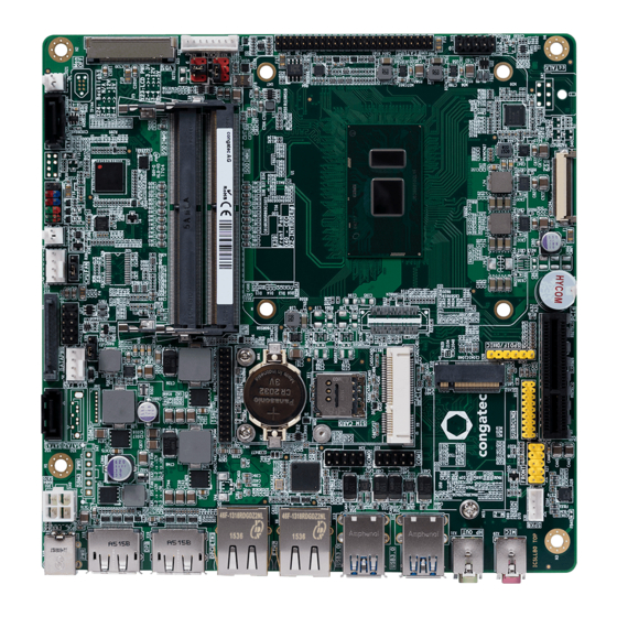
- Page 1 Thin Mini-ITX SBC Detailed Description Of The congatec Thin Mini-ITX Based On 7th Generation Intel U-Series SoC User's Guide Revision 0.2 (Preliminary)
-
Page 2: Revision History
Revision Date (yyyy.mm.dd) Author Changes 2017.01.18 • Preliminary release 2017.12.05 • Updated section 5.8.1 “Standard SATA Connectors” • Updated table 43 “Feature Connector X38 Pinout Description” • Added content to section 8 “BIOS Setup Description” Copyright © 2017 congatec AG ICKLm02 2/59... -
Page 3: Intended Audience
In no event shall congatec AG be liable for any incidental, consequential, special, or exemplary damages, whether based on tort, contract or otherwise, arising out of or in connection with this user’s guide or any other information... -
Page 4: Copyright Notice
Copyright © 2017, congatec AG. All rights reserved. All text, pictures and graphics are protected by copyrights. No copying is permitted without written permission from congatec AG. congatec AG has made every attempt to ensure that the information in this document is accurate yet the information contained within is supplied “as-is”. - Page 5 (c) arising from course of performance, course of dealing, or usage of trade. congatec AG shall in no event be liable to the end user for collateral or consequential damages of any kind. congatec shall not otherwise be liable for loss, damage or expense directly or indirectly arising from the use of the product or from any other cause.
-
Page 6: Technical Support
Technical Support congatec AG technicians and engineers are committed to providing the best possible technical support for our customers so that our products can be easily used and implemented. We request that you first visit our website at www.congatec.com for the latest documentation, utilities and drivers, which have been made available to assist you. -
Page 7: Table Of Contents
Micro-SIM Card ................ 48 5.3.2.1 Stereo Speaker Header ............28 Micro-SD Card ................. 49 5.3.2.2 Digital Microphone/SPDIF ............28 MIPI CSI-2 ................50 5.3.2.3 Front Panel (HD Audio/AC97) ..........29 Integrated Sensor Hub ............. 51 Copyright © 2017 congatec AG ICKLm02 7/59... - Page 8 6.11 Beeper ..................54 Trusted Platform Module – TPM (Optional) ......52 6.12 External System Wake Event ........... 55 congatec Board Controller (cBC) ..........52 6.13 Feature Connector ..............55 6.8.1 Fan Control ................52 conga-IC175 Mechanical Drawing ........... 57 6.8.2...
- Page 9 List of Tables Table 1 conga-IC175 Variants ............... 11 Table 37 Front Panel (Connector X39) Pinout Description ..... 48 Table 2 Cooling/IO Shield ..............11 Table 38 Connector X11 Pinout Description .......... 48 Table 3 Memory Modules ..............11 Table 39 Connector X60 Pinout Description ..........
-
Page 10: Introduction
With smaller board size and lower height keep-out zones, the conga-IC175 SBC provides manufacturers and system designers with the opportunity to design compact systems for space restricted areas. With appropriate I/O shield, the same conga-IC175 SBC can be used in either a Thin Mini-ITX or a Mini-ITX design. -
Page 11: Options Information
Table 2 Cooling/IO Shield Accessories Part No. Description conga-IC97/CSA 052252 12 V active cooling solution with Thin Mini-ITX height (compatible with conga-IC175) conga-IC97/Retention Frame 052254 Retention frame for conga-IC97/CSA (compatible with conga-IC175) conga-IC97/CSP 052260 Passive cooling solution with Thin Mini-ITX height (compatible with conga-IC175) -
Page 12: Table 4 Cables
052232 eDP to standard HDMI evalutiona adapter conga-Thin MITX/LVDS Adapter 052233 LVDS pin header evaluation adapter for congatec Thin Mini-ITX boards conga-Thin MITX/Debug Card 047858 Evaluation debug card with post code display, buttons, status LED's and other useful IO's conga-DP2VGA... -
Page 13: Table 7 2.5-Inch Ssds
2.5" SSD, 128 GB SATA III – Innodisk 3ME3 series 10000205 SATA III (6 Gbps), 15 nm, MLC, 0°C to 70°C 2.5" SSD, 256 GB SATA III – Innodisk 3ME3 series 10000206 SATA III (6 Gbps), 15 nm, MLC, 0°C to 70°C Copyright © 2017 congatec AG ICKLm02 13/59... -
Page 14: Specification
Core™ i7,i5, i3 and Celeron Single Chip Ultra Low TDP Processors ® Memory Two memory sockets (located on the top side of the conga-IC175). Supports SO-DIMM non-ECC DDR4 modules Data rates up to 2133 MT/s Maximum 32 GB capacity (16 GB each) -
Page 15: Supported Operating Systems
Thermal and voltage monitoring CMOS Battery Beeper congatec standard BIOS (also possible to boot from an external BIOS by triggering the BIOS_DISABLE# signal on the feature connector) BIOS AMI Aptio UEFI 5.x firmware, 8/16 MByte serial SPI with congatec Embedded BIOS features. -
Page 16: Supply Voltage Power
The power consumption values were measured using the following test setup: • Input voltage +12V • conga-IC175 SBC • conga-IC175 cooling solution • Microsoft Windows 10 (64 bit) Note The CPU was stressed to its maximum workload with the Intel Thermal Analysis Tool. -
Page 17: Supply Voltage Battery Power
Table 10 Power Consumption Values The tables below provide additional information about the power consumption data for each of the conga-IC175 variants offered. The values are recorded at various operating mode. Part Memory BIOS OS (64 bit) Current (Amp.) Size Rev. -
Page 18: Environmental Specifications
Operation: 0° to 60°C Storage: -20° to +70°C Humidity Operation: 10% to 90% Storage: 5% to 95% Note The above operating temperatures must be strictly adhered to at all times. Humidity specifications are for non-condensing conditions. Copyright © 2017 congatec AG ICKLm02 18/59... -
Page 19: Block Diagram
Optional feature (available with a customized variant) SATA 2 * Connected either to a standard SATA connector or to an Power IN M.2 slot. SATA Power Supports GPIOs, SPI, SMBus, LPC, UART, I2C, Sleep, LID, Watchdog Copyright © 2017 congatec AG ICKLm02 19/59... -
Page 20: Cooling Solution
Nonetheless, all electronics contain semiconductor devices which have operating temperature ranges that should be adhered to. For this reason, it is imperative to provide sufficient air flow to each of the components, to ensure the specified operating temperature of the conga-IC175 is maintained. -
Page 21: Cooling Installation
• Connect the fan’s power cable. Caution The congatec heatspreaders/cooling solutions are tested only within the commercial temperature range of 0° to 60°C. Therefore, if your application that features a congatec heatspreader/cooling solution operates outside this temperature range, ensure the correct operating temperature of the module is maintained at all times. -
Page 22: Active Cooling Dimensions
All measurements are in millimeters. Torque specification for cooling solution screws is 0.6 Nm. Mechanical system assembly mounting shall follow the valid DIN/IS0 specifications. To replace the fan, use equivalent fan with similar parameters. Copyright © 2017 congatec AG ICKLm02 22/59... -
Page 23: Connector Description
Connector Description Power Supply You can power the conga-IC175 SBC with a 12V – 24V laptop type DC power supply (on connector X48) or a 4-pin internal power supply (on connector X49). Additionally, the SBC offers an optional SBM power connector (only BOM option). When this connector (X47) is populated, you can power the SBC with it. -
Page 24: Power Supply (Internal Connector)
X49 : 2x2-pin, 4.2 mm pitch connector Mating connector: Molex 87427-0442 Note The conga-IC175 turns on immediately you connect a power supply. To change this behavior, set the “Power Loss Control” in the BIOS Boot Settings Configuration menu to “Remain OFF”. 5.1.3... -
Page 25: Optional Sbm3 Signal Connector
Optional SBM3 Signal Connector As mentioned in section 5.1.3, you need the optional power connector X47 and the signal connector X47 for designs with SBM battery kit. The signal connector ensures the conga-IC175 communicates flawlessly with the battery kit. Table 15... -
Page 26: Power Status Leds
5.1.4 Power Status LEDs The conga-IC175 provides two LED signals (FP_LED+ and P_LED-) on pins 2 and 4 of the front panel connector X39. The signals indicate the different power states of the conga-IC175. Table 16 LED States State FP_LED+... -
Page 27: Audio Interface
Rear Audio Connectors The conga-IC175 has a high definition audio codec (Realtek ALC888S) mounted on it. The line output signals and the MIC signals are routed to connectors X31 (Line-OUT) and X29 (MIC-IN) on the rear side respectively. You can find the drivers for this codec at: http://www.congatec.com/en/products/mini-itx-single-board-computer/conga-ic175.html... -
Page 28: Internal Audio Connectors
5.3.2 Internal Audio Connectors The conga-IC175 provides the stereo speaker, digital microphone/SPDIF, front panel HD and surround audio connectors internally. 5.3.2.1 Stereo Speaker Header The first analog line input channels (left and right) of the Realtek ALC888S HDA audio codec are routed to connector X30, via a TPA2012D2 amplifier. -
Page 29: Front Panel (Hd Audio/Ac97)
Microphone jack detection Pin 1 SENSE Jack detection for HDA codec No pin LINE2_L 2nd analog line output - left channel (headphone) LINE2_JD Line output jack detection Connector Type X27: 2.54 mm, 2x5-pin header Copyright © 2017 congatec AG ICKLm02 29/59... -
Page 30: Surround Header
The SPI signals are connected to the onboard SPI flash and the feature connector (X38). With the SPI signals on the feature connector, you can start the conga-IC175 from an external flash. This however requires a customized adapter to trigger the BIOS_DISABLE# signal (pin 46) of the feature connector. -
Page 31: I²C Bus
(X38) described in section 6.13 of this document. LPC Super I/O Device The conga-IC175 has an onboard Super I/O controller. The controller is connected to the SoC’s LPC bus and provides additional interfaces such as two serial interfaces, optional ccTALK, GPOs, 4-wire CPU and system fans. . -
Page 32: Cpu/System Fan Connector & Power Configuration
CPU/System Fan Connector & Power Configuration The conga-IC175 supports 5V or 12V CPU and system fans. The signals of the CPU and system fans are routed to connectors X33 and X36 respectively. Use jumper X32 to select the voltage of the CPU fan and jumper X35 to select the voltage of the system fan. -
Page 33: Universal Serial Bus (Usb)
5.6.1 Rear USB Connectors The conga-IC175 offers four USB 3.0 ports (port 1-4) on the rear side. These ports are routed directly from the SoC to connectors X13 and X14. The ports support also USB 2.0 devices. USB Port 2... -
Page 34: Internal Usb Connectors
5.6.2 Internal USB Connectors The conga-IC175 offers four USB ports (ports 7-10) internally. Ports 7 and 8 are routed to connector X16 while ports 9 and 10 are routed to connector X15. Table 24 Connector X16 Pinout Description Internal USB - Connector X16... -
Page 35: Ethernet 10/100/1000
Ethernet 10/100/1000 The conga-IC175 provides two Gigabit Ethernet ports (connectors X5 and X6) on the rear side. Only the LAN interface on connector X5 supports Intel AMT technology. Connector X5/X6 Table 26 LED Description LED Left Side Description LED Right Side Description... -
Page 36: Sata Power
3. Connector X52 supports SATADOM devices on hardware revision A.x and later. 5.8.2 SATA Power The conga-IC175 provides an internal SATA power for hard drives on connector X12. This connector supplies 3.3V, 5V and 12V. Table 27 Connector X12 Pinout Description. -
Page 37: M.2 Slot
5.8.3 M.2 Slot The conga-IC175 offers an M.2, type 3042/2242 slot (X10) for connecting SATA or PCIe x2 SSDs and WWAN devices. Table 28 Connector X10 Pinout Description (Revision B.x and later) Pin Signal Pin Signal CONFIG_3 +3.3V +3.3V FULL_CARD_PWROFF# M.2 Type B Slot - Connector X10... - Page 38 1. On hardware revision A.x and earlier, the M.2 slot supports SATA SSD and WWAN (USB 2.0) devices by default, and PCIe x1 devices via a customized BIOS. 2. Micro-SIM card slot (connector 11) is connected to the UIM Interface of the M.2 slot by default. Copyright © 2017 congatec AG ICKLm02 38/59...
-
Page 39: Display Interfaces
LVDS The conga-IC175 offers LVDS interface on connector X25 – a 40-pin LVDS connector. The LVDS signals are sourced from incoming eDP stream, via a multiplexer. The multiplexer routes the eDP signals to LVDS connector X25 (via an eDP to LVDS bridge) by default. -
Page 40: Table 29 Connector X25 Pinout Description
Note 1. The maximum output current for LCD and backlight power rails is 2A. 2. congatec offers cables and adapter for the LVDS interface (see section 1.2.2 “Optional Accessories/Cables”). For more information, contact congatec technical solution department. Copyright © 2017 congatec AG... -
Page 41: Embedded Display Port (Edp)
Embedded Display Port (eDP) The conga-IC175 provides eDP interface on connector X20 - a standard 40-pin DisplayPort connector. The eDP signals are sourced from incoming eDP stream via a multiplexer. The multiplexer routes the eDP signals to LVDS connector X25 (via an eDP to LVDS bridge) by default. -
Page 42: Backlight Power Connector
Mating connector: ACES 88441-40 or ACES 50204-40 Note congatec offers cables and adapter for the eDP interface (see section 1.2.2 “Optional Accessories/Cables”). For more information, contact the congatec technical solution department. 5.9.3.1 Backlight Power Connector The conga-IC175 provides backlight power on connector X22. -
Page 43: Backlight/Panel Power Selection
Backlight/Panel Power Selection The conga-IC175 supports different voltages for the panel and backlight. With jumper X23, you can set the panel voltage to 3,3V, 5V or 12V. With jumper X24, you can set the backlight voltage to 5V or 12V. -
Page 44: Pci Express
5.9.4 PCI Express The conga-IC175 provides 3 PCIe interfaces - a PCIe M.2 slot on connector X10 (see section 5.8.3), a PCIe x4 slot on connector X7 and a full/ half size mini PCIe slot on connector X8 5.9.4.1 PCIe x4 Slot The conga-IC175 offers a PCIe x4 slot on connector X7. -
Page 45: Full/Half-Size Mini Pcie
Full/half-size Mini PCIe The conga-IC175 offers a mini PCIe socket on connector X8. This socket is optimized for mobile computing platforms and provides the ability to insert different removable mini PCIe cards. This approach makes it possible to upgrade standard PCIe mini card devices on the SBC, without extra cost of a redesign. - Page 46 USB_D+ +3.3V +3.3V LED_WLAN# (optional) CL_CLK CL_DATA +1.5V CL_RST# +3.3V Connector Type X8: PCIe mini card socket Note The micro-SIM card slot (connector X11) can optionally be connected to these pins (UIM interface). Copyright © 2017 congatec AG ICKLm02 46/59...
-
Page 47: Pci Express Routing
Slot 0 PCIe Lane1 PCIe Lane2 PCIe Lane3 PCIe Lane4 Mini PCIe Slot 1 PCIe Lane9 USB 2.0 Signals M.2 Connector Slot 2 PCIe Lane11 PCIe Lane12 or SATA port 2 USB 2.0 Signals Copyright © 2017 congatec AG ICKLm02 47/59... -
Page 48: Additional Features
Front Panel Connector The conga-IC175 SBC supports front panel features such as power button, status LEDs and reset button via connector X39 - a 10-pin internal header. The FP_LED+ and FP_LED- signals communicate the system states to two LEDs connected to this header. See section 5.1.5 “Power Status LED”... -
Page 49: Micro-Sd Card
2. The slot can optionally be connected to the UIM interface of the mPCIe slot. Micro-SD Card The conga-IC175 offers a micro-SD slot on connector X60. The SD card slot complies with SDXC card specification 3.0 with support for up to 104 MBps data rate. -
Page 50: Mipi Csi-2
MIPI CSI-2 The conga-IC175 offers an onboard camera interface on connector X9. The interface supports up to two independent cameras - four data lanes for the first camera and two data lanes for the second camera. Each lane operates at up to 1.5 Gbps depending on the camera’s resolution. It also supports up to 24 MP image capture @ 15fps, full HD 1080p60. -
Page 51: Integrated Sensor Hub
GPIO for Camera 1 (1.8V) Connector Type X9: 36-pin, 0.5 mm pitch flat-foil connector Integrated Sensor Hub The conga-IC175 offers an Integrated Sensor Hub (ISH) on connector X61. ISH - Connector X61 Table 41 ISH (Connector X61) Pinout Description Pin 1... -
Page 52: Case Open Intrusion Connector
X2: 2.54 mm, 2-pin Molex KK series connector Trusted Platform Module – TPM (Optional) The conga-IC175 SBC can be equipped optionally with a TPM 2.0 compliant security chip. The chip is connected to the LPC bus provided by the integrated Intel chipset. -
Page 53: Power Loss Control
OEM BIOS Code With the congatec embedded BIOS it is even possible for system designers to add their own code to the BIOS POST process. Except for custom specific code, this feature can also be used to support Window 7 SLIC table, verb tables for HDA codecs, rare graphic modes and Super I/O controllers. -
Page 54: Congatec Battery Management Interface
The CGOS API (congatec Operating System Application Programming Interface) is the congatec proprietary API that is available for all commonly used Operating Systems such as Win32, Win64, Win CE and Linux. -
Page 55: External System Wake Event
The conga-IC175 supports LAN, USB, PCIe and PWRBTN driven wake up events. 6.13 Feature Connector The conga-IC175 provides an internal 50-pin, 2mm pin header as feature connector. The pinout is described below: Table 43 Feature Connector X38 Pinout Description Feature Connector X38... - Page 56 GPI0 Input 3.3V PU 10k General purpose input to Board controller GPI1 Input 3.3V PU 10k General purpose input to congatec Board controller GPI2 Input 3.3V PU 10k General purpose input to congatec Board controller GPI3 Input 3.3V PU 10k...
-
Page 57: Conga-Ic175 Mechanical Drawing
Mechanical Drawing LVDS BACKLIGHT FEATURE CONNECTOR 2x USB 2.0 HEADER Bklt Power Power SPDIF/DMIC SIM CARD SATA2 SATA1 COM0 COM1 DP++ DP++ ETH1 ETH2 USB3.0 USB3.0 LINE OUT 6.35 23.2 8.06 98.2 104.7 163.83 Copyright © 2017 congatec AG ICKLm02 57/59... -
Page 58: Bios Setup Description
OEMs often use BIOS updates to correct platform issues discovered after the board has been shipped or when new features are added to the BIOS. The conga-IC175 uses a congatec/AMI AptioEFI firmware, which is stored in an onboard flash ROM chip and can be updated using the congatec System Utility. -
Page 59: Industry Specifications
Industry Specifications The list below provides links to industry specifications that apply to congatec AG modules. Specification Link Low Pin Count Interface Specification, Revision 1.0 (LPC) http://developer.intel.com/design/chipsets/industry/lpc.htm Universal Serial Bus (USB) Specification, Revision 2.0 http://www.usb.org/home PCI Specification, Revision 2.3 http://www.pcisig.com/specifications Serial ATA Specification, Revision 3.0...
Need help?
Do you have a question about the conga-IC175 and is the answer not in the manual?
Questions and answers