
Related Manuals for Congatec conga-IA5


Summary of Contents for Congatec conga-IA5
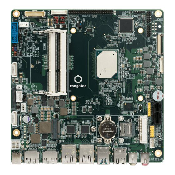
- Page 1 Thin Mini-ITX SBC Detailed Description Of The congatec Thin Mini-ITX Based On Intel® Apollo Lake SoCs User's Guide Revision 1.0...
-
Page 2: Revision History
2017.07.19 • Preliminary release • Updated image of the conga-IA5 on the title page • Removed Android from supported OS in section 2.2 "Supported Operating Systems" • Added power consumption values in section 2.5 "Power Consumption" and 2.6 "Supply Voltage Battery Power"... -
Page 3: Intended Audience
In no event shall congatec AG be liable for any incidental, consequential, special, or exemplary damages, whether based on tort, contract or otherwise, arising out of or in connection with this user’s guide or any other information... -
Page 4: Copyright Notice
Copyright © 2017, congatec AG. All rights reserved. All text, pictures and graphics are protected by copyrights. No copying is permitted without written permission from congatec AG. congatec AG has made every attempt to ensure that the information in this document is accurate, yet the information contained within is supplied “as-is”. - Page 5 (c) arising from course of performance, course of dealing, or usage of trade. congatec AG shall in no event be liable to the end user for collateral or consequential damages of any kind. congatec shall not otherwise be liable for loss, damage or expense directly or indirectly arising from the use of the product or from any other cause.
-
Page 6: Technical Support
Technical Support congatec AG technicians and engineers are committed to providing the best possible technical support for our customers so that our products can be easily used and implemented. We request that you first visit our website at www.congatec.com for the latest documentation, utilities and drivers, which have been made available to assist you. -
Page 7: Table Of Contents
Digital Microphone and S/PDIF Header ........27 Chassis Intrusion Header ............50 5.2.5 Front Panel Audio Header ............28 Security Features ..............51 Communication Bus ..............29 congatec Board Controller (cBC) ..........51 Copyright © 2017 congatec AG IA50m10 7/59... - Page 8 6.4.3 Board Information ..............52 6.11 Feature Connector ..............55 6.4.4 GPIOs ..................52 conga-IA5 Mechanical Drawing ..........57 OEM BIOS Customization ............52 6.5.1 OEM Default Settings .............. 52 BIOS Setup Description ............58 6.5.2 OEM Boot Logo ............... 52 Navigating the BIOS Setup Menu ...........
- Page 9 List of Tables Table 1 conga-IA5 Commercial Variants ..........11 Table 37 X28 Pinout Description ............44 Table 2 conga-IA5 Industrial Variants ........... 11 Table 38 X8 Pinout Description .............. 44 Table 3 Cooling/IO Shield ..............12 Table 39 X9 Pinout Description .............. 45 Table 4 Memory Modules ..............
-
Page 10: Introduction
With smaller board size and lower height keep-out zones, the conga-IA5 SBC provides manufacturers and enthusiasts with the opportunity to design compact systems for space restricted areas. With appropriate I/O shield, the same conga-IA5 SBC can be used in either a Thin Mini-ITX or a Mini-ITX design. -
Page 11: Options Information
1.2.1 Options Information The conga-IA5 is currently available in six variants. This user’s guide describes all of these variants. The tables below show the different configurations available. Check for the Part No. that applies to your product. This will tell you what options described in this user’s guide are available on your particular module. -
Page 12: Optional Accessories
Part No. Description conga-Thin MITX/eDP to DP Adapter 052231 eDP to standard DisplayPort evaluation adapter for congatec Thin Mini-ITX boards conga-Thin MITX/eDP to HDMI Adapter 052232 eDP to standard HDMI evaluation adapter for congatec Thin Mini-ITX boards Copyright © 2017 congatec AG... -
Page 13: Specification
Ultra low standby power consumption, Deep Sx Other Features Thermal and voltage monitoring, CMOS Battery, Beeper congatec Standard BIOS (also possible to boot from an external BIOS by triggering the BIOS_DISABLE# signal on the feature connector) Security Integrated Intel ®... -
Page 14: Supported Operating Systems
• Yocto Note To install Microsoft ® Windows ® 10 (64-bit), we recommend a minimum storage capacity of 20 GB. congatec will not offer support for systems with less than 20 GB storage space. Copyright © 2017 congatec AG IA50m10 14/59... -
Page 15: Mechanical Dimensions
Caution The absolute maximum rating of the input voltage is 36 volts. Do not exceed this rating or expose the conga-IA5 to the absolute maximum voltage for a prolonged time. Doing so may damage the system or affect system reliability. -
Page 16: Table 8 Measurement Description
The fan and SATA drives were powered externally. All other peripherals, except the LCD monitor, were disconnected before measurement. Table 9 Power Consumption Values The tables below provide additional information about the power consumption data for each of the conga-IA5 variants offered. The values are recorded at various operating modes. Part... -
Page 17: Supply Voltage Battery Power
Storage: 5% to 95% Caution The above operating temperatures must be strictly adhered to at all times. When using a congatec heatspreader, the maximum operating temperature refers to any measurable spot on the heatspreader’s surface. Humidity specifications are for non-condensing conditions. -
Page 18: Block Diagram
USB 3.0 2x USB 2.0 HD Audio Front Panel High Definition Audio CS4207 HD Audio DMIC LVDS eDP to LVDS Audio HeadPh Backlight Power External I/O Internal I/O optional Audio MIC Panel Power Monitor Copyright © 2017 congatec AG IA50m10 18/59... -
Page 19: Cooling Solution
Nonetheless, all electronics contain semiconductor devices which have operating temperature ranges that should be adhered to. This means that for reliable operation, the thermal design of the conga-IA5 must be carefully considered. For this reason, it is imperative to provide sufficient air flow to each of the components, to ensure the specified operating temperature of the conga-IA5 is maintained. -
Page 20: Cooling Installation
For applications that require vertically-mounted CSP, use only cooling solution that secure the thermal stacks with fixing post. Without the fixing post feature, the thermal stacks may move. Also, do not exceed the maximum torque specification for the cooling solution screws. Doing so may damage the SBC. Copyright © 2017 congatec AG IA50m10 20/59... -
Page 21: Csp Dimensions
Lidless Die Variants (PN: 052830) ® ® 21.2 19.75 Note All measurements are in millimeters. Recommended maximum torque for cooling solution screws is 0.3 Nm. Mechanical system assembly mounting shall follow the valid DIN/IS0 specifications. Copyright © 2017 congatec AG IA50m10 21/59... - Page 22 Atom™ Lidded Die Variants (PN: 052831) 21.2 19.75 Note All measurements are in millimeters. Recommended maximum torque for cooling solution screws is 0.3 Nm. Mechanical system assembly mounting shall follow the valid DIN/IS0 specifications. Copyright © 2017 congatec AG IA50m10 22/59...
-
Page 23: Connector Description
X43: DC power jack, 7.4x5.1mm (Singatron 2DC1003-000111) 5.1.2 ATX 4-Pin Connector The conga-IA5 offers a straight 4-pin power connector (X44). Optionally, a right angle 4-pin power connector (X48) can be placed instead. The supported power supply is defined in section 2.4 “Supply Voltage Power”. Table 12... -
Page 24: Sbm 3 Connectors
X48: 2x2 pins, 4.2mm pitch (PN: 41500604) 5.1.3 Connectors Optionally, the conga-IA5 provides connectors for SBM (X45, X46). Connect the data control cable to header X45. Connect the power cable to connector X46. The supported power supply is defined in section 2.4 “Supply Voltage Power”. -
Page 25: Pwr_Ok Signal
The SBC then begins its onboard power-up sequence. 5.1.5 Power Status LEDs The conga-IA5 provides two LED signals (FP_LED+ and P_LED-) on pins 2 and 4 of the front panel connector X39. The signals indicate the different power states of the conga-IA5. Table 16... -
Page 26: Audio Connectors
Audio Connectors The audio signals of the following connectors are routed from a high definition audio (HDA) codec (Cirrus Logic CS4207). 5.2.1 Microphone Jack The conga-IA5 provides a microphone jack (X20). Table 18 X20 Pinout Description Signal Description MIC1_L 1st Stereo microphone analog input left channel... -
Page 27: Stereo Speakers Header
5.2.3 Stereo Speakers Header The conga-IA5 provides a stereo speakers header (X21). The signals are amplified (TI TPA2012D2), providing 2x 2.1W into 4ohm at 5V. Table 20 X21 Pinout Description Signal Description OUTL- Left channel negative differential output OUTL+ Left channel positive differential output... -
Page 28: Front Panel Audio Header
5.2.5 Front Panel Audio Header The conga-IA5 provides a front panel audio header (X18). Table 22 X18 Pinout Description Signal Description MIC2_L 2nd Analog stereo microphone input—left channel No Pin Ground Pin 10 MIC2_R 2nd Analog stereo microphone input—right channel... -
Page 29: Communication Bus
The conga-IA5 supports both SMBus and I C compliant devices. 5.3.1 SMBus The SMBus signals are available in different locations on the conga-IA5, including the feature connector (X35) described in section 6.11 of this document. 5.3.2 I²C Bus The congatec Board controller provides I²C signals. These signals are available in different locations on the conga-IA5, including the feature connector (X35) described in section 6.11 of this document. -
Page 30: Uart Headers
UART Headers The conga-IA5 provides two UART headers (X24, X25) via a Super IO (NCT6102D). The UART ports can be used under Windows 10 and Linux without a special driver. UART header X24 (COM 0) fully supports RS-232. UART header X25 (COM 1) supports RS232 (Rx and Tx only), RS422 and RS485. -
Page 31: Cpu And System Fan Header
5.4.2 CPU and System Fan Header The conga-IA5 provides a CPU fan header (X36) and system fan header (X38). Use jumper X36 to select the CPU fan voltage. Use jumper X38 to select the system fan voltage. Table 25 X36 Pinout Description... -
Page 32: Universal Serial Bus (Usb)
Universal Serial Bus (USB) The conga-IA5 provides six USB ports. All USB ports are routed directly from the SoC. Apollo Lake SoC USB3_P2 to M.2 Connector USB2_P7 to M.2 Connector USB3 to mPCIe Connector 2x USB 2.0 Rear Ports 2x USB 3.0/2.0 Rear Ports 1x USB 3.0/2.0 Internal Port... -
Page 33: Usb 2.0 Ports
5.5.1 USB 2.0 Ports The conga-IA5 provides two USB 2.0 ports (X16) and two USB 3.0 ports (X17). Connector Type Upper Upper X16, X17: Two type A, dual port USB connectors Lower Lower Note The USB 2.0 ports have a maximum current of 0.5A. The USB 3.0 ports have a maximum current of 1.0A. -
Page 34: Usb 2.0 Header
Connector Type X15: 5x1 pins, 2.54mm pitch Note The maximum current is 0.5A. congatec offers a cable for connector X15 (see section 1.2.2 “Optional Accessories"). For more information, contact congatec technical solution department. Caution The maximum cable length of a USB 2.0 device connected to this header shall not exceed 3 meters in order to comply to EN 55024:2010. -
Page 35: Gigabit Ethernet Ports
Gigabit Ethernet Ports The conga-IA5 provides two Gigabit Ethernet ports (connectors X6 and X7) on the rear side. The two Gigabit Ethernet interfaces are supported via the Intel Gigabit Ethernet controller i211 (commercial variants) or i210 (industrial variants). Table 30... -
Page 36: Sata / Satadom Ports
SATA / SATADOM Ports The conga-IA5 provides two SATA 6Gb/s ports (CN1, CN2). You can enable SATADOM on SATA port 0 (CN1) in BIOS setup. The SATA port 1 (CN2) is shared with M.2 card slot (X12). You can switch the SATA1 signals to either the SATA port 1 (CN2) or the M.2 card slot (X12) in BIOS setup. -
Page 37: M.2 3042/2242 Card Slot
M.2 3042/2242 Card Slot The conga-IA5 provides an M.2 3042/2242 card slot (X12) for connecting a SATA or PCIe SSD and WWAN device. This connector shares the SoC's SATA1 signals with CN2. You can have either SATA1 (default) or PCIe4 signals on the M.2 slot (X12). You can change the signals to PCIe4 in the BIOS setup. - Page 38 +3.3V +3.3V CONFIG_2 Connector Type X12: M.2 type B slot (compatible with card size 3042 or 2242) Note Optionally, the micro-SIM card slot (connector X10) can be connected to the M.2 socket instead. Copyright © 2017 congatec AG IA50m10 38/59...
-
Page 39: Display Interfaces
Display Interfaces The conga-IA5 supports three simultaneous displays—two DP++ and an LVDS or eDP displays. 5.8.1 DP++ Ports The conga-IA5 SBC provides two DP++ ports (X26, X27), supporting DP, HDMI and DVI displays. X26, X27 Connector Type X26, X27: Dual DisplayPort Note HDMI and DVI require an external passive cable adapter. -
Page 40: Lvds Header
LVDS Header The conga-IA5 offers an LVDS header (X33). The LVDS signals are sourced from the SoC's DDI stream via a multiplexer. The header supports 24-bit dual channel, selectable backlight voltage, VESA color mappings, automatic panel detection and up to 1920x1200 resolution. -
Page 41: Edp Connector
5.8.3 eDP Connector The conga-IA5 provides an eDP connector (X29). In order to use it, change the "Active LFP Configuration" in the BIOS setup menu to "eDP". Table 33 X29 Pinout Description Signal Signal VCC_LCD eDP_TX3- eDP_TX3+ eDP_TX2- eDP_TX2+ eDP_HPD... -
Page 42: Backlight Power Header
5.8.3.1 Backlight Power Header The conga-IA5 provides a backlight power header (X32). The power budget of BKLT_PWR (pins 3 and 4) is limited to 1.5A. Table 34 X32 Pinout Description Signal Name Description LVDS_BKLT_EN Backlight enable Pin 1 LVDS_BKLT_CTRL Backlight control... -
Page 43: Backlight/Panel Power Selection
Backlight/Panel Power Selection The conga-IA5 supports different voltages for the panel and backlight connectors. With jumper X31, you can set the backlight voltage to 5V or 12V. With jumper X30, you can set the panel voltage to 3.3V, 5V or 12V. -
Page 44: Monitor Off Header
X28: 2x1 pins, 2.54mm pitch PCI Express Connectors The conga-IA5 provides a PCIe x1 card slot, a mini PCIe card slot (half-size ) and a mini PCIe (full-size) card slot. You can use either the mini PCIe half-size or full-size card slot. -
Page 45: Mini Pcie Card Slot (Half-Size)
You can use either the PCIe x1 (X8) or mPCIe slot (X9). The PCIe x1 slot (x8) will not function if you insert a card into the mPCIe slot (X9). 5.9.2 Mini PCIe Card Slot (Half-Size) The conga-IA5 provides a mini PCIe slot (X9) for a half size card. Table 39 X9 Pinout Description... - Page 46 Signal Signal N.C. W_DISABLE# PERST# PERn0 +3.3Vaux PERp0 +1.5V SMB_CLK PETn0 SMB_DATA PETp0 USB_D- USB_D+ +3.3Vaux +3.3Vaux mSATA_mPCIe_detect CL_CLK CL_DATA +1.5V CL_RST# N.C. +3.3Vaux Connector Type X9: Mini PCIe card slot (half-size) Copyright © 2017 congatec AG IA50m10 46/59...
-
Page 47: Mini Pcie Card Slot (Full-Size)
5.9.3 Mini PCIe Card Slot (Full-Size) The conga-IA5 provides a mini PCIe slot (X9) for a full-size card. This connector shares the SoC's PCIe 2 signals with connector X8 (PCIe x1 slot), via a multiplexer. When an mPCIe device is attached to the mPCIe slot (connector X9), the SoC automatically detects the type of device that is attached (via pin 43—the signal detect pin). -
Page 48: Micro-Sim Card Slot
5.10 Micro-SIM Card Slot The conga-IA5 provides a micro-SIM card slot (X10) connected to the UIM interface of the mPCIe slot by default. Table 40 X10 Pinout Description Signal Description Power Reset Clock Not available Ground Programming voltage input Data... -
Page 49: Pci Express Routing
You can have either USB3.0 (default) or PCIe5 signals on the M.2 slot (X12). You can change the signals to PCIe5 with a custom BIOS. You can have either SATA1 (default) or PCIe4 signals on the M.2 slot (X12). You can change the signals to PCIe4 in the BIOS setup. Copyright © 2017 congatec AG IA50m10... -
Page 50: Additional Features
Additional Features Front Panel Header The conga-IA5 provides a front panel header (X39). Table 41 X39 Pinout Description Function Description HDD_POWER_LED+ Hard disk power LED with pull-up resistor to 3.3V. No Pin FP_LED+ Power LED (main color) SATA_ACT# Hard disk activity LED... -
Page 51: Security Features
The conga-IA5 is equipped with a Texas Instruments Tiva™ TM4E1231H6ZRBI microcontroller. This onboard microcontroller plays an important role for most of the congatec BIOS features. It fully isolates some of the embedded features such as system monitoring or the I²C bus from the x86 core architecture, which results in higher embedded feature performance and more reliability, even when the x86 processor is in a low power mode. -
Page 52: Board Information
OEM POST Logo This feature allows system designers to replace the congatec POST logo displayed in the upper left corner of the screen during BIOS POST with their own BIOS POST logo. Use the congatec system utility CGUTIL 1.5.4 or later to replace/add the OEM POST logo. -
Page 53: Oem Bios Code / Data
OEM BIOS Code / Data With the congatec embedded BIOS, it is possible for system designers to add their own code to the BIOS POST process. The congatec Embedded BIOS first calls the OEM code before handing over control to the OS loader. -
Page 54: Api Support (Cgos)
The architecture of the CGOS API driver provides the ability to write application software that runs unmodified on all congatec CPU modules. All the hardware related code is contained within the congatec embedded BIOS on the module. See section 1.1 of the CGOS API software developers guide, which is available on the congatec website. -
Page 55: Feature Connector
6.11 Feature Connector The conga-IA5 provides a feature connector (X35). Table 43 X35 Pinout Description Signal name Pin Type Voltage Onboard Description level termination Power +5V runtime power output, 500mA max. Ground LAD0 3.3V LPC command, address, data 0 LAD1 3.3V... - Page 56 3.3V standby external SPI flash clock input SPI_MOSI_EXT Output 3.3V standby external SPI flash data input +5V standby Power 5V standby +5V standby power, 500mA max. Ground Connector Type X35: 25x2 pins, 2mm pitch Copyright © 2017 congatec AG IA50m10 56/59...
-
Page 57: Conga-Ia5 Mechanical Drawing
Mechanical Drawing Copyright © 2017 congatec AG IA50m10 57/59... -
Page 58: Bios Setup Description
OEMs often use BIOS updates to correct platform issues discovered after the board has been shipped or when new features are added to the BIOS. The conga-IA5 uses a congatec/AMI AptioEFI firmware, which is stored in an onboard flash ROM chip and can be updated using the congatec System Utility. -
Page 59: Industry Specifications
Industry Specifications The list below provides links to industry specifications that apply to congatec AG modules. Specification Link Low Pin Count Interface Specification, Revision 1.0 (LPC) http://developer.intel.com/design/chipsets/industry/lpc.htm Universal Serial Bus (USB) Specification, Revision 2.0 http://www.usb.org/home PCI Specification, Revision 2.3 http://www.pcisig.com/specifications Serial ATA Specification, Revision 3.0...
Need help?
Do you have a question about the conga-IA5 and is the answer not in the manual?
Questions and answers