
Related Manuals for Congatec Qseven conga-QA5


Summary of Contents for Congatec Qseven conga-QA5
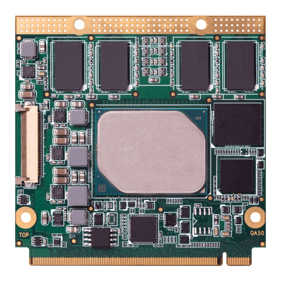
- Page 1 Qseven conga-QA5 ® Qseven module based on the Intel® Atom™, Pentium® and Celeron® Apollo Lake SoC User’s Guide Revision 1.0...
-
Page 2: Revision History
Descriptions", table 22 "LPC Signal Descriptions", and table 28 "Miscellaneous Signal Descriptions" • Added inrush current in section 5.12 "Power Control" • Added section 5.15 "MIPI CSI-2" • Added information to section 9 "System Resources" • Added information to section 10 "BIOS Setup Description" Copyright © 2017 congatec AG QA50m10 2/61... -
Page 3: Intended Audience
In no event shall congatec AG be liable for any incidental, consequential, special, or exemplary damages, whether based on tort, contract or otherwise, arising out of or in connection with this user’s guide or any other information... -
Page 4: Copyright Notice
Copyright © 2017, congatec AG. All rights reserved. All text, pictures and graphics are protected by copyrights. No copying is permitted without written permission from congatec AG. congatec AG has made every attempt to ensure that the information in this document is accurate yet the information contained within is supplied “as-is”. -
Page 5: Technical Support
(c) arising from course of performance, course of dealing, or usage of trade. congatec AG shall in no event be liable to the end user for collateral or consequential damages of any kind. congatec shall not otherwise be liable for loss, damage or expense directly or indirectly arising from the use of the product or from any other cause. - Page 6 Serial Peripheral Interface is a synchronous serial data link standard that operates in full duplex mode. Gigabit Ethernet LVDS Low-Voltage Differential Signaling Display Data Channel is an I²C bus interface between a display and a graphics adapter. N.C. Not connected N.A. Not available T.B.D. To be determined Copyright © 2017 congatec AG QA50m10 6/61...
-
Page 7: Table Of Contents
Supported Operating Systems ..........14 Additional Features ..............32 Mechanical Dimensions ............14 eMMC 5.0 ................32 Supply Voltage Standard Power ..........15 congatec Board Controller (cBC) ..........32 2.4.1 Electrical Characteristics ............15 6.2.1 Board Information ..............32 2.4.2 Rise Time ................. - Page 8 9.1.1 LPC Bus ..................55 PCI Configuration Space Map ..........56 I²C Bus ..................57 SM Bus ..................57 congatec System Sensors ............58 BIOS Setup Description ............59 10.1 Navigating the BIOS Setup Menu ........... 59 10.2 BIOS Versions................59 10.3...
- Page 9 Manufacturing Signal Descriptions .......... 54 Table 30 Thermal Management Signal Descriptions ......54 Table 31 Fan Control Signal Descriptions ..........54 Table 32 I/O Address Assignment ............55 Table 33 PCI Configuration Space Map ..........56 Copyright © 2017 congatec AG QA50m10 9/61...
-
Page 10: Introduction
Simply unplug one module and replace it with another, no need to redesign the carrier board. This document describes the features available on the Qseven evaluation carrier board. Additionally, the schematics for the Qseven evaluation ® ® carrier board can be found on the congatec website. Copyright © 2017 congatec AG QA50m10 10/61... -
Page 11: Conga-Qa5 Options Information
16 GB 32 GB Ethernet Controller Intel I211 Intel I211 Intel I211 Intel I211 Intel I211 Intel I211 ® ® ® ® ® ® SOC TDP 12 W 9.5 W 6.5 W 12 W Copyright © 2017 congatec AG QA50m10 11/61... -
Page 12: Table 2 Conga-Qa5 (Industrial Variants)
HDMI 1.4b / DVI HDMI 1.4b / DVI eMMC 32 GB 16 GB 8 GB Ethernet Controller Intel I210 Intel I210 Intel I210 ® ® ® SOC TDP 12 W 9.5 W 6.5 W Copyright © 2017 congatec AG QA50m10 12/61... -
Page 13: Specifications
2x USB 3.0/2.0 + 2x USB 2.0 or 8x USB 2.0 AMI Aptio UEFI 5.x firmware; 8 MByte serial SPI with congatec Embedded BIOS features (OEM Logo, OEM CMOS Defaults, LCD Control, Display ® BIOS Features Auto Detection, Backlight Control, Flash Update) ACPI 5.0 compliant with battery support. -
Page 14: Supported Operating Systems
• Yocto 2.x Note For the installation of Microsoft Windows 10 (64-bit), congatec AG recommends a minimum storage capacity of 20 GB. congatec will not ® ® offer technical support for systems with less than 20 GB storage space. Mechanical Dimensions •... -
Page 15: Supply Voltage Standard Power
10% to 90% portion of the rise time, the slope of the turn-on waveform must be positive. Note For information about the input power sequencing of the Qseven ® module, refer to the Qseven ® specification. Copyright © 2017 congatec AG QA50m10 15/61... -
Page 16: Power Consumption
Power Consumption The power consumption values were measured with the following setup: • conga-QA5 COM • modified congatec carrier board • conga-QA5 cooling solution • Microsoft Windows 10 (64-bit) ® Note The CPU was stressed to its maximum workload with the Intel Thermal Analysis Tool. -
Page 17: Table 5 Power Consumption Values
Because the power consumption of module variants with the same CPU are similar (maxmimum ± 5%), we measured only one variant. The power consumption values for the other variants (marked with asterisk) were copied. Copyright © 2017 congatec AG QA50m10... -
Page 18: Supply Voltage Battery Power
Storage: 5% to 95% Caution The above operating temperatures must be strictly adhered to at all times. When using a congatec heatspreader, the maximum operating temperature refers to any measurable spot on the heatspreader’s surface. Humidity specifications are for non-condensing conditions. -
Page 19: Block Diagram
UART UART FSPI SPI Bus BIOS optional Notes: LPC Bus SM Bus : PCIe 3 is available only for config x4 or no GbE congatec I2C Bus Board Controller PWR Control Fan Control Copyright © 2017 congatec AG QA50m10 19/61... -
Page 20: Cooling Solutions
The gap pad material used on all heatspreaders contains silicon oil that can seep out over time depending on the environmental conditions it is subjected to. For more information about this subject, contact your local congatec sales representative and request the gap pad material manufacturer’s specification. -
Page 21: Csp Dimensions
CSP Dimensions CSP Dimensions for Atom™ Lidded Die Variants (PN: 015530) Copyright © 2017 congatec AG QA50m10 21/61... - Page 22 CSP Dimensions for Celeron ® and Pentium ® Open Die Variants (PN: 015534) Copyright © 2017 congatec AG QA50m10 22/61...
-
Page 23: Heatspreader Dimensions
Heatspreader Dimensions Heatspreader Dimensions for Atom™ Lidded Die Variants (PN: 015532) Copyright © 2017 congatec AG QA50m10 23/61... - Page 24 HSP Dimensions for Celeron ® and Pentium ® Open Die Variants (PN: 015536) Copyright © 2017 congatec AG QA50m10 24/61...
-
Page 25: Connector Subsystems
Default configuration for the lanes is 3 x1 link. Other configurations are possible as shown in the table below but require a customized BIOS firmware. Contact congatec technical support for more information. The PCI Express interface is based on the PCI Express Specification 2.0 with Gen 1 (2.5 Gb/s) and Gen 2 (5 Gb/s) speed. For more information, refer to the conga-QA5 pinout table in section 8 “Signal Descriptions and Pinout Tables”. -
Page 26: Sata
UART The conga-QA5 offers one UART interface connected to either the SoC or the congatec board controller (assembly option). The UART is not legacy compatible and requires a special driver. For more information, see table 6 “UART Signal Description“. -
Page 27: Display Interfaces
HDMI encodes the video data into TMDS for digital transmission and is backward-compatible with the single-link Digital Visual Interface (DVI) carrying digital video. Note To support the HDMI interface, you should implement an external level translator/shifter (e.g. PTN3360D) on their carrier board. See table 8 above for possible display combinations. Copyright © 2017 congatec AG QA50m10 27/61... -
Page 28: Dvi
LVDS signals by default, but can optionally support eDP signals (assembly option). For ® more information, contact congatec technical support. Note The LVDS/eDP interface supports either LVDS or eDP signals. Both signals are not supported simultaneously. See table 8 above for possible display combinations. -
Page 29: Spi
3V 64 Mbit SPI Flash device with SFDP feature (e.g. W25Q64FVSSIG) can be utilized to boot the module. 5.11 I²C Bus The I C bus is provided by the congatec board controller. The bus has 2.2k ohm pull-ups resistors on the CLK and DATA signals and is powered from runtime 3.3V. 5.12 Power Control The conga-QA5 supports ATX-style power supplies control. -
Page 30: Power Management
SMBus The SMBus is provided by the congatec board controller. The bus is powered by standby 3.3V and has 2.2k ohm pull-ups resistors on the CLK and DATA signals. The ALERT# signal has 10K-ohm pull-up resistor. Optionally, the SMBus can be connected to the SoC SMBus via an isolation switch controlled through BIOS. -
Page 31: Mipi Csi-2
Do not try to pull the flat-foil connector out without removing the cooling solution and opening the actuator first. Also, do not use pressure to open the actuator by more than 45°. Otherwise, the connector will be damaged. Copyright © 2017 congatec AG QA50m10... -
Page 32: Additional Features
The conga-QA5 is equipped with a Texas Instruments Tiva™ TM4E1231H6ZRBI microcontroller. This onboard microcontroller plays an important role for most of the congatec BIOS features. It fully isolates some of the embedded features such as system monitoring or the I²C bus from the x86 core architecture, which results in higher embedded feature performance and more reliability, even when the x86 processor is in a low power mode. -
Page 33: Watchdog
OEM POST Logo This feature allows system designers to replace the congatec POST logo displayed in the upper left corner of the screen during BIOS POST with their own BIOS POST logo. Use the congatec system utility CGUTIL 1.5.4 or later to replace/add the OEM POST logo. -
Page 34: Oem Bios Code/Data
OEM BIOS Code/Data With the congatec embedded BIOS it is possible for system designers to add their own code to the BIOS POST process. The congatec Embedded BIOS first calls the OEM code before handing over control to the OS loader. -
Page 35: Api Support (Cgos)
The CGOS API (congatec Operating System Application Programming Interface) is the congatec proprietary API that is available for all commonly used Operating Systems such as Win32, Win64, Linux. The architecture of the CGOS API driver provides the ability to write application software that runs unmodified on all congatec CPU modules. -
Page 36: Conga Tech Notes
Intel architecture microprocessors and chipsets. Intel Virtualization Technology for IA-32, Intel 64 and Intel Architecture ® ® ® Intel ® VT-x) added hardware support in the processor to improve the virtualization performance and robustness. Copyright © 2017 congatec AG QA50m10 36/61... -
Page 37: Ahci
Note congatec does not offer virtual machine monitor (VMM) software. All VMM software support questions and queries should be directed to the VMM software vendor and not congatec technical support. 7.1.1.2 AHCI The Apollo Lake SoC provides hardware support for Advanced Host Controller Interface (AHCI), a programming interface for SATA host controllers. -
Page 38: Acpi Suspend Modes And Resume Events
In Device Manager look for the keyboard/mouse devices. Go to the Power Management tab and check ‘Allow this device to bring the computer out of standby’. RTC Alarm Activate and configure Resume On RTC Alarm in the Power setup menu. Only available in S5. Watchdog Power Button Event Wakes unconditionally from S3-S5. Copyright © 2017 congatec AG QA50m10 38/61... -
Page 39: Signal Descriptions And Pinout Tables
Low-Voltage Differential Signaling differential pair signals. In compliance with the LVDS Owner's Manual 4.0. TMDS Transition Minimized Differential Signaling differential pair signals. In compliance with the Digital Visual Interface (DVI) Specification 1.0. CMOS Logic input or output. Copyright © 2017 congatec AG QA50m10 39/61... -
Page 40: Table 11 Edge Finger Pinout
I2S Serial Data Clock from Codec. HDA_SDI (**) HD Audio/AC’97 Serial Data In. Multiplexed GP0_I2C_CLK General Purpose I2C Bus No 0 clock line / I2S_SDI with I2S Serial Data Input from Codec Copyright © 2017 congatec AG QA50m10 40/61... - Page 41 LVDS Secondary channel 3- Power Ground 118 GND Power Ground eDP0_AUX+ eDP Primary Auxilliary channel+ 120 eDP1_AUX+ eDP Secondary Auxiliary channel CLK+ / LVDS_A_CLK+ LVDS Primary channel CLK+ / LVDS_B_CLK+ LVDS Secondary channel CLK+ Copyright © 2017 congatec AG QA50m10 41/61...
- Page 42 PCI Express Channel 1 Output+ 174 PCIE1_RX+ PCI Express Channel 1 Input+ PCIE1_TX- PCI Express Channel 1 Output- 176 PCIE1_RX- PCI Express Channel 1 Input- UART0_RX Serial Data Receiver 178 UART0_CTS# Handshake signal, ready to send data Copyright © 2017 congatec AG QA50m10 42/61...
- Page 43 Specification. To comply with the Qseven Specification, the signals are routed through bidirectional level shifters on the module. The bidirectional level shifters by nature have limited driving strength. congatec therefore recommends to route these signals as short as possible. External pull up/down resistors <100k ohm are not allowed on these signals.
-
Page 44: Table 12 Pci Express Signal Descriptions
Serial Data Transmitter O 3.3V UART0_RX Serial Data Reciever I 3.3V PU 100k 3.3V UART0_CTS# Handshake signal, ready to send data I 3.3V PU 100k 3.3V UART0_RTS# Handshake signal, ready to receive data O 3.3V Copyright © 2017 congatec AG QA50m10 44/61... -
Page 45: Table 14 Ethernet Signal Descriptions
Serial ATA channel 1, Transmit Output differential pair. O SATA Supports Serial ATA specification, Revision 3.1 SATA1_TX- SATA_ACT# Serial ATA Led. Open collector output pin driven during SATA up to 10mA command activity. Copyright © 2017 congatec AG QA50m10 45/61... -
Page 46: Table 16 Usb Signal Descriptions
USB ID pin. I 3.3VSB Should be connected to ID pin on USB AB connector if used. Configures the mode of the USB Port 1. Refer to the Qseven Design guide for further details. Copyright © 2017 congatec AG QA50m10 46/61... -
Page 47: Table 17 Sdio Signal Descriptions
SDIO Data lines. These signals operate in push-pull mode. I/O 3.3V PU 20k Only 4-bit SDIO interface. SDIO_DAT1 OD/PP SDIO_DAT[7:4] are not connected SDIO_DAT2 SDIO_DAT3 SDIO_DAT4 SDIO_DAT5 SDIO_DAT6 SDIO_DAT7 Note The conga-QA5 also supports UHS-I speed that uses I/O 1.8V. Copyright © 2017 congatec AG QA50m10 47/61... -
Page 48: Table 18 Hda Signal Descriptions
Specification. To comply with the Qseven Specification, the signals are routed through bidirectional level shifters on the module. The bidirectional level shifters by nature have limited driving strength. congatec therefore recommends to route these signals as short as possible. External pull up/down resistors <100k ohm are not allowed on these signals. - Page 49 Not supported on variants that eDP0_HPD# If the primary functionality is not used, it can be used as an embedded DisplayPort 3.3V provide LVDS. primary Hotplug detection. eDP_HPD# for variants that do not support LVDS. Copyright © 2017 congatec AG QA50m10 49/61...
-
Page 50: Table 20 Displayport Signal Descriptions
Supports open drain and PushPull Driver. interrupt request. 3.3V Note The TMDS signals are shared with the DisplayPort signals. To support the max. HDMI resolution, you need an active level shifter (e.g. PTN3360D). Copyright © 2017 congatec AG QA50m10 50/61... -
Page 51: Table 22 Lpc Signal Descriptions
On Intel Apollo Lake SoC, the signals marked with asterisks (**) have voltage levels that are different from the levels defined in the Qseven Specification. To comply with the Qseven Specification, the signals are routed through bidirectional level shifters on the module. The bidirectional level shifters by nature have limited driving strength. congatec therefore recommends to route these signals as short as possible. -
Page 52: Table 24 Can Bus Signal Descriptions
3.3V PushPull driver. The input is protected by diode on module. PWRBTN# Power Button: Low active power button input. This signal is triggered on the falling edge. I 3.3VSB PU 10k 3.3VSB Copyright © 2017 congatec AG QA50m10 52/61... -
Page 53: Table 27 Power Management Signal Descriptions
RSVD 132,134, Do not connect Not connected 144, 146 GP_1-Wire_Bus General Purpose 1-Wire bus interface. Can be used for consumer electronics control I/O 3.3V Not connected bus (CEC) of HDMI. Copyright © 2017 congatec AG QA50m10 53/61... -
Page 54: Table 29 Manufacturing Signal Descriptions
Primary functionality is fan speed control. Uses the Pulse Width Modulation (PWM) technique O 3.3V PU 10k to control the Fan’s RPM based on the CPU’s die temperature. . 3.3V FAN_TACHOIN Primary functionality is fan tachometer input. I 3.3V PU 10k 3.3V Copyright © 2017 congatec AG QA50m10 54/61... -
Page 55: System Resources
On the conga-QA5, the internal PCI Bus acts as the substractive decoding agent. All I/O cycles that are not positively decoded are forwarded to the PCI Bus, not the LPC Bus. Only specified I/O ranges are forwarded to the LPC Bus. With the default settings in the congatec Embedded... -
Page 56: Pci Configuration Space Map
Parts of these ranges are not available if Super I/O is used on the carrier board. If Super I/O is not implemented on the carrier board, then all these ranges are available for customer use. If you require additional LPC Bus resources other than those mentioned above, or more information about this subject, contact congatec technical support for assistance. PCI Configuration Space Map... -
Page 57: I²C Bus
3. This device is disabled as default in BIOS Setup. I²C Bus There are no onboard resources connected to the I²C bus. Address 16h is reserved for congatec Battery Management solutions. SM Bus System Management (SM) bus signals are connected to the Intel Apollo Lake SoC and the SM bus is not intended to be used by off-board non-system management devices. -
Page 58: Congatec System Sensors
– CPU temperature based on CPU Digital Thermal Sensor – Board temperature sensor located on the Board Controller • 2 Voltage Sensors – 5V Standard voltage sensor – 5V Standby voltage sensor • 1 Current Sensor • 1 Fan Monitor Copyright © 2017 congatec AG QA50m10 58/61... -
Page 59: Bios Setup Description
10.1 Navigating the BIOS Setup Menu The BIOS setup menu shows the features and options supported in the congatec BIOS. To access and navigate the BIOS setup menu, press the <DEL> or <F2> key during POST. The right frame displays the key legend. Above the key legend is an area reserved for text messages. These text messages explain the options and the possible impacts when changing the selected option in the left frame. -
Page 60: Supported Flash Devices
The flash devices listed above can be used on the carrier board for external BIOS support. For more information about external BIOS support, refer to the Application Note “AN7_External_BIOS_Update.pdf” on the congatec website at http://www.congatec.com. Copyright © 2017 congatec AG... -
Page 61: Industry Specifications
Industry Specifications The list below provides links to industry specifications that apply to congatec AG modules. Specification Link Qseven Specification http://www.qseven-standard.org/ ® Qseven Design Guide http://www.qseven-standard.org/ ® Low Pin Count Interface Specification, Revision 1.0 (LPC) http://developer.intel.com/design/chipsets/industry/lpc.htm Universal Serial Bus (USB) Specification, Revision 2.0 http://www.usb.org/home...
Need help?
Do you have a question about the Qseven conga-QA5 and is the answer not in the manual?
Questions and answers