
Subscribe to Our Youtube Channel
Related Manuals for Congatec conga-IA4


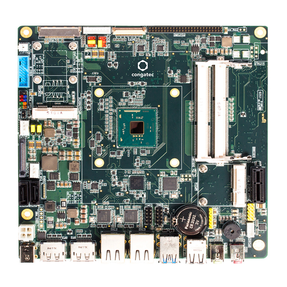
Summary of Contents for Congatec conga-IA4
- Page 1 Thin Mini-ITX SBC Detailed Description Of The congatec Thin Mini-ITX Based On 4th Generation Intel Celeron/Pentium SoCs User's Guide Revision 1.2...
- Page 2 Updated sections 2.5 "Power Consumption" and 2.6 "Supply Voltage Battery Power" • Updated the block diagram • Updated section 8 "BIOS Setup Description" • Added sub-sections to section 9 "Additional BIOS Features" and updated section 9.4 "Supported Flash Devices" Copyright © 2016 congatec AG IA40m12.indd 2/97...
- Page 3 In no event shall congatec AG be liable for any incidental, consequential, special, or exemplary damages, whether based on tort, contract or otherwise, arising out of or in connection with this user’s guide or any other information...
- Page 4 Copyright © 2016, congatec AG. All rights reserved. All text, pictures and graphics are protected by copyrights. No copying is permitted without written permission from congatec AG. congatec AG has made every attempt to ensure that the information in this document is accurate, yet the information contained within is supplied “as-is”.
- Page 5 (c) arising from course of performance, course of dealing, or usage of trade. congatec AG shall in no event be liable to the end user for collateral or consequential damages of any kind. congatec shall not otherwise be liable for loss, damage or expense directly or indirectly arising from the use of the product or from any other cause.
- Page 6 Technical Support congatec AG technicians and engineers are committed to providing the best possible technical support for our customers so that our products can be easily used and implemented. We request that you first visit our website at www.congatec.com for the latest documentation, utilities and drivers, which have been made available to assist you.
-
Page 7: Table Of Contents
Case Open Intrusion Connector ..........50 Audio Interfaces ............... 27 Trusted Platform Module – TPM (Optional) ......50 5.3.1 Rear Audio Connectors ............27 congatec Board Controller (cBC) ..........50 5.3.2 Internal Audio Connectors ............28 6.4.1 Fan Control ................50 5.3.2.1... - Page 8 PPM Configuration Submenu ..........72 6.5.5 OEM DXE Driver ..............52 8.4.16 Thermal Configuration ............. 72 congatec Battery Management Interface ........ 52 8.4.17 SATA Submenu ................ 73 API Support (CGOS) ..............53 8.4.17.1 Software Feature Mask Configuration Submenu ..... 73 Thermal/Voltage Monitoring............
- Page 9 Navigating the BIOS Setup Menu ........... 95 BIOS Versions................95 Updating the BIOS ..............95 Supported Flash Devices ............96 Industry Specifications ............. 97 Copyright © 2016 congatec AG IA40m12.indd 9/97...
- Page 10 List of Tables Table 1 conga-IA4 Variants ..............12 Table 37 Connector X30 Pinout Description .......... 43 Table 2 Cooling/IO Shield ..............12 Table 38 Connector X51 Pinout Description .......... 44 Table 3 Memory Modules ..............12 Table 39 x1 PCIe Slot (Connector X9) Pinout Description ...... 44 Table 4 Cables ..................
-
Page 11: Introduction
With smaller board size and lower height keep-out zones, the conga-IA4 SBC provides manufacturers and enthusiasts with the opportunity to design compact systems for space restricted areas. With appropriate I/O shield, the same conga-IA4 SBC can be used in either a Thin Mini-ITX or a Mini-ITX design. -
Page 12: Options Information
Retention frame for conga-IA4 standard cooling conga-IA4 IO Shield Standard Size 052651 IO shield for conga-IA4 with standard Mini-ITX chassis (40 mm height) conga-IA4 IO Shield Thin Size 052651 IO shield for conga-IA4 with Thin Mini-ITX chassis (25 mm height) -
Page 13: Table 4 Cables
Part No. Description conga-Thin MITX/LVDS Adapter 052233 LVDS pin header evaluation adapter for congatec Thin Mini-ITX boards conga-Thin MITX/Debug Card 047858 Evaluation debug card with post code display, buttons, status LED's; also for external BIOS update and other useful IO's Copyright ©... -
Page 14: Specification
Celeron ® N3160, N3060, N3010 Memory Two memory sockets (located on the top side of the conga-IA4). Supports: SO-DIMM non-ECC DDR3L modules Data rates up to 1600 MT/s Maximum 8 GB capacity Multi-stage watchdog, manufacturing and board information, board statistics, I2C bus, Power loss control... -
Page 15: Supported Operating Systems
Also make sure the memory modules support the data transfer rate of the particular variant. In addition, when using one memory socket, insert the memory module only in the first memory slot on the conga-IA4 (top side). If the first memory slot is empty, the SoC on the conga-IA4 ignores the second memory socket (bottom side). -
Page 16: Supply Voltage Power
Power Consumption The power consumption values were measured with the following setup: • conga-IA4 COM • modified congatec carrier board • conga-IA4 cooling solution • 12 V input voltage for S0 states and 5 V for S3 and S5 states •... -
Page 17: Supply Voltage Battery Power
Table 8 Power Consumption Values The tables below provide additional information about the power consumption data for each of the conga-IA4 variants offered. The values are recorded at various operating mode. Part Memory BIOS Current (A) Size Rev. Rev. (64-bit) -
Page 18: Environmental Specifications
Operation: 0° to 60°C Storage: -20° to +80°C Humidity Operation: 10% to 90% Storage: 5% to 95% Note The above operating temperatures must be strictly adhered to at all times. Humidity specifications are for non-condensing conditions. Copyright © 2016 congatec AG IA40m12.indd 18/97... -
Page 19: Block Diagram
ALC888S Internal speaker Reverse Polarity Protection Audio HeadPh External I/O Internal I/O optional Power IN Audio MIC The mSATA/mPCIe connector supports both mPCIe and mSATA devices. The devices are detected automatically. Optional feature. Copyright © 2016 congatec AG IA40m12.indd 19/97... -
Page 20: Cooling Solution
Nonetheless, all electronics contain semiconductor devices which have operating temperature ranges that should be adhered to. This means that for reliable operation, the thermal design of the conga-IA4 must be carefully considered. For this reason, it is imperative to provide sufficient air flow to each of the components, to ensure the specified operating temperature of the conga-IA4 is maintained. -
Page 21: Cooling Installation
The congatec cooling solutions are designed for commercial temperature range only (0° to 60°C). Therefore, do not use the congatec CSP in temperatures above 60°C or below 0°C. If an end user’s system operates above 60°C or below 0°C, or is assembled with a non-congatec cooling solution, then the end user must use or design an optimized thermal solution that meets the needs of their application. -
Page 22: Csp Dimensions
CSP Dimensions Note All measurements are in millimeters. Torque specification for cooling solution screws is 0.3 Nm. Mechanical system assembly mounting shall follow the valid DIN/IS0 specifications. Copyright © 2016 congatec AG IA40m12.indd 22/97... -
Page 23: Connector Description
Connector Description Power Supply You can power the conga-IA4 SBC with a 12V-24V laptop type DC power supply (on connector X43) or a 4 pin internal power supply (on connector X44). Additionally, the SBC offers an optional SBM power connector (only BOM option). When this connector (X50) is populated, you can power the SBC with it. -
Page 24: Power Supply (Internal Connector)
Caution The absolute maximum rating of the input voltage is 36 volts. Do not exceed this rating or expose the conga-IA4 to the absolute maximum voltage for a prolonged time. Doing so may damage the system or affect system reliability. -
Page 25: Optional Sbm3 Signal Connector
Caution The absolute maximum rating of the input voltage is 36 volts. Do not exceed this rating or expose the conga-IA4 to the absolute maximum voltage for a prolonged time. Doing so may damage the system or affect system reliability. -
Page 26: Pwr_Ok Signal
Power Status LEDs The conga-IA4 provides two LED signals (FP_LED+ and P_LED-) on pins 2 and 4 of the front panel connector X38. The signals indicate the different power states of the conga-IA4. Possible states and corresponding activity of the LEDs are shown below:... -
Page 27: Cmos Battery/Rtc
Audio Interfaces The conga-IA4 provides audio connectors both internally and on the rear side. The internal audio connectors are stereo speaker, digital microphone/SPDIF and front Panel HD audio. The rear audio connectors are Line-OUT and Mic-IN. -
Page 28: Internal Audio Connectors
X62: 6 pin, single audio jack - pink color 5.3.2 Internal Audio Connectors The conga-IA4 provides the stereo speaker, digital microphone/SPDIF and front panel HD audio connectors internally. 5.3.2.1 Stereo Speaker Header The first analog line input channels (left and right) of the Realtek ALC888S HDA audio codec are routed via a TPA2012D2 amplifier to internal stereo speaker - connector X19. -
Page 29: Digital Microphone/Spdif
Digital MIC/SPDIF - Connector X17 +3.3V 3.3V supply DMIC_DATA Serial data from digital MIC Ground SPDIFO2 Secondary S/PDIF output Pin 1 No pin 5V supply No Pin Connector Type X17: 2.54mm, 1x6 pin header Copyright © 2016 congatec AG IA40m12.indd 29/97... -
Page 30: Front Panel Hd Audio
Communication Bus The conga-IA4 supports both SMBus and I2C compliant devices. 5.4.1 SMBus The SMBus signals are available in different locations on the conga-IA4, including the feature connector (X34) described in section 6.13 of this document. 5.4.2 I²C Bus The congatec Board controller provides I²C signals. These signals are available in different locations on the conga-IA4, including the feature connector (X34) described in section 6.13 of this document. -
Page 31: Spi Bus
Serial Ports (COM) The Super I/O controller on the conga-IA4 provides two fully featured RS-232 compliant UART interfaces (COM 0 and 1). The COM 1 interface can be optionally used as ccTALK compliant interface. The COM ports can drive up to 115 kbit/s at a maximum cable length of 15 m. -
Page 32: Cpu/System Fan Connector & Power Configuration
CPU/System Fan Connector & Power Configuration The conga-IA4 supports the connection of 5V or 12V cooling fans. The signals of the CPU and system fans are routed to 4-pin connectors X35 and X37 respectively. Use jumper X33 to select the CPU fan voltage and jumper X36 to select the system fan voltage. -
Page 33: Universal Serial Bus (Usb)
Universal Serial Bus (USB) The conga-IA4 provides 6 USB ports - 4 USB ports on the rear side and 2 USB ports internally. The USB routing diagram is shown below: Intel Braswell SoC USB HUB To mPCIe Connector To mPCIe/mSATA Connector 2x USB 2.0 Rear Ports... -
Page 34: Rear Usb Connectors
5.6.1 Rear USB Connectors The conga-IA4 offers four USB ports on the rear side - two USB 2.0 ports on connector X14 and two USB 3.0 ports on connector X15. The pinouts are described below: Table 25 USB 2.0 (Connector X14) Pinout Descriptions... -
Page 35: Internal Usb Connector
5.6.2 Internal USB Connector The conga-IA4 offers two USB 3.0 ports on connector X60 (internal header). The ports are backward compatible to USB 2.0 devices. Table 27 USB 3.0 Header (Connectors 60) Pinout Description Port 3 Port 2 Pin Signal... -
Page 36: Ethernet 10/100/1000
Ethernet 10/100/1000 The conga-IA4 provides two Gigabit Ethernet ports (connectors X57 and X58) on the rear side. The two Gigabit Ethernet interfaces are supported via the Intel Gigabit Ethernet controller i211. Table 28 Connectors X57/X58 Pinout Description Description 10base-T 100Base-T... -
Page 37: Sata Interfaces
Standard SATA Ports The conga-IA4 provides two SATA ports. The SATA ports are routed to connectors CN1/CN2 and support data rates up to 6 Gb/s. The SATA LED on the front panel connector (X38) is lit when there is activity on any of the SATA interfaces. -
Page 38: Mini Sata
Mini SATA The mini SATA connector X6 on the conga-IA4 is used to connect mSATA devices. This connector shares the SoC's SATA1 signals with SATA connector CN2. Connector CN2 will not function whenever an mSATA card is inserted into the mSATA connector. Therefore, if you plan to use connector CN2, do not insert an mSATA device into connector X6. - Page 39 X6: 0.8mm pitch, 52 pin mini PCI socket Note * For card presence detection, pin 21 of the mSATA card must be terminated to ground. For card type recognition, pin 43 of the mSATA card must be unconnected. Copyright © 2016 congatec AG IA40m12.indd 39/97...
-
Page 40: Display Interfaces
The conga-IA4 supports three simultaneous displays - two DP++ and an LVDS interface. 5.9.1 Display Port Interface DP++ The conga-IA4 SBC has two DP++ connectors (X26 and X27) located at the rear I/O panel. The DP++ connectors support DP, HDMI and DVI displays. Table 33 Connectors X26 Pinout Description. -
Page 41: Table 34 Connector X32 Pinout Description
X32: 0.5mm, 40 pin ACES connector. Possible Mating Connector: ACES 88441-40 and ACES 50204-40. Note congatec offers cables and adapter for the LVDS interface (see section 1.2.2 “Optional Accessories”). For more information, contact congatec technical solution department. Copyright © 2016 congatec AG IA40m12.indd... -
Page 42: Backlight Power Connector
5.9.2.1 Backlight Power Connector The conga-IA4 provides backlight power on connector X31. The power budget of BKLT_PWR (pins 3 and 4) is limited to 1.5 amps. Table 35 Connector X31 Pinout Description Backlight Power - Connector X31 Signal Name Description... -
Page 43: Backlight/Panel Power Selection
Backlight/Panel Power Selection The conga-IA4 supports different voltages for the panel and backlight connectors. With jumper X29, you can set the panel voltage to 3,3V, 5V or 12V. With jumper X30, you can set the backlight voltage to 5V or 12V. -
Page 44: Monitor Off Connector
X51: 2.54mm, 2 pin Molex connector. 5.10 PCI Express The conga-IA4 provides 3 PCIe interfaces - a x1 PCIe slot on connector X9, a half-size mini PCIe (mPCIe) slot on connector X10 and a full size mini PCIe/mini SATA slot on connector X6. 5.10.1 x1 PCIe Slot The conga-IA4 offers one PCIe x1 slot on connector X9. -
Page 45: Mini Pcie (Half Size)
Mini PCIe (Half Size) The conga-IA4 is equipped with a PCIe Mini Card socket (connector X10). PCI Express Mini Card is a unique small size form factor optimized for mobile computing platforms. The small footprint connector makes it possible to mount upgradable, standardized PCI Express Mini Card device to the SBC without additional expenditure of a redesign. - Page 46 Pull down resistor (1M) N.C. W_DISABLE# PERST# PERn0 +3.3Vaux PERp0 +1.5V SMB_CLK PETn0 SMB_DATA PETp0 USB_D- USB_D+ +3.3Vaux +3.3Vaux mSATA_mPCIe_detect CL_CLK CL_DATA +1.5V CL_RST# N.C. +3.3Vaux Connector Type X10: PCIe mini card socket Copyright © 2016 congatec AG IA40m12.indd 46/97...
-
Page 47: Mini Pcie (Full Size)
5.10.3 Mini PCIe (Full Size) The conga-IA4 offers an mPCIe slot on connector X6. This connector shares the SoC's PCIe 0 signals with connector X9 (x1 PCIe slot), via a multiplexer. The mPCIe slot supports both mPCIe and mSATA devices. When an mPCIe or mSATA device is attached to the mPCIe/mSATA slot (connector X6), the SoC automatically detects the type of device that is attached (via pin 43 - the signal detect pin) See section 5.10.2 "Mini PCIe (Half Size)"... -
Page 48: Pci Express Routing
X6 (mPCIe/mSATA). If you intend to use connector X9 , do not insert any mini PCIe device into connector X6. Mini PCIe Slot PCIe Lane 1 USB Signals Copyright © 2016 congatec AG IA40m12.indd 48/97... -
Page 49: Additional Features
Front Panel Connector The conga-IA4 SBC supports front panel features such as power button, status LEDs and reset button via connector X38 - a 10-pin internal header. This connector offers one power supply pin (3.3V). The signals FP_LED+ and FP_LED- communicates the system states to two LEDs connected to this header. -
Page 50: Case Open Intrusion Connector
Trusted Platform Module – TPM (Optional) The conga-IA4 SBC can optionally be equipped with a TPM 1.2 compliant security chip. The TPM security chip is connected to the LPC bus provided by the integrated Intel Chipset. The basic TPM chip initialization is performed by the SBC’s UEFI Boot firmware. -
Page 51: Power Loss Control
It also keeps track of dynamically changing data like runtime meter and boot counter. 6.4.4 GPIOs The conga-IA4 SBC provides eight General Purpose Inputs via the congatec board controller and eight General Purpose Outputs via the onboard Super I/O. The GPIO signals are routed to the feature connector X34. OEM BIOS Customization The conga-IA4 is equipped with congatec Embedded BIOS, which is based on American Megatrends Inc. -
Page 52: Oem Boot Logo
OEM POST Logo This feature allows system designers to replace the congatec POST logo displayed in the upper left corner of the screen during BIOS POST with their own BIOS POST logo. Use the congatec system utility CGUTIL 1.5.4 or later to replace/add the OEM POST logo. -
Page 53: Api Support (Cgos)
The architecture of the CGOS API driver provides the ability to write application software that runs unmodified on all congatec CPU modules. All the hardware related code is contained within the congatec embedded BIOS on the module. See section 1.1 of the CGOS API software developers guide, which is available on the congatec website . -
Page 54: Beeper
The conga-IA4 supports LAN, USB, PCIe and PWRBTN driven wake up events. 6.11 Feature Connector The conga-IA4 provides an internal 50 pol. 2mm pin header as feature connector. The pinout is described below: Table 43 Feature Connector X34 Pinout Description... - Page 55 Signal GPI2 GPI3 GPI4 GPI5 GPI6 GPI7 PM_SLP_S3# PM_SLP_S5# PM_SLP_S4# LID_BTN# SLP_BTN# PM_THRM# WDOUT WDTRIG I2C_DAT PWR_OK SPI_CS# I2C_CLK SPI_SO BIOS_DISABLE# SPI_CLK SPI_SI +V5A Connector Type X34: 2mm, 2 x 25 pin header. Copyright © 2016 congatec AG IA40m12.indd 55/97...
-
Page 56: Conga-Ia4 Mechanical Drawing
Mechanical Drawing LVDS BACKLIGHT FEATURE CONNECTIOR TPM PP FULL-MINI CARD HALF-MINI CARD Mini PCIe / mSATA DISPLAY DISPLAY PORT ++ PORT ++ 6.35 44.47 63.76 114.76 132.35 156.55 163.83 Copyright © 2016 congatec AG IA40m12.indd 56/97... -
Page 57: Bios Setup Description
BIOS setup program. Setup Menu and Navigation The congatec BIOS setup screen is composed of the menu bar, left frame and right frame. The menu bar is shown below: Main... -
Page 58: Main Setup Screen
Serial Number No option Displays the serial number of the board. BC Firmware Revision No option Displays the firmware revision of the congatec board controller. MAC Address (1 Ethernet) No option Displays the MAC address of the onboard Ethernet controller. -
Page 59: Advanced Setup
I211 Gigabit Network (Ethernet 2) Driver Health Trusted Computing RTC Wake Reserve Legacy Interrupt ACPI Super IO Serial Port Console Redirection PPM Configuration Thermal Configuration SATA LPSS & SCC Configuration PCI & PCI Express Copyright © 2016 congatec AG IA40m12.indd 59/97... -
Page 60: Watchdog Submenu
Delay Disabled The runtime watchdog is delayed for the selected time. Note: Use this feature to ensure that the operating system has enough time to load. 10sec 30sec 1min 2min 5min 10min 30min Copyright © 2016 congatec AG IA40m12.indd 60/97... - Page 61 Note In ACPI mode, the "Watchdog ACPI Event" handler cannot restart or shutdown the OS directly. For this reason, the congatec BIOS will • For shutdown: execute an over-temperature notification. This causes the operating system to shut down in an orderly fashion •...
-
Page 62: Hardware Health Monitoring Submenu
Select minimum/start fan speed to be set when the start temperature of the control slope is reached. Setting 70%, 100% CPU Fan Speed Mode Smart Mode Configures the CPU Fan Mode PWM Mode Copyright © 2016 congatec AG IA40m12.indd 62/97... -
Page 63: Graphics Submenu
LVDS panel. Auto detection is performed by reading an EDID™ data set via the video I²C bus. VGA 640x480 1x18 (013h) The number in brackets specifies the congatec internal number of the respective panel data set. WVGA 800x480 1x18 (01Fh) Note: Customized EDID™... - Page 64 Auto Selection Digital Display Interface 1 Select the output type of the DDI 1. Disabled DisplayPort HDMI/DVI Digital Display Interface 2 Auto Selection Select the output type of the DDI 2. Disabled DisplayPort HDMI/DVI Copyright © 2016 congatec AG IA40m12.indd 64/97...
-
Page 65: Intel ® I211 Gigabit Network Connection (Ethernet 1) Submenu
Displays the MAC Address. 8.4.5.1 NIC Configuration Submenu Feature Options Description Auto Negotiated Link Speed Set the port speed for the selected boot protocol. 10 Mbps Half 10 Mbps Full 100 Mbps Half 100 Mbps Full Copyright © 2016 congatec AG IA40m12.indd 65/97... -
Page 66: Driver Health Submenu
Specify the wake up hour. For example: Enter “3” for 3am and “15” for 3pm. Wake up minute 0 - 59 Specify the wake up minute. Wake up second 0 - 59 Specify the wake up second. Copyright © 2016 congatec AG IA40m12.indd 66/97... -
Page 67: Reserve Legacy Interrupt Submenu
Super IO Submenu Feature Options Description Super IO Chip No option Displays super IO chip. ►Serial Port 1 Configuration Submenu Serial port 1 submenu. ►Serial Port 2 Configuration Submenu Serial port 2 submenu. Copyright © 2016 congatec AG IA40m12.indd 67/97... -
Page 68: Serial Port 1 Configuration Submenu
COM0 Console Redirection Disabled Enable or disable serial port 0 console redirection. Enabled ►Console Redirection Settings Submenu Opens 'Console Redirection Settings' submenu. COM1 Console Redirection Disabled Enable or disable serial port 0 console redirection. Enabled Copyright © 2016 congatec AG IA40m12.indd 68/97... -
Page 69: Console Redirection Settings Submenu
Note: This feature is helpful to capture and record terminal data. Resolution 100x31 Disabled Enable or disable extended terminal resolution. Enabled Legacy OS Redirection 80x24 Select the number of rows and columns for the legacy operating system redirection. Resolution 80x25 Copyright © 2016 congatec AG IA40m12.indd 69/97... -
Page 70: Legacy Console Redirection Settings
Set the baud rate. 19200 38400 57600 115200 Flow Control None Hardware RTS/CTS Sotware Xon/Xoff Data Bits Set the number of data bits. Parity None Set the parity. Stop Bits Set the number of stop bits. Copyright © 2016 congatec AG IA40m12.indd 70/97... -
Page 71: Cpu Configuration Submenu
Displays the CPU signature number. Microcode Patch No option Displays the CPU microcode patch number. Max CPU Speed No option Displays the maximal CPU clock frequency. Min CPU Speed No option Displays the minimal CPU clock frequency. Copyright © 2016 congatec AG IA40m12.indd 71/97... -
Page 72: Ppm Configuration Submenu
Set the temperature at which the fan is activated at full speed. Full Speed Fan Trip Point 0 - 90 Half Speed Fan Trip Point Default: 60 Set the temperature at which the fan is activated at half speed. 0 - 90 Copyright © 2016 congatec AG IA40m12.indd 72/97... -
Page 73: Sata Submenu
If enabled, indicates that the HDD password unlock in the operating system is enabled. Disabled Enabled LED Locate If enabled, indicates that the LED/SGPIO hardware is attached and ping to locate feature is enabled on Disabled the OS. Copyright © 2016 congatec AG IA40m12.indd 73/97... -
Page 74: Lpss & Scc Configuration Submenu
LPSS I2C #4 ACPI Mode Enable or disable LPSS I2C #4 support. PCI Mode Disabled 8.4.19 PCI & PCI Express Feature Options Description PCI Bus Driver Version No option Displays PCI bus driver version. Copyright © 2016 congatec AG IA40m12.indd 74/97... -
Page 75: Uefi Network Stack
If this feature is disabled, IPV6 PXE boot option will not be created. Disabled PXE boot wait time 0 - 5 Set wait time to press ESC key to abort the PXE boot. Copyright © 2016 congatec AG IA40m12.indd 75/97... -
Page 76: Csm & Option Rom Control Submenu
Select the execution of UEFI and legacy option ROMs for any PCI device other than network, video and storage. Legacy only Do not launch 8.4.22 Info Report Configuration Feature Options Description POST Report Disabled Enable or disable POST report support. Enabled Copyright © 2016 congatec AG IA40m12.indd 76/97... -
Page 77: Nvme Submenu
Hand-off Enabled This is a workaround for operating systems without xHCI hand-off support. Disabled Note: If this feature is enabled, the xHCI ownership change should be claimed by xHCI operating system driver. Copyright © 2016 congatec AG IA40m12.indd 77/97... -
Page 78: Security Configuration
SparkFun device is 0xE2. However, any even device address (bit 0 = 0) can be specified. BC Diagnostic Console Disable Select the interface to be used for the BC Diagnostic Console output or disable the BC Diagnostic Interface BC AUX Port Console output. Copyright © 2016 congatec AG IA40m12.indd 78/97... -
Page 79: Platform Trust Technology
Enable or disable Host ME Region Flash Protection Overwrite (HMRFPO). Disable TXE Firmware Update Enabled Enable or disable firmware update. Disabled TXE EOP Message Enabled Enable or disable TXE End of Post (EOP) Message. Disabled Copyright © 2016 congatec AG IA40m12.indd 79/97... -
Page 80: Intel ® Rmt Configuration Submenu
Processor (Integrated Components) Submenu Feature Options Description ►Intel IGD Configuration Submenu ►Graphics Power Management Control Submenu ►Memory Configuration Options Submenu Total Memory No option Displays the total amount of memory detected by the system Copyright © 2016 congatec AG IA40m12.indd 80/97... -
Page 81: Intel ® Igd Configuration Submenu
320M 352M 384M 416M 448M 480M 512M DVMT Total Gfx Mem 128MB Select DVMT 5.0 total graphic memory size used by the IGD. 256MB Aperture Size 128MB Select the aperture size. 256MB 512MB Copyright © 2016 congatec AG IA40m12.indd 81/97... -
Page 82: Graphics Power Management Control Submenu
BSW I2C PMIC Config 8.5.1.2 Graphics Power Management Control Submenu Feature Options Description RC6 (Render Standby) Enabled Enable or disable render standby support. Disabled Power Meter Lock Enabled Enable or disable power meter lock. Disabled Copyright © 2016 congatec AG IA40m12.indd 82/97... -
Page 83: Memory Configuration Options Submenu
Set channel selection bit 3:0 (hexadecimal). 0 - F Channel Selection 4 Default: 1 BMISC Channel select 4 for channel hashing (hexadecimal). 0 - F Bank Address Hashing Disabled Enable or disable bank address hashing. Enabled Copyright © 2016 congatec AG IA40m12.indd 83/97... -
Page 84: Platform Controller Hub (Pch) Submenu
Select IRQ Serial Mode. Continuous Isolate SMBus Segments Never Isolate the off-module/external SMBus segment from the on-module SMBus segment. During POST This feature is a workaround for non spec conform external SMBus devices. Always Copyright © 2016 congatec AG IA40m12.indd 84/97... -
Page 85: Security Configuration Submenu
Enabled Enable or disable HDMI port B audio. Disabled HDMI Port C Enabled Enable or disable HDMI port C audio. Disabled HDMI Port D Enabled Enable or disable HDMI port D audio. Disabled Copyright © 2016 congatec AG IA40m12.indd 85/97... -
Page 86: Usb Configuration Submenu
► PCIE Express Root Port 3 Submenu ► PCIE Express Root Port 4 Submenu ► PCIE Express S0ix Settings Submenu Native PCI Express Support Disabled Enable or disable native operating system PCIe support Enabled Copyright © 2016 congatec AG IA40m12.indd 86/97... - Page 87 L1 Substates Disabled Select PCIe L1 substates setting. L1.1 L1.2 L1.1 & L1.2 Non-Common Clock With SSC Enabled Enable this feature if the root port is operating at non-common clock. Disabled Enabled Mode Copyright © 2016 congatec AG IA40m12.indd 87/97...
-
Page 88: Security Setup
Select the Security tab from the setup menu to enter the Security setup screen. 8.6.1 Security Settings Feature Options Description BIOS Password No options Set BIOS password. BIOS Lock Enabled Enable or disable the BIOS lock feature Disabled Copyright © 2016 congatec AG IA40m12.indd 88/97... -
Page 89: Secure Boot Menu
Force system to user mode and install all factory default keys. ►Platform Key(PK) ►Key Exchange Keys ►Authorized Signatures ►Forbidden Signatures ►Authorized TimeStamps Boot Setup Select the Boot tab from the setup menu to enter the Boot setup screen. Copyright © 2016 congatec AG IA40m12.indd 89/97... -
Page 90: Boot Settings Configuration
Select the system state after a shutdown if a battery system is connected. S5/Soft Off Fast Boot Disabled Enable this feature to boot with a minimum set of devices. Note: This feature has no effect on BBS / legacy boot options. Enabled Copyright © 2016 congatec AG IA40m12.indd 90/97... - Page 91 Firmware-based Bootloader Other Device 3rd Boot Device Disabled SATA 0 Drive SATA 1 Drive NVMe Storage USB Harddisk USB CDROM Other USB Device Onboard eMMC Storage Onboard LAN External LAN Firmware-based Bootloader Other Device Copyright © 2016 congatec AG IA40m12.indd 91/97...
- Page 92 Firmware-based Bootloader Other Device 6th Boot Device Disabled SATA 0 Drive SATA 1 Drive NVMe Storage USB Harddisk USB CDROM Other USB Device Onboard eMMC Storage Onboard LAN External LAN Firmware-based Bootloader Other Device Copyright © 2016 congatec AG IA40m12.indd 92/97...
- Page 93 Note The term ‘AC power loss’ stands for the state when the module looses the standby voltage on the 5V_SB pins. On congatec modules, the standby voltage is continuously monitored after the system is turned off. If within 30 seconds the standby voltage is no longer detected, then this is considered an AC power loss condition.
-
Page 94: Save & Exit Menu
Only visible and active if Boot Priority Selection setup node is set to “Device Based”. Generate Menu Layout File Menu layout file will be generated and stored on the first writable file system found. Copyright © 2016 congatec AG IA40m12.indd 94/97... -
Page 95: Additional Bios Features
OEMs often use BIOS updates to correct platform issues discovered after the board has been shipped or when new features are added to the BIOS. The conga-IA4 uses a congatec/AMI AptioEFI firmware, which is stored in an onboard flash ROM chip and can be updated using the congatec System Utility. -
Page 96: Supported Flash Devices
Note The flash device listed above has been tested and can be used on the congatec debug adapter (PN:047858) listed in table 5 "Adapters". For more information about external BIOS support, refer to the Application Note AN7_External_BIOS_Update.pdf on the congatec website at http://www.congatec.com. -
Page 97: Industry Specifications
Industry Specifications The list below provides links to industry specifications that apply to congatec AG modules. Specification Link Low Pin Count Interface Specification, Revision 1.0 (LPC) http://developer.intel.com/design/chipsets/industry/lpc.htm Universal Serial Bus (USB) Specification, Revision 2.0 http://www.usb.org/home PCI Specification, Revision 2.3 http://www.pcisig.com/specifications Serial ATA Specification, Revision 3.0...
Need help?
Do you have a question about the conga-IA4 and is the answer not in the manual?
Questions and answers