Sign In
Upload
Download
Table of Contents
Contents
Add to my manuals
Delete from my manuals
Share
URL of this page:
HTML Link:
Bookmark this page
Add
Manual will be automatically added to "My Manuals"
Print this page
×
Bookmark added
×
Added to my manuals
Manuals
Brands
FNM Manuals
Engine
HPEP 225
Installation manual
FNM HPEP 225 Installation Manual
Hide thumbs
1
Table Of Contents
2
3
4
5
6
7
8
9
10
11
12
13
14
15
16
17
18
19
20
21
22
23
24
25
26
27
28
29
30
31
32
33
34
35
36
37
38
39
40
41
42
43
44
45
46
47
48
49
50
51
52
53
54
55
56
57
58
59
60
61
62
63
64
65
66
67
68
69
70
71
72
73
74
75
76
77
78
79
80
81
82
83
84
85
86
87
88
89
90
91
92
93
94
95
96
97
98
99
100
101
102
103
104
105
106
107
108
109
110
111
112
113
114
115
116
117
118
119
120
121
122
123
page
of
123
Go
/
123
Contents
Table of Contents
Troubleshooting
Bookmarks
Table of Contents
Table of Contents
General Information
Operation/Duty Cycle Rating Notice
Bravo Three Notice: Increased Trim-In Range Capability
Multiple Sterndrive Steering Tie Bar
Propeller Rotation on Dual Installations
Quicksilver Products
Torque Specifications
Serial Number Decal Placement
Corrosion Protection
Antifouling Paint
Installation Requirements
Transom Thickness and Surface
Engine Bed
Engine Compartment
Engine Compartment Ventilation
Exhaust System
Fuel Delivery System
Battery
Battery Cables
Instrumentation
Power Trim Control
Power Trim Pump Location
Propeller Selection
Steering Helm and Cable
Transom Cutout
Cutting Transom
Installing Gimbal Housing
Installing Inner Transom Plate
Installing Power Trim Pump
Installing Steering System
Connecting Speedometer Pickup
Connecting Gear Lube Monitor Hose and Installing Water Inlet Fitting
Checking Transom Thickness
Installing Transom Assembly
Description of the Engine
Engine Installation
Engine Identification
Transom Preparation
Engine Connections
Electrical Connections
Shift Cable Installation
Troubleshooting Shift Problems
Throttle Cable Installation and Adjustment
Sterndrive Installation
Battery Connection
Predelivery Preparation
Power Trim Pump
Trim Position Sender Adjustment
Power Steering Fluid
Test Running Engine
Power Trim System
Wiring Diagrams
Advertisement
Quick Links
1
General Information
2
Fuel Delivery System
3
Electrical Connections
4
Wiring Diagrams
Download this manual
1
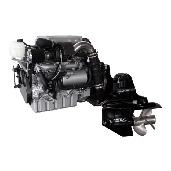
INSTALLATION MANUAL
HPEP 225 - HPEP 250
DIESEL ENGINE & BRAVO STERN DRIVES
First Release
May 2006
Table of
Contents
Previous
Page
Next
Page
1
2
3
4
5
Advertisement
Table of Contents
Need help?
Do you have a question about the HPEP 225 and is the answer not in the manual?
Ask a question
Questions and answers
Related Manuals for FNM HPEP 225
Engine FNM HPE 300 Owner's Manual
Marine diesel engine (78 pages)
Engine FNM HPEP 250 Installation Manual
(123 pages)
Engine FNM HPE Series Owner's Manual
(149 pages)
Engine FNM HPE Series Installation Manual
Marine diesel engines (57 pages)
Engine FNM 13HPE 40 Owner's Manual
Marine diesel engines (134 pages)
Engine FNM 13HPE 80 Owner's Manual
Marine diesel engines (134 pages)
Engine FNM 13HPE 80JD Owner's Manual
Marine diesel engines (134 pages)
Engine FNM 13HPE 80SD Owner's Manual
Marine diesel engines (134 pages)
Engine FNM 13HPE 110 Owner's Manual
Marine diesel engines (134 pages)
Engine FNM 13HPE 110JD Owner's Manual
Marine diesel engines (134 pages)
This manual is also suitable for:
Hpep 250
Table of Contents
Save PDF
Print
Rename the bookmark
Delete bookmark?
Delete from my manuals?
Login
Sign In
OR
Sign in with Facebook
Sign in with Google
Upload manual
Upload from disk
Upload from URL


Need help?
Do you have a question about the HPEP 225 and is the answer not in the manual?
Questions and answers