
Related Manuals for FNM HPE Series


Summary of Contents for FNM HPE Series
- Page 1 Owner’s Manual HPE 40S/80/80SD/110/110JD HPE/P 40/150/150JD/170/170JD/190/190JD Marine Diesel Engines HPE/P 100/225/225JD/250/250JD/250H HPE Series HPE/P 300 HPEL 45/80/65/90...
-
Page 5: Table Of Contents
About this manual Guidance on identification of important information ® Notes on FNM engines servicing Identification of your engine General safety regulations Main components of FNM ® engine, HPE Series Engine delivery ® Using the FNM engine, HPE series Analog Instrument Panel... - Page 6 Engine treatment and maintenance products Periods of engine inactivity Other useful information for maintenance Specifications of your engine Maintenance booklet Engine Identification Data | Dati identificativi del motore Ordinary and Extraordinary Maintenance Register | Registro della manutenzione periodica programmata e straordinaria ® HPE Series...
-
Page 7: General Information
1 General information ® HPE Series... - Page 8 Dear customer Fratelli Negri Motori (hereinafter FNM ) is pleased to thank you for choosing an engine of HPE range. ® engines are designed and developed according to the demand and the needs of customers and builders of pleasure and work boats.
-
Page 9: About This Manual
1.1 About this manual This manual is integral part of the engine and is written by the manufacturer to inform the end user of the procedures necessary for the proper use and maintenance of marine diesel engine FNM, HPE Series. -
Page 10: Guidance On Identification Of Important Information
1.2 Guidance on identification of important information In the manual you will find a color guide that indicates the degree of importance of information for use ® or maintenance of your FNM engine. There are three levels of importance: Danger icon: dangerous situations that may compromise the safety of persons and engine functionality. -
Page 11: Notes On Fnm ® Engines Servicing
FNM service. ® If the installer does not transmit the installation form to FNM this may invalidate the warranty. ® To get help on your engine and for warranty information, please feel free to contact FNM service.fnm@cmdengine.com. ® HPE Series... - Page 12 The use of non-original spare parts may cause the warranty to expire and it also exempts the ® company CMD S.p.A (owner of the FNM brand name and logo) from any responsibility. 1.3.2 Responsibility The ...
-
Page 13: Identification Of Your Engine
1.4 Identification of your engine The ID label is applied on your engine and on the control unit (or ECU box) in the position indicated in ® the table below (see also paragraph Main components of FNM engine, HPE Series on page 15): Engine... - Page 14 The engine serial number is also printed on the engine block. The position is indicated in the table ® below (see also paragraph Main components of FNM engine, HPE Series on page 15): Engine Engine serial number position HPE 40S/80/80SD/110/110JD HPE/P 40/150/150JD/170/170JD/190/190JD On the crankcase, right side, bell housing connection.
-
Page 15: General Safety Regulations
During the installation the installer shall follow the manufacturer’s instructions. Do not make changes to the engine components for any reason! ® HPE Series... - Page 16 Avoid contact of hands with the rotor. Do not touch the turbocharger and the turbine cover with hands immediately after using the engine, risk of burns. Let engine cool before interacting with the hot parts. ® HPE Series...
- Page 17 1.5.1 Residual risks Potential/additional risks to persons: Risk of injury: do not put hands in any moving parts (pulleys, flywheel, belts, etc.). Risk of burns: attention to hot surfaces (exhaust manifold, turbocharger, raiser, etc.) ® HPE Series...
- Page 18 Risk of shock: use safety shoes when lifting the engine and/or working in the engine compartment. FNM ® is not responsible for damage caused by misuse of the engine and the failure to follow procedures issued, as well as for damage caused by unauthorized personnel.
-
Page 19: Main Components Of Fnm ® Engine, Hpe Series
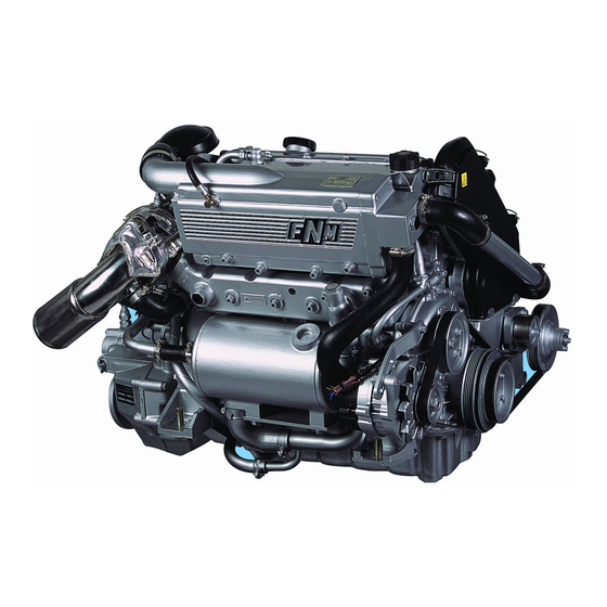
® 1.6 Main components of FNM engine, HPE Series The main components present on HPE marine engines are listed below. Intercooler (except HPEL45): Reduces the temperature of the compressed air from the compressor that flows into the engine intake duct using a bundle of finned tubes crossed by sea water. - Page 20 Oil filler cap: useful in filling the engine oil. (19) Lifting eyes: allow the movement of the engine outside the engine compartment. (20) Engine label position (21) Serial number position on the crankcase (22) Oil drain valve ® HPE Series...
- Page 21 ® ® Figure 1 – FNM HPE 40S/80/80SD/110/110JD – FNM HPEL 80 ® HPE Series...
- Page 22 Figura 2 – FNM ® HPE/P 40/150/150JD/170/170JD/190/190JD – FNM ® HPEL 65/90 ® HPE Series...
- Page 23 Figura 3 – FNM ® HPE/P 100/225/225JD/250/250JD/250H ® HPE Series...
- Page 24 Figure 4 – FNM ® HPE/P 300 ® HPE Series...
- Page 25 Figure 5 – FNM ® HPEL 45 ® HPE Series...
-
Page 26: Engine Delivery
The instrument panel and connection cable must be integral. Any fluids leaks. At the time of shipment engines are bench tested and packaged according to internal ® specifications. FNM is not responsible for damages caused by the carrier/transport company. ® HPE Series... -
Page 27: Using The Fnm ® Engine, Hpe Series
® 2 Using the FNM engine, HPE series ® HPE Series... -
Page 28: Analog Instrument Panel
2.1 Analog Instrument Panel ® If your FNM HPE engine is equipped with an analog instrument panel, it can have an instrument panel complete with key lock, indicators and indicator lights (Figure 7 - Analog instrument panel in separate configuration on page 26), or only an instrument panel with lock key and indicator lights (Figure 7 on page PAGEREF _Ref320107452 \h 26) with separate analog instruments, depending on the type of installation. - Page 29 Each panel has an alarm buzzer that signals the situations of potential danger. For information on the operating status of indicators and indicator lights on the engine panel refer to chapter 3.7.2 - Meaning of the indicators on the analog panel on page 112. ® HPE Series...
- Page 30 Figure 7 - Analog instrument panel in separate configuration Figure 6- Complete analog instrument panel ® HPE Series...
-
Page 31: Digital Instrument Panel
2.2 Digital Instrument Panel ® If your FNM HPE engine is equipped with digital instruments, it can have an instrument panel complete with key lock, lights and indicators (Figure 8- Complete digital instrument panel on page 29), or only an instrument panel with lock key and indicators (Figure 9 - Analog instrument panel in separate configuration on page 29) with separate digital instruments, depending on the type of installation. - Page 32 (7) Transmission oil anomaly indicator light: lights up when the transmission has low oil pressure, or the level of the oil tank is below the minimum. (8) Other indicator lights: Optionals (depend on boat installation). ® HPE Series...
- Page 33 Figure 8- Complete digital instrument panel 2.2.1 The universal CANBUS instrument The digital instrument panel features a LCD display and some buttons that make up the CANBUS universal instrument. The instrument is capable of displaying various information of the engine. ® HPE Series...
- Page 34 It is used during normal operation of the instrument. The screen looks like the image in Figure 10, unless you set the screen of another view as a standard normal mode screen. In normal mode the pressure of the arrow keys allows you increase or decrease the LCD contrast for better viewing. ® HPE Series...
- Page 35 To disable the warning, turn off the buzzer and the alarm lights and press the Mode button . The alarm will recur after 15 minutes if not resolved. Once disabled the alarms they can still be consulted on the last screen of the Selection mode. ® HPE Series...
- Page 36 Consult possible alarm messages that displayed 3.7.3 ® HPE Series...
- Page 37 4 seconds in the Selection mode without pressing any key makes it return to Normal mode. In Selection mode, the arrow keys can be used to display alternative screens containing other parameters monitored by the instrument: ® HPE Series...
- Page 38 35 Hrs WILL DISPLAY TRIM Fuel Level ENGINE and Throttle LOCAL Alarms 33 % When occuring Screen 5 Screen 6 Screen 7 Screen 8 Figure 10 - Possible displays in Selection mode ® HPE Series...
- Page 39 Get information from your installer if it is installed on your boat. Trans Gear: shows the current gear engaged in the transmission. Trans Temp: Indicates the current oil temperature in the transmission. ® HPE Series...
- Page 40 (12) Throttle or Engine Load: show the percentage relative to the position of the throttle. (13) Coolant Tmp: shows the engine coolant temperature. For more information about the displayed information and warning views that may appear, see the paragraph 3.7.3 ® HPE Series...
- Page 41 Use the same key combination to give a confirmation, and the Mode button to go back. The functions which can be modified on the instrument are shown in the figure below. For more information consult the manual of digital instrument (available also on the website www.faria- instruments.com). ® HPE Series...
- Page 42 Function 6 Function 7 Function 8 Function 9 Function 10 Software Id & Select Revision Fuel Self Minigatewa Alarm Test J1939 PGFxxxx Function 13 Function 11 Function 12 Figure 11 - Possible functions of the Setting Mode ® HPE Series...
-
Page 43: First Engine Starting And Sea Trial
4. Verify if you need to lubricate or grease the pinion of the starter and transmission couplings. 5. Check and verify the correct installation of electrical connections. Wrong connection may cause short circuits and cause damage to persons and to the engine. ® HPE Series... - Page 44 2.3.2 First engine start To carry out the actual first engine start: 1. Start the engine, turning the key to position I for some seconds (Figure 12 - Situation of the panel with engine off, key to position I. ® HPE Series...
- Page 45 ® On each occasion in which the engine is used for a long period at high revs, FNM advises not to turn it off at once, but to let it operate at low RPM without gear engaged for at least another two minutes in order to facilitate gradual cooling of the stressed parts (turbine, etc..) avoiding any thermal stress.
-
Page 46: Engine Starting And Stopping Operations
2.4 Engine starting and stopping operations ® Below are listed the operation to carry out for the normal operation of your FNM HPE marine engine. 2.4.1 Preliminary operations at the ordinary engine startup Make sure that the sea water inlet valve is open. The dry run of the sea water pump causes irreparable damage to the impeller and serious damage to the engine after a few minutes of running. - Page 47 (according to the ambient temperature). After few seconds the light turns OFF. It is now possible to start the engine (position II). 2. Start the engine. Turn and hold the key in position (II) and release immediately when you hear that the engine starts. ® HPE Series...
- Page 48 3. Engine functioning While the engine is running (in normal functioning conditions) all the lights and the buzzer must be OFF. Figure 14 – The indicator lights on the panel are turned off when the engine is functioning properly. ® HPE Series...
- Page 49 – on page 112 and paragraph 3.7.4 – Troubleshooting – on page 120. Check and resolve any problems before restarting to avoid serious engine damage. 2.4.3 Engine ordinary use, digital panel To carry out the engine ordinary startup, follow these instructions: ® HPE Series...
- Page 50 (the time depends on ambient temperature). At the end of the preheating phase it turns off. Do not start the engine if the glow plugs alarm (or its indicator) is not turned off. ® HPE Series...
- Page 51 The digital instrument sometimes (as in the case of low battery voltage) can redo the test mode. 3. Engine functioning While the engine is running (in normal functioning conditions) all the lights and the buzzer must be OFF. ® HPE Series...
- Page 52 The digital instrument is in normal operating mode, for default it shows the battery voltage (Volts), the engine coolant temperature (Coolant Tmp). 4. Engine stop Turn counterclockwise the key to position (0) to turn off the engine. ® HPE Series...
- Page 53 Consult paragraph 3.7.3 – Meaning of the indicators on the digital panel – on page 115 and paragraph 3.7.4 – Troubleshooting – on page 120. Check and resolve any problems before restarting to avoid serious engine damage. ® HPE Series...
-
Page 54: Throttle
Figure 21- Mechanical throttle installed on the console (in single and twin-engine Figure 20 - Wall mounted mechanical throttle configuration) ® HPE Series... - Page 55 Moving the lever 16° forward or reverse from the neutral position, the system respectively engages the forward or reverse gear. The accelerator has a stroke of 67° both in forwards or reverse gear. ® HPE Series...
- Page 56 Figure 23- Flexball ® . electronic throttle stroke ® Figure 22 - Flexball electronic throttle for twin-engine. On the lever there is a membrane control keypad consisting of 4 buttons and 4 status indicator LEDs. ® HPE Series...
- Page 57 LED on the left refer to the left engine. 2.5.2.1 Acquisition of the command The electronic throttle allows taking the control of the boat from any position, after the acquisition of control with that position. ® HPE Series...
- Page 58 (with an accuracy of 10 degrees). ; 3. when both levers are synchronized (and therefore the corresponding Engine leds are blinking) it is possible to acquire the command by pressing the Command button for 2 seconds. ® HPE Series...
- Page 59 With both levers in neutral position, press the Engine buttons at the same time for 3 seconds. The command of both engines is now on the right lever. In Synchro mode operation the Warm/Sync and Command LEDs are always lighted on, except for the neutral position where all the LEDS are permanently ON. ® HPE Series...
- Page 60 Simply unscrew the knob completely. This procedure will allow you to control the gearbox manually, using the B levers, and with gas to a minimum. ® HPE Series...
- Page 61 If the LED is blinking the navigation system is in WARM-UP mode that means that Warm/Sync LED the engines can be warmed up because the clutch is disengaged. If the LED is lighted, the system is in Synchro mode. With the right lever both ® HPE Series...
- Page 62 Acquisition of the If you press the Command button for 3 seconds the station takes the command of command the system, only if the control lever is in neutral All LEDs with Situation of system fault fixed light ® HPE Series...
-
Page 63: Notes On Daily Use Of The Engine
2.6 Notes on daily use of the engine ® Please follow these instructions to ensure the daily use of FNM marine engines in total safety: Take care to maintain the engine room dry and well aerated. Residual water in bilge could vaporize and condensate on the engine, vapor created in this process damages the protection varnish. - Page 64 Take care, avoid short-circuits. Short circuit can cause damage to people and engine parts. Toxic and flammable vapors may be created in the battery compartment, aerate the battery compartment. Avoid all risks of fire. ® HPE Series...
-
Page 65: Maintenance Of Fnm ® Engines, Hpe Series
® 3 Maintenance of FNM engines, HPE Series ® HPE Series... -
Page 66: General Information On Maintenance
These interventions are marked by the symbol shown on the side. ® Extraordinary maintenance: performed by qualified staff and authorized FNM service centers, in possession of detailed technical information and specific equipment. Interventions identified by the symbol shown on the side. - Page 67 3.1.2 Safety ® Carefully follow the instructions below for each operations that you are going to do on FNM diesel marine engines. Always wear safety shoes and overalls. Do not wear loose clothing, rings, bracelets and/or necklaces near engines or moving parts.
- Page 68 Avoid maintenance in the presence of electrical voltage: check the effective grounding of all the equipment. During diagnostic operations and maintenance make sure you have hands and feet dry whenever possible and use insulating boards. ® HPE Series...
-
Page 69: Periodic Organization And Frequency Of Maintenance Operations
To avoid voiding the original warranty of your HPE engine always make interventions be carried out on ® the engine by the staff of a FNM authorized service point. For information about individual maintenance operations See section 3.3 - Details of maintenance operations - on page 68. - Page 70 | Operazioni Every week dell’Utente during use FNM First First 30h |Prime Service | Primo Tagliando FNM Tagliando Annuale FNM | Every 100h | Ogni anno | FNM Annual Ogni 100h Every year Service FNM Advanced Service | Every 800h |...
- Page 71 | Operazioni Every week dell’Utente during use FNM First First 30h |Prime Service | Primo Tagliando FNM Tagliando Annuale FNM | Every 100h | Ogni anno | FNM Annual Ogni 100h Every year Service FNM Advanced Service | Every 800h |...
- Page 72 | Operazioni Every week dell’Utente during use FNM First First 30h |Prime Service | Primo Tagliando FNM Tagliando Annuale FNM | Every 100h | Ogni anno | FNM Annual Ogni 100h Every year Service FNM Advanced Service | Every 800h |...
-
Page 73: Details Of Maintenance Operations
2. Extract the oil dipstick from the oil dipstick tube and clean it with blotting paper or similar. 3. Reintroduce the oil dipstick in the guide pipe, take it out and check the level. ® HPE Series... - Page 74 The engine is delivered with the correct amount of oil (MAX) excessive angles can distort the reading. For installation with high angles, make a reference mark on the level dipstick corresponding to the level achieved (with the maximum amount of oil as shipped by the manufacturer). ® HPE Series...
- Page 75 Always verify the good seal of the filter cap to avoid leakage after reassembly. Never refill the coolant circuit with sea water! Be careful when opening the cap of the expansion tank: pressurized liquid may splash out and cause damage to property or persons. ® HPE Series...
- Page 76 Close the sea water intake valve when you dismount the filter. For the filter cleaning: 1. Open the sea water intake cap after closing the valve. Figure 29 - Sea water filter ® HPE Series...
- Page 77 Always verify for the good seal of the filter cap to avoid leakage after reassembly. 3.3.4 Fluids leakage check Ordinary maintenance: made by the boat user and the workshop staff. Periodically check that the engine does not lose any kind of fluid before, during and after its operation. ® HPE Series...
- Page 78 The fuel filter of your engine may be on the engine itself, or be placed on the wall in the engine compartment (HPE/P 300). To drain the fuel filter: 1. Remove the water in fuel presence sensor plug from under the filter. ® HPE Series...
- Page 79 To put the circuit under pressure after the drainage operations turn the ignition key to position (I) and wait that the electric pump stops working, before turning on. ® HPE Series...
- Page 80 Do not smoke near the battery. Flammable gases could be left by the battery. 3.3.6.1 Batteries that are maintenance-free This type of battery is equipped with an indicator of the battery charge status (1). Depending on the color of the indicator you can see the level of battery charge: ® HPE Series...
- Page 81 Never try to refill with any type of fluid with this type of battery. 3.3.6.2 Traditional lead-acid batteries To check the electrolyte level refer to the level marks on the battery side. To refill: 1. Remove the caps on the upper part. ® HPE Series...
- Page 82 4. Replace the caps after the charging cycle. Battery state of charge could influence the engine performance. Avoid discharging excessively the batteries. Grease the battery poles with basic grease periodically. The battery electrolyte status can be measured with a manual densimeter. ® HPE Series...
- Page 83 Replace the anodes if the sacrificial zinc cartridge (see the picture below) is consumed over the 50% (the length of the new part is around 15 mm). The zincs consumption depends on many ® ambient factors and engine connections. FNM uses pure zinc anodes that can be used in the marine environment.
- Page 84 2. Let the engine cool down if it is hot. 3. Prepare a container to collect any leaks. 4. Remove the sensor plug and the sensor from the filter (take care to gasket). Pay attention to possible fuel leakage. ® HPE Series...
- Page 85 9. Bleed the fuel supply circuit. Turn the key to (I) position and wait few seconds until the low pressure electric pump takes the circuit under pressure again. Repeat the operation if necessary. 10. Start the engine and check for any leaks. ® HPE Series...
- Page 86 Ordinary maintenance: made by the boat user and the workshop staff. ® The air filter integrity and cleaning is important for the engine life and performances. FNM engine series air filters are developed for marine applications When cleaning the filter elements only with compressed air, never use pressures above 2 bar to avoid damaging them (filters are dry and need no film of oil on the filtering part).
- Page 87 4. Connect a hose to the drain valve on the sump. The exhaust valve position changes depending on the model of your engine, and is indicated in Chapter 1.6 - Main components of FNM® engine, HPE Series – on page 15.
- Page 88 To check the status of the service belt it is necessary to remove the belts cover from your engine. Follow the instructions: 1. Remove the cover located on the front of the engine. Attention: In case of HPE/P 40/150/150JD/170/170JD/190/190JD and HPEL 65/90 it is also necessary to remove the whole intercooler and its support. ® HPE Series...
- Page 89 3. Verify the belt status. If it is worn, as shown in the figure, it should be replaced. Figure 35 - Worn service belt 4. Reassemble the belt, then tighten the tensioner. 5. Reassemble the belt cover. ® HPE Series...
- Page 90 ® position in paragraph 1.6 - Main components of FNM engine, HPE Series – on page 15. The pump shaft is driven in rotation by the movement of the crankshaft. The function of the sea water pump is to draw water from the sea intake and to put it into circulation in the cooling systems (heat exchangers, exhaust manifold, etc..).
- Page 91 6. Install the new impeller on the grooved shaft. 7. Re-close the pump cap and replace the seal gasket if possible. 8. Open the sea water intake valve. 9. Restart the engine and check for any leaks. Use only original FNM spare parts. ® HPE Series...
- Page 92 After flushing the circuits and after circulated fresh water in the cooling circuit (sea water circulation side), to avoid freezing during long rest of the engine in cold weather conditions, we recommend to: 1. Close the sea water tap 2. Open the sea water filter cap ® HPE Series...
- Page 93 In the case of applications with stern drive follow the same operation using the casings on the suction intakes of the stern drive and sucking from a tank containing the antifreeze mixture. ® HPE Series...
- Page 94 3. Unscrew the zinc anodes on the cover of the water to water exchanger and on the intercooler cover. Facilitate the release of water from the circuit by unscrewing also the anode on the cover of the exhaust manifold. ® HPE Series...
- Page 95 Take care to dismount the oil filter only after removing oil from the sump during the engine oil change operation. 3. Unscrew the filter using the appropriate wrench. 4. Clean the housing with blotting paper or a dry cloth. Lubricate the rubber O-ring seal and the ring seat before remounting the filter cover. ® HPE Series...
- Page 96 7. Turn the engine ON and leave it running at minimum RPM for few minutes until it reaches the working temperature. Increase the speed until reaching the maximum and check the oil pressure level. 8. Check for any leaks. Respect the environment. Exhaust oils are strongly polluting .Follow the local regulations for disposal. ® HPE Series...
- Page 97 ® components of FNM engine, HPE Series – on page 15 to identify the heat exchanger). 5. Dismount the covers of the exchanger. 6. Take care of the seal gaskets, respect their integrity. In any case, replace them if damaged.
- Page 98 2. Drain the circuit unscrewing the anodes as described in section 3.3.13 - Sea water circuit cleaning – on page 87. ® 3. Unscrew the collars of the intercooler hoses (see the section 1.6 - Main components of FNM engine, HPE Series – on page 15 to identify the intercooler) and pull it out. ®...
- Page 99 To clean the exchanger follow the instructions: 1. Stop the engine and close the sea water circuit valve. 2. Empty the sea water circuit by unscrewing the anodes as described in paragraph 3.3.13 - Sea water circuit cleaning – on page 87. ® HPE Series...
- Page 100 3. Remove the sleeves and covers of the fuel exchanger (see paragraph 1.6 - Main components ® of FNM engine, HPE Series – on page 15 to identify it). 4. Clean inside the tubes with a cleaning brush and rinse with water. 5. Reposition the lateral caps (take care to gaskets).
- Page 101 Figure 40 - Electrical wiring of the starter Remove the starter from the housing. Clean the pinion with paper or a clean cloth and grease again. Figure 41- Starter pinion Reassemble the starter and electrical connections. ® HPE Series...
- Page 102 3.3.17 Other advanced maintenance operations Periodic and extraordinary maintenance: The following operations can be performed only by ® qualified and authorized FNM service centers, in possession of detailed technical information and specific equipment. Lubrication of the crankshaft and propeller. Engine alignment and engine mounts retorque.
-
Page 103: Engine Treatment And Maintenance Products
Here are some warnings on the type and quality of products to be used for normal engine treatment. 3.4.1 Maintenance products For the engine maintenance products read and follow the instructions indicated by producers or turn to FNM service. Some products and use are linked to the operating temperatures. Type of fluid Recommended product ®... - Page 104 ® Be careful not to mix different types of engine oil. FNM engine oil equivalent characteristics recommended: Synthetic Multigrade SAE5W40 - ACEA A3-B3-B4, API SL SM CF, MB 229.3, VW 505.00-502.00, BMW Longlife 98. Recommended products: 3.4.2 Fuel characteristics Use only commercially available diesel according to DIN EN 590.
- Page 105 Paint is commonly toxic and flammable, take care during use. Aerate the room and read the producer’s instructions. 3.4.4 Cleaning the panel ® panels are specially designed for the marine environment. Avoid using strong cleaning agents to clean them to prevent damage to surface finishes. ® HPE Series...
-
Page 106: Periods Of Engine Inactivity
After the lubrication circuits washing operation, drain again and fill the engine with new oil, properly added with the proper additives till the oil level indicated by the dipstick is correct. ® HPE Series... - Page 107 ® For the oil treatment FNM advises Bardahl ® Oil Treatment for long storage; while for washing ® and storage it recommends Vanguard Storage 30 oil MIL-L-2104B. 6. After filling with oil and any additive, start the engine and run for about 15 min at minimum RPM to support lubrication of the engine internal mechanism.
- Page 108 18. Store the engine in a well aerated place avoiding humidity and steam to prevent rust forming. ® ® ® 19. For long storage of fuel in tank, FNM advises to use Bardahl DAB or IOSSO Diesel fuel antibacterial additives to prevent the proliferation of algae and deposits.
- Page 109 3. Carry out the engine electronic diagnosis at the first starting after a long period of inactivity. ® 4. -Check the oil level conditions, and if necessary, top up or replace with synthetic oil FNM 5W40. 5. Verify the clogging level and if necessary replace the oil filter.
- Page 110 Viscogrease), and the turbocharger actuator leverages. 13. Keep the engine on for some minutes then turn it off and check again the engine oil and coolant levels. 14. Check for any leaks. The engine is now ready to resume normal operation. ® HPE Series...
-
Page 111: Other Useful Information For Maintenance
The ECU box is equipped with a LED indicators panel to indicate the fuses integrity status. The fuses are on the connectors of the circuit in order to make the replacement procedure easier. In order to replace the fuses, refer to the following table: ® HPE Series... - Page 112 Low pressure fuel pump Fuse F9 Glow plugs main relay Fuse F11 Pin 4 ECU Fuse F10 Pin 5 ECU Fuse F4 Key-on Fuse F3 EOBD Diagnosis Fuse F5 Main relay Fuse F2 Not Used Fuse F1 Not Used ® HPE Series...
-
Page 113: Specifications Of Your Engine
Turbine with variable geometry none turbocarter body Timing system 16-Valve DOHC 20-Valve DOHC 16-Valve DOHC Firing order 1-3-4-2 1-2-4-5-3 1-3-4-2 Idle speed [rpm] 800-850 750-800 750-850 800-850 Max revolution speed 4000-4200 4000 4200 4000-4200 4000-4200 (with load) [rpm] ® HPE Series... - Page 114 Cooling capacity [l] 14,0 Sea water pump flow 90 (24,0 gal/min) 100 (26,6 gal/min) 90 (24,0 gal/min) [l/min] Engine starter 1,3 kW 12V 1,8 kW 12V 2,6 kW 12V 1,3 kW 12V Wet weight (excluding transmission) [kg] ® HPE Series...
- Page 115 3.7.1 Specifications of transmissions The FNM marine engine is generally coupled to high reliability transmission systems. For the use and maintenance of transmissions, please refer to the manufacturer's manual. In the following table you will find the specifications of the transmission oil, as reported by the...
- Page 116 *: The one specified is gear oil. For all other fluids using the stern drive always consult the producer’s manual. For transmissions that are not listed, consult the data provided by the respective producer. ® HPE Series...
- Page 117 At the restart, the battery may not have the necessary Below 12V voltage to start the engine. During operation, the alternator indicator light may turn on. Alternator Lit, engine off It is a condition of normal operation. ® HPE Series...
- Page 118 It indicates the glow plugs preheating required to properly start the Lit, engine off engine. Glow plugs indicator light Indicates a critical engine failure. Contact a FNM ® service point to make Blinking the diagnosis. Indicates the normal operation of the engine.
- Page 119 On, stern drive or gearbox transmission system with proper lubricant, then turn on the engine anomaly indicator installations again. If the problem persists, contact an authorized FNM ® service light point. Indicates leakage of seawater from the saildrive seals. Check the seal On, saildrive installations status.
- Page 120 Turn off the engine immediately. Trim From 0 to 8 units Indicates the position relative to the Trim inclination angle. Oil press Value between 0.7 and 6 bar Indicates the engine oil normal pressure. ® HPE Series...
- Page 121 Indicates the operating pressure of the turbocharger. Throttle or Indicate the percentage corresponding to the position of the throttle Between 0 and 100% Engine Load relative to the engine acceleration. Coolant Temp Between 75°C and 90°C Indicates the temperature of normal engine operation. ® HPE Series...
- Page 122 On, stern drive or gearbox transmission system with proper lubricant, then start the engine again. If anomaly indicator installations the problem persists, contact an authorized FNM® service point. light Indicates leakage of seawater from the Saildrive seals. Check the seal On, Saildrive installations status.
- Page 123 Turn off the engine immediately to prevent short circuits or electrical SYSTEM Amber overloads. Warning Make the engine be checked by an authorized FNM ® service point. Indicates a low voltage (less than 12V) and a problem with the battery or the alternator.
- Page 124 Maintenance Malfunction of the water in fuel sensor Required Check and drain the fuel filter. If the problem persists, make a diagnosis by an authorized FNM ® service point. Indicates excessive pressure of the turbocharger to the engine (greater Alarm: than 3 bar).
- Page 125 Wrong engine electric ground connection Inspect / review Faulty starter-switch or faulty starter-relay. Check / replace. Faulty starter-motor or pinion does not engage. Check / replace the starter-motor. Seized components. Repair. Water in the cylinders. Repair. ® HPE Series...
- Page 126 Intake air filter clogged . Clean/replace Wrong fuel quality or contaminated fuel. Check fuel. Drain and flush fuel tank. Replace with new fuel. Faulty glow plugs. Check / replace. Incorrect lube oil SAE class or quality for ambient Replace. temperature. ® HPE Series...
- Page 127 Leaking in the fuel supply line or fuel injection line Check / replace. Low battery voltage Recharge/ replace Fuel high pressure line regulator fault Replace Faulty fuel injection injectors/pump. Check, replace if required. Clogged exhaust. Check . ® HPE Series...
- Page 128 Check fuel. Drain and flush fuel tank. Replace with new fuel. Oil level too high. Reduce the level. Leak in the air manifold. Dirty intercooler. Check /replace and clean Clogged exhaust. Check/clean. Damaged turbocharger Replace. Dirty injectors Check, replace if required. Transmission. Check. ® HPE Series...
- Page 129 Check and bleed. Fuel filter clogged with water and/or contamination. Check or replace. Leaking in the fuel supply line or fuel injection line Check / replace. Faulty injectors. Check, replace if required. Locked suction valves. Check, replace if required. ® HPE Series...
- Page 130 Incorrect lube oil SAE class or quality for ambient Replace. temperature. Engine overloaded. Check size of propeller. Leak in lubricating oil system. Repair / replace. Oil steams condenser clogged . Replace Turbocharger oil leaks . Replace or repair. ® HPE Series...
- Page 131 Engine overloaded, max. rpm is not reached. Check sizes of propeller and/or boat weight. Engine overloaded, dirty propeller -boat hull. Excessive Check and clean if required. weight on board. Turbocharger actuator blocked Unblock / replace. Faulty turbo compressor. Check / replace. ® HPE Series...
- Page 132 If you find burnt oil traces at the exhaust. Oil level too high . Check . Faulty turbocharger . Check, Repair / Replace . Excessive wear of cylinder / piston, piston rings. Check compression; refurbish engine. ® HPE Series...
- Page 133 3.7.5 Diagnosis All HPE engines are equipped with a plug for electronic diagnosis connection. Make the diagnosis only ® to an authorized FNM service point. ® HPE Series...
-
Page 134: Maintenance Booklet
4 Maintenance booklet ® HPE Series... -
Page 135: Engine Identification Data | Dati Identificativi Del Motore
Engine serial number | Matricola motore: Transmission type | Modello trasmissione: Transmission serial number | Matricola trasmissione: Owner Name | 1° Proprietario: Sea trial date | Data test a mare: Dealer stamp and signature | Timbro e firma del rivenditore: ® HPE Series... -
Page 136: Ordinary And Extraordinary Maintenance Register | Registro Della Manutenzione Periodica Programmata E Straordinaria
2nd Service | ______________ Ordinario (100h) Secondo tagliando Date | Data: Advanced | ______________ Avanzato (800h) Hourmeter | Ore: Ordinary | 3rd service | Terzo ______________ Ordinario (100h) tagliando Date | Data: Advanced | ______________ Avanzato (800h) ® HPE Series... - Page 137 6th service | Sesto ______________ Ordinario (100h) tagliando Date | Data: Advanced | ______________ Avanzato (800h) Hourmeter | Ore: Ordinary | 7th service | ______________ Ordinario (100h) Settimo tagliando Date | Data: Advanced | ______________ Avanzato (800h) ® HPE Series...
- Page 138 10th service | ______________ Ordinario (100h) Decimo tagliando Date | Data: Advanced | ______________ Avanzato (800h) Hourmeter | Ore: Ordinary | 11th service | ______________ Ordinario (100h) Undicesimo Date | Data: Advanced | tagliando ______________ Avanzato (800h) ® HPE Series...
- Page 139 14th service | ______________ Ordinario (100h) Quattordicesimo Date | Data: Advanced | tagliando ______________ Avanzato (800h) Hourmeter | Ore: Ordinary | 15th service | ______________ Ordinario (100h) Quindicesimo Date | Data: Advanced | tagliando ______________ Avanzato (800h) ® HPE Series...
- Page 140 | Firma e Timbro del Centro Assistenza Hourmeter | Ore: ______________ Date | Data: ______________ Hourmeter | Ore: ______________ Date | Data: ______________ Hourmeter | Ore: ______________ Date | Data: ______________ Hourmeter | Ore: ______________ Date | Data: ______________ ® HPE Series...
- Page 141 Notes: ® HPE Series...
- Page 142 Notes: ® HPE Series...
- Page 143 Notes: ® HPE Series...
- Page 144 Notes: ® HPE Series...
- Page 145 Document 6.045.320.1 – HPE Series Owner’s Manual – ENG Language Release Update Date First release 21/03/2012 Added Glow Plug signaling at the pages 27, 28 and 29 31/05/2012 ® HPE Series...
- Page 149 To obtain service: FNM Service C.M.D. Costruzioni Motori Diesel S.p.A. Nucleo Industriale Valle di Vitalba 85020 – Italia Tel. +39 0972 715757 – int. 183 Fax. +39 0972 715696 Email: service.fnm@cmdengine.com Web: www.fnm-marine.com Printed in Italy Order code 6.045.320.1 – Rev. 1 dated 31/05/2012 ©...
Need help?
Do you have a question about the HPE Series and is the answer not in the manual?
Questions and answers