Sign In
Upload
Manuals
Brands
Honeywell Manuals
Measuring Instruments
FlexLine SmartServo 954
Honeywell FlexLine SmartServo 954 Manuals
Manuals and User Guides for Honeywell FlexLine SmartServo 954. We have
1
Honeywell FlexLine SmartServo 954 manual available for free PDF download: Service Manual
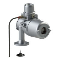
Honeywell FlexLine SmartServo 954 Service Manual (304 pages)
Servo-based level gauge
Brand:
Honeywell
| Category:
Measuring Instruments
| Size: 9.53 MB
Table of Contents
5
Table of Contents
9
General
9
Target Group for This Service Manual
9
Structure of This Manual
9
Trademarks
10
Safety and Security
10
General
10
Safety Conventions
10
Warnings
10
Cautions
11
Safety Instructions
11
EC Declaration of Conformity (For EU)
11
Control Drawings for FM & CSA
11
Users
11
Additional Information
11
Environmental Conditions
12
Liability
12
Labels
13
Personal Safety
13
Warnings and Cautions
13
General
14
Commissioning and Maintenance
15
Accordance to Regulations
15
Explosion Safety
16
Low-Voltage Directive
17
2.10 Security Considerations
20
Principal of Servo Measurement
20
Principle of Measurement
21
Level Measurement
21
Interface Between Two Products
21
Relative Density
22
Servo Gauges
24
System Architecture
24
954 Smartservo Flexline Architecture
25
Flexconn Modules
30
Entities
30
Status Entities
32
Generic Entity
32
Function-Specific Entities
33
HART Smartview Display
33
General
34
Status Entities On HART Smartview
35
Generic Entities On HART Smartview
35
Specific Entities On HART Smartview
36
Engauge Service Tool
37
Status Entities in Engauge
37
Generic Entities in Engauge
37
Board-Specific Entities in Engauge
37
Specific Entities On Engauge
37
Function-Generic Entities On Engauge
38
Service Tools
38
HART Smartview
38
General
38
HART Smartview Versions
38
Connections
39
HART Smartview Controls
41
HART Smartview Menu Structure
55
Engauge
55
Connecting the Engauge Service Tool
56
Using Engauge
57
Installation
58
Commissioning
58
Checks before Starting the Commissioning
59
Installation of Measuring Drum and Displacer
59
Tools
61
Installation of Measuring Drum
62
Installation of Displacer
63
Unlocking (Locking) the Motor Block
64
Configuring Flexconn Boards
64
Introduction
65
Text Conventions
66
Enraf Fieldbus (HCI-BPM)
69
Product Level Measurement (TII-SRV)
105
Miscellaneous
106
Relay Contacts (FII-DO)
116
FCI-HRT, HART Master
144
Average Temperature Measurement (FII-RTD)
156
HART Analog Outputs (HCI-HAO)
167
TRL/2 Fieldbus (HCI-TRL)
196
Integrated Display (TII-LCD)
221
SIL Overfill and Underfill Protection (FII-SIL)
222
Errors
227
Commissioning
227
Proof Testing
227
Entities
239
Configuring the Servo Gauge
240
Alarm Settings
241
Level Calibration
241
Standard Level Calibration
241
Level Calibration with a Tank Top Reference Stop
242
Level Calibration Using the Top of Ball Valve
243
Interface Measurement
245
Advanced Configuration
245
Set Point Compensations
247
Level Compensations
253
Protection and Detection Settings
255
Operation
255
Repeatability Test
255
Lock Test
255
Freeze and Block Commands
256
Unlock
257
Interface Measurement
257
Dip Mode
258
Servo Auto Test
261
Verify Level Calibration
261
Verify Level Calibration against a Tank Top Reference Stop
262
Verify Level Calibration On Top of Ball Valve
263
Maintenance
263
Preventive Maintenance
264
Check Bearings Command
265
Measure Displacer Weight
266
Balance Test
269
Run-Down Test
271
Repeatability Test (Refer to Section 8.1)
271
Instrument Covers
271
Drum Compartment
273
Removing the Measuring Drum
274
Replacing the Drum Bearings
275
The Electronic Compartment
275
Detailed Description
276
Dismantling the Electronic Compartment
279
Calibrating Force Transducer
283
Synchronizing the Reference Encoder
284
10 954 Density Option
284
10.1 Introduction
284
Functional Description
285
Principle of Operation
285
Commissioning
285
Installation On the Tank
285
Calibration of the 954 Level Gauge
286
Setting of Density Items
287
Settings for a Tank Profile Measurement (Command Tank Profile)
288
Settings for an Interface Profile Measurement (Command Interface Profile)
289
Corrections
289
10.3 Operation
289
Manual Input
289
Data Items, Commands and Error Codes
290
10.4 Maintenance and Trouble Shooting
290
Maintenance
290
Trouble Shooting
292
Trouble Shooting
292
11.1 Problems with Displacer Movement
292
11.2 Status Codes
293
Informational Status Codes
294
Warnings
295
Errors
298
12 Appendix A: Article And Part Numbers
301
13 Appendix B: Additional Information On Displacers
303
14 Appendix C: ASCII Table
Advertisement
Share and save
Advertisement
Related Products
Honeywell AirAlert 96d
Honeywell 90DM4
Honeywell VoyagerGS 9590 Series
Honeywell Voyager 9520
Honeywell Voyager 9540
Honeywell Dolphin 9500
Honeywell Dolphin 9951
Honeywell 998MX
Honeywell 995
Honeywell ControlEdge 900K01-0201
Honeywell Categories
Thermostat
Controller
Security Camera
Control Unit
Accessories
More Honeywell Manuals
×
Login
Sign In
OR
Sign in with Facebook
Sign in with Google
×
Upload manual
Upload from disk
Upload from URL