Sign In
Upload
Manuals
Brands
Comtech EF Data Manuals
Network Router
Vipersat CDD-562L
Comtech EF Data Vipersat CDD-562L Manuals
Manuals and User Guides for Comtech EF Data Vipersat CDD-562L. We have
4
Comtech EF Data Vipersat CDD-562L manuals available for free PDF download: Installation And Operation Manual, User Manual
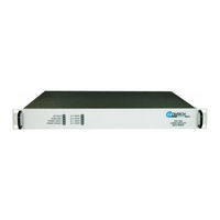
Comtech EF Data Vipersat CDD-562L Installation And Operation Manual (254 pages)
Demodulator with IP Module
Brand:
Comtech EF Data
| Category:
Control Unit
| Size: 8 MB
Table of Contents
Table of Contents
5
Table of Contents
6
About this Manual
15
Conventions and References
15
Preface
15
Reporting Comments or Suggestions Concerning this Manual
15
Warnings, Cautions, and Notes
15
Electrical Safety and Compliance
16
Grounding
16
Metric Conversion
16
Patents and Trademarks
16
Recommended Standard Designations
16
Safety and Compliance
16
Electrical Installation
17
European Union Radio Equipment and Telecommunications Terminal Equipment (R&TTE) Directive (1999/5/EC) and en 301 489-1
17
Operating Environment
17
European Union Low Voltage Directive (LVD) (2006/95/EC)
18
CE Mark
19
European Union Rohs Directive (2002/95/EC)
19
European Union Telecommunications Terminal Equipment Directive (91/263/EEC)
19
Limitations of Warranty
20
Warranty Policy
20
Exclusive Remedies
21
Contacting Comtech EF Data
22
Getting Help
22
Returning a Product for Upgrade or Repair
23
Chapter 1. INTRODUCTION
25
Overview
25
Figure 1-1. CDD-562L L-Band Satellite Dual Demodulator
25
Figure 1-2. CDD-564/564L 70/140 Mhz / L-Band Satellite Quad Demodulators
25
Functional Description
27
Figure 1-3. CDD-5Xx Block Diagrams
28
Features
29
Physical Description
29
Major Assemblies
29
Interoperability/Compatibility
29
Dimensional Envelopes
30
Figure 1-4. CDD-562L Dimensional Envelope
30
Figure 1-5. CDD-564/564L Dimensional Envelope
31
Physical Features
32
Front Panel
32
Figure 1-6. Front Panel Views
32
Rear Panel
33
Figure 1-7. Rear Panel Views
33
Data Interfaces
34
Updating Demodulator Firmware
34
Fully Accessible System Topology (FAST)
34
Summary of Specifications
36
Demodulator
36
70/140 Mhz (CDD-564 Only)
36
L-Band (CDD-562L, CDD-564L)
37
Low Noise Block Converter (LNB) Support (CDD-564L Only)
38
Environmental and Physical
38
Network Protocols
38
BER (Bit Error Rate)
39
Chapter 2. INSTALLATION and STARTUP
41
Unpacking and Inspecting the Shipment
41
Figure 2-1. Unpacking and Inspecting the Shipment
41
Rack-Mounting the CDD-56X
42
Figure 2-2. Installation into a Rack Enclosure
43
2.2.1 Installing the Optional Rear-Mounting Support Brackets Kit
44
Figure 2-3. Optional Rear-Mounting Support Brackets Kit Installation
44
Initial Configuration
45
Connecting External Cables
45
Chapter 3. REAR PANEL CONNECTOR PINOUTS
47
CDD-56X Rear Panel Overview
47
Figure 3-1. CDD-56X Rear Panel View
47
CDD-56X Cable Connections
48
Table 3-1. Rear Panel External Cable Connections
48
Rx if Connections
49
CDD-562L and CDD-564L L-Band Chassis Rx Input
49
CDD-564 70/140 Mhz Chassis Rx Input
49
Terrestrial Data Connection - 10/100 Ethernet (RJ-45 Traffic/M&C Port)
50
Utility Connections
51
Remote Control (DB-9M)
51
Console (RJ-11 Async-Serial Port)
51
CDD-56X Ground and Power Connections
52
Chassis Ground Interface
52
Figure 3-2. CDD-56X Typical Chassis Ground Interface
52
240V Alternating Current (AC) Power Interface (Standard)
53
AC Operation - Applying Power
53
Figure 3-3. CDD-56X AC Power Interface
53
Figure 3-4. Applying AC Power to the CDD-56X
53
AC Operation - Replacing Fuses
54
Figure 3-5. Replacing CDD-56X AC Fuses
54
Direct Current (DC) Power Interface (Optional)
55
DC Operation - Applying Power
55
Figure 3-6. CDD-56X DC Power Interface
55
Figure 3-7. Applying DC Power to the CDD-56X
55
DC Operation - Replacing Fuses
56
Figure 3-8. Replacing CDD-56X DC Fuses
56
Chapter 4. IP MODULE ETHERNET INTERFACE
57
Introduction
57
Standard Features
57
10/100 Baset Ethernet Interface
58
Powerful Network Management
58
Remote Firmware Update Via FTP
58
Configuration Backup and Restore Via FTP
59
Event Logging to Capture All Demodulator Activity
59
Detailed Statistics of IP Traffic
59
IGMP Support for Multicast
59
Static IP Routing for Unicast and Multicast
59
Demodulator Features
59
3Xdes Encryption with Ability to Change Keys
60
IP Header Compression
60
Payload Compression
61
ADLC Vs LZS Compression Comparison
61
IP Module Specifications
62
Supported Rfcs and Protocols
62
CDD562L/564/564L Compatibility
62
Typical IP Module Operational Setups
63
IP Module Working Modes
63
Router Working Mode - Point-To-Point
65
Figure 4-1. (CDD-562L) Router Mode Point-To-Point Diagram
65
Figure 4-2. (CDD-564/564L) Point-To-Point Router Working Mode Diagram
66
Router Working Mode - Point-To-Multipoint
67
Chapter 5. UPDATING FIRMWARE
71
Updating Firmware Via the Internet
71
About Firmware Files, Naming, Versions and Formats
73
Ethernet FTP Upload Procedure
74
Getting Started: Preparing for the Firmware Download
74
Downloading and Extracting the Firmware Update
76
Bulk Firmware FTP Upload Procedure
78
Chapter 6. Ethernet-Based Remote Product Management
81
Introduction
81
Ethernet Management Interface Protocols
81
SNMP Interface
81
Management Information Base (MIB) Files
82
6.3.2 SNMP Community Strings
82
SNMP Traps
83
Mib-II
84
Private MIB
84
Administration Group
84
Access Lists Subgroup
84
Features Subgroup
84
Table 6-1. MIB-II Support
84
3Xdes Decryption Subgroup
85
SMTP Subgroup
85
SNMP Traps Subgroup
85
Interface Group
85
Ethernet Interface Subgroup
85
Demodulator Interface Subgroup
85
Route Table Group
85
Protocols Group
85
IGMP Subgroup
86
Maintenance Group
86
Statistics Group
86
IP Routing Statistics Subgroup
86
Ethernet Statistics Subgroup
86
Satellite Statistics Subgroup
86
Demodulator Configuration Group
86
Rx Parameters
86
Alarm Mask Parameters
87
Reference Parameters
87
LNB Parameters
87
Monitor Group
87
Unit Monitor
87
Rx Monitor
87
LNB Monitor
87
Stored Events Log
87
Stored Statistics
87
Utilities Group
87
Telnet Interface
88
Telnet Operation Via Hyperterminal
88
HTTP (Web Server) Interface
90
Chapter 7. QUICK START GUIDE
93
Introduction
93
Getting Started
94
7.2.1 Equipment List
94
7.2.2 Basic Equipment Setup
94
7.2.3 Transmit and Receive if Configuration
95
7.2.4 Serial Console Port Command Line Interface (CLI) Configuration
95
7.2.5 Restoring Factory Default Configuration
97
Router Mode - Point-To-Point System Configuration
98
7.3.1 PC Configuration
98
7.3.2 Set CDM-IP Modems to Router Mode Operation
99
7.3.3 Set CDD-56X Demodulator to Router Mode Operation
100
Set IP Address(Es)
101
7.3.5 Set IP Stack des Select Key to Clearroute Table
101
Troubleshooting the IP Module
103
7.4.1 Router Mode Troubleshooting
104
Advertisement
Comtech EF Data Vipersat CDD-562L User Manual (176 pages)
Satellite Network Demodulator Router, Vipersat CDD-56X Series
Brand:
Comtech EF Data
| Category:
Network Router
| Size: 3 MB
Table of Contents
General
8
List of Figures
11
List of Tables
13
User Guide
3
Document Revision History
5
Table of Contents
7
Chapter 1 - General
15
Chapter 2 - Quick Start Configuration
15
How to Use this Manual
15
Manual Organization
15
Chapter 3 - Using the Command Line
16
Appendix A - Network Addressing
16
Appendix B - Automatic Switching
16
Appendix C - Dynamic Power Control1-2
16
Appendix D - ECM Migration
16
Appendix E - Glossary
16
Conventions and References
16
Product Description
18
Demodulator Features
18
Introduction
18
Router Features
18
Dynamic SCPC (Dscpc)
19
Network and Bandwidth Management
19
Header Decompression
20
Single Hop on Demand
20
Stdma
20
Turbo Product Coding
20
1.6.11/2.6.11 Release
21
Data Decryption
21
Dynamic Entry Channel Mode
21
New in this Release
21
Payload Decompression
21
Customer Support
22
Contact Information
22
Reader Comments / Corrections
22
Return Material Authorization
22
Introduction
23
Quick Start Configuration
23
Initial Configuration
24
Terminal Connection
24
Network Role
24
Setting Vipersat CDD-56X Operating Parameters
25
Set the Feature Configuration
25
Figure 2-1 Main Menu Screen
26
Figure 2-2 Administration Screen
26
Figure 2-5 Working Mode Dialog
28
Set the IP Address
28
Configure the Route Table
29
Figure 2-6 Ethernet Interface Screen
29
Routing in a Vipersat Network
29
Creating the Routes
30
Figure 2-7 Configuring the Route Table Screen
31
Set the Satellite Demod Configuration
31
Figure 2-8 Rx Configuration Screen
32
Figure 2-9 Vipersat Configuration Screen (Hub)
32
Set the Vipersat Configuration
32
Using the Command Line Interface
35
Menu Descriptions
37
Main Menu
37
Administration
37
Figure 3-1 Main Menu Screen
37
Figure 3-2 Administration Screen
38
Figure 3-3 Working Mode Dialog
38
Feature Configuration
39
Figure 3-4 Feature Configuration Screen
39
Vipersat Feature Codes
39
Figure 3-5 FAST Feature Code Dialog
40
Vipersat Auto Switching
40
Vipersat Management
40
Vipersat STDMA
40
Vipersat File Streamer
41
Vipersat Configuration
42
STDMA Mode
42
Figure 3-7 STDMA Screen
43
Figure 3-8 STDMA Screen (Hub/Remote, SCPC)
43
Stdma
43
Figure 3-9 Hub Type Prompt
44
Hub Type
44
STDMA Tx Rate
44
Dynamic Cycle
45
Dynamic Slot
45
Fixed
45
Gir
45
Ecmv2
46
Entry Channel
46
Ecmv2 Mode
47
Figure 3-10 Ecmv2 Mode Prompt
47
Figure 3-11 Group ID Prompt
48
Group ID
48
STDMA Max Power Hunt
48
Burstmap Multicast IP
49
Figure 3-12 STDMA Max Power Hunt Prompt
49
Low Data Rate Fast Acquisition
49
Cycles Per Burst Map
50
Figure 3-14 Outbound IP Prompt
50
Outbound IP
50
Slot Guardband
51
Figure 3-15 Cycles Per Burst Map Prompt
51
Figure 3-16 Slot Guardband Prompt
51
Slot Preamble Length
52
Slot Data Length
52
Figure 3-17 Slot Preamble Length Prompt
52
Nominal Data Length
53
Maximum Data Length
53
Minimum Data Length
54
Total Slot Count
54
Figure 3-20 Maximum Data Length Prompt
54
Figure 3-21 Minimum Data Length Prompt
54
Slot Cycle Length
55
Slot Start in Cycle
55
Set Remotes
55
Figure 3-22 Total Slot Count Prompt
55
Adding a Remote to the STDMA Group
56
Figure 3-23 STDMA Remotes Menu Screen
56
Figure 3-24 Remote Name and IP Address Prompt
56
Base
57
Figure 3-25 Base Remote Display Prompt
57
Remote Count
57
Figure 3-26 STDMA Remote Policies Screen
58
Set Remote Policies
58
Figure 3-27 GIR Remote Policies Prompt
59
Figure 3-28 Entry Channel Switch Rates Screen
59
Delete Remote
60
Figure 3-30 Global SCPC Data Rate Prompt
60
Figure 3-31 Global Switch Type Prompt
60
Enable/Disable Remote
61
Figure 3-32 Delete Remote Prompt
61
Figure 3-34 View Remote(S) Screen
61
View Remote(S)
61
Remove Retry Timeout
62
Remove Timeout
62
LNB lo Frequency
63
Satellite Frequency Conversion
63
Figure 3-37 LNB lo Frequency Prompt
63
Figure 3-38 Satellite Frequency Conversion Prompt
63
STDMA Statistics
64
Figure 3-39 STDMA Statistics Screen (Hub)
64
Figure 3-40 STDMA Statistics Screen (Remote)
64
Stats Accumulation Window
64
Clear
65
Show Hub Statistics
65
Figure 3-41 Stats Accumulation Window Prompt
65
Figure 3-42 Show Hub Statistics Screen
65
STDMA/SCPC Automatic Switching
66
Auto Switching
67
Figure 3-43 Automatic Switching Screen
67
Current WAN Transmit Mode
68
Load Switching
68
STDMA Slot Capacity
68
Figure 3-44 STDMA Slot Capacity Prompt
68
STDMA Switch Delay
69
Percent Allocation
69
Keep Alive Timer for Carrier Inhibit
70
Hitless Switching Parameters
70
Figure 3-47 Keep Alive Timer for Carrier Inhibit
70
Delay for Demod
71
Delay for Mod
71
Figure 3-48 Hitless Switching Screen
71
Locktimes
71
Apply Delay Values
72
SOTM Update
72
Figure 3-49 Set Locktime Prompt
72
Figure 3-50 Unit Role Prompt
72
Unit Role
72
Expansion Unit
73
Figure 3-51 Expansion Unit Prompt
73
Network ID
73
Figure 3-52 Network ID Prompt
74
Figure 3-53 Unit Name Prompt
74
Receive Multicast Address
74
Unit Name
74
Figure 3-54 Receive Multicast IP Address Prompt
75
Figure 3-55 Managing IP Address Prompt
75
Managing IP Address
75
Management Security
76
Home State Revert
78
Dynamic Power Control Configuration
78
Figure 3-58 DPC Configuration Screen
79
Figure 3-59 DPC Configuration Screen
79
DPC Enabled
80
Figure 3-60 Speed up Ebno Prompt
80
Speed up Ebno
80
Target DPC Address
80
Set Home State Parameters
81
Force Modem to Home State
82
Set Current Configuration as Home State
82
Figure 3-63 Force Modem to Home State Warning
83
Figure 3-64 Receive Frequency Prompt
83
Receive Data Rate
83
Receive Frequency
83
STDMA State
83
Figure 3-65 Receive Data Rate Prompt
84
Figure 3-66 Receive FEC Type Prompt
84
Figure 3-67 Receive Coding Rate Prompt
84
Receive Coding Rate
84
Receive FEC Type
84
Receive Modulation Type
85
Vipersat Summary
85
Vipersat Migration
86
UDP Port Base Address
87
Alerts
87
Figure 3-70 Vipersat Migration Prompt
87
Figure 3-71 UDP Port Base Address Prompt
87
Primary Heart Beat
78
(Cli)
35
General
35
Common Screen Commands
36
Demod Select
36
Exit
36
Save Parameters to Permanent Storage
36
Telnet Logout
36
Appendix A Network Addressing
89
Introduction
89
Appendix A Figures
90
Figure A-1 the Seven OSI Protocol Layers
90
The OSI Reference Model
90
Layers 1 - 3
90
Binary Math
92
Figure A-2 Bits and Bytes
92
Figure A-3 Binary to Decimal Conversion
92
IP Addressing
94
IP Address Classes
94
Class a
94
Class B
94
Class C
95
Class D
95
Figure A-4 IP Address Classes A, B, C
95
Class E
96
Network Address Translation (NAT
96
Private Network IP Addresses
96
Subnets
96
Subnet Mask
97
Network Segments
98
Figure A-8 Network Segments
98
Default Gateways
99
MAC Addresses
99
Figure A-8 Network Segments . . . . . . . . . . . .A-10 Appendix C Figures
100
Figure A-10 Network Node MAC Addresses
100
Comtech EF Data Vipersat CDD-562L User Manual (150 pages)
Vipersat CDD-56X Series Satellite Network Demodulator Router
Brand:
Comtech EF Data
| Category:
Network Router
| Size: 5 MB
Table of Contents
User Guide
1
Document Revision History
5
Table of Contents
7
List of Figures
11
List of Tables
13
Chapter 1 - General
15
Chapter 2 - Quick Start Configuration
15
How to Use this Manual
15
Manual Organization
15
Chapter 3 - Using the Command Line
16
Appendix A - Network Addressing
16
Appendix B - Automatic Switching
16
Appendix C - Dynamic Power Control1-2
16
Appendix D - Network Migration
16
Appendix E - Glossary
16
Conventions and References
16
Product Description
17
Demodulator Features
17
Introduction
17
Dynamic SCPC (Dscpc)
18
Network and Bandwidth Management
18
Router Features
18
Single Hop on Demand
19
Stdma
19
1.5.4 Release
20
Data Decryption
20
Header Decompression
20
New DPC (Dynamic Power Control) Enhancements
20
New in this Release
20
Payload Decompression
20
Turbo Product Coding
20
Auto Home State Failsafe
21
Hitless Switching
21
STDMA Power Hunt
21
UDP Port Base Address
21
VMS Registration and Managing Address
21
SOTM (Satellite on the Move)
22
Customer Support
22
Contact Information
22
Return Material Authorization
22
Reader Comments / Corrections
23
Introduction
25
Quick Start Configuration
25
Initial Configuration
26
Terminal Connection
26
Network Role
26
Setting Vipersat CDD-56X Operating Parameters
27
Set the Feature Configuration
27
Figure 2-1 Main Menu Screen
28
Figure 2-2 Administration Screen
28
Figure 2-3 Feature Configuration Screen
29
Figure 2-4 FAST Feature Code Dialog
29
Set the IP Address
30
Configure the Route Table
31
Figure 2-6 Ethernet Interface Screen
31
Routing in a Vipersat Network
31
Creating the Routes
32
Figure 2-7 Configuring the Route Table Screen
33
Set the Satellite Demod Configuration
33
Figure 2-8 Rx Configuration Screen
34
Set the Vipersat Configuration
34
Figure 2-9 Vipersat Configuration Screen (Hub)
35
Using the Command Line Interface
37
Menu Descriptions
39
Main Menu
39
Administration
39
Figure 3-1 Main Menu Screen
39
Figure 3-2 Administration Screen
40
Figure 3-3 Working Mode Dialog
40
Feature Configuration
41
Figure 3-4 Feature Configuration Screen
41
Vipersat Feature Codes
41
Figure 3-5 FAST Feature Code Dialog
42
Vipersat Auto Switching
42
Vipersat Management
42
Vipersat STDMA
42
Vipersat File Streamer
43
Vipersat Configuration
44
STDMA Mode
44
Figure 3-7 STDMA Screen
45
Figure 3-8 STDMA Screen (Hub/Remote, SCPC)
45
Stdma
45
Figure 3-9 Hub Type Prompt
46
Hub Type
46
STDMA Tx Rate
46
Dynamic Cycle
47
Dynamic Slot
47
Fixed
47
Gir
47
Entry Channel
48
Group ID
48
STDMA Power Hunt
49
Low Data Rate Fast Acquisition
49
Figure 3-10 Group ID Prompt
49
Burstmap Multicast IP
50
Outbound IP
50
Figure 3-11 Burstmap Multicast IP Prompt
50
Cycles Per Burst Map
51
Slot Guardband
51
Figure 3-13 Cycles Per Burst Map Prompt
51
Slot Preamble Length
52
Figure 3-14 Slot Guardband Prompt
52
Slot Data Length
53
Nominal Data Length
53
Figure 3-16 Slot Data Length Prompt
53
Maximum Data Length
54
Minimum Data Length
54
Figure 3-17 Nominal Data Length Prompt
54
Figure 3-18 Maximum Data Length Prompt
54
Slot Cycle Length
55
Slot Start in Cycle
55
Set Remotes
55
Figure 3-19 Minimum Data Length Prompt
55
Adding a Remote to the STDMA Group
56
Figure 3-20 STDMA Remotes Menu Screen
56
Figure 3-21 Remote Name and IP Address Prompt
56
Base
57
Figure 3-22 Base Remote Display Prompt
57
Remote Count
57
Set Remote Policies
57
Figure 3-23 STDMA Remote Policies Screen
58
Figure 3-24 GIR Remote Policies Prompt
58
Figure 3-25 Entry Channel Switch Rates Screen
59
Delete Remote
60
Enable/Disable Remote
60
Figure 3-27 Global SCPC Data Rate Prompt
60
Figure 3-28 Global Switch Type Prompt
60
Figure 3-29 Delete Remote Prompt
60
Figure 3-31 View Remote(S) Screen
61
Remove Timeout
61
View Remote(S)
61
Figure 3-32 Remove Timeout Prompt
62
Figure 3-33 Remove Retry Timeout Prompt
62
Remove Retry Timeout
62
STDMA Statistics
63
Figure 3-34 STDMA Statistics Screen (Hub)
63
Figure 3-35 STDMA Statistics Screen (Remote)
63
Clear
64
Stats Accumulation Window
64
Show Hub Statistics
64
Figure 3-36 Stats Accumulation Window Prompt
64
Figure 3-37 Show Hub Statistics Screen
64
STDMA/SCPC Automatic Switching
65
Auto Switching
66
Figure 3-38 Automatic Switching Screen
66
Current WAN Transmit Mode
67
Load Switching
67
STDMA Slot Capacity
67
Figure 3-39 STDMA Slot Capacity Prompt
67
STDMA Switch Delay
68
Percent Allocation
68
Figure 3-40 STDMA Switch Delay Prompt
68
Figure 3-41 Percent Allocation Prompt
68
Keep Alive Timer for Carrier Inhibit
69
Hitless Switching Parameters
69
Figure 3-42 Keep Alive Timer for Carrier Inhibit
69
Delay for Demod
70
Delay for Mod
70
Figure 3-43 Hitless Switching Screen
70
Locktimes
70
Apply Delay Values
71
SOTM Update
71
Figure 3-44 Set Locktime Prompt
71
Figure 3-45 Unit Role Prompt
71
Unit Role
71
Expansion Unit
72
Figure 3-46 Expansion Unit Prompt
72
Network ID
72
Receive Multicast Address
73
Managing IP Address
74
Figure 3-49 Receive Multicast IP Address Prompt
74
Figure 3-50 Managing IP Address Prompt
74
Primary Heart Beat
75
Home State Revert
75
Dynamic Power Control Configuration
76
DPC Enabled
77
Figure 3-51 DPC Configuration Screen
77
Figure 3-52 DPC Configuration Screen
77
Figure 3-53 Speed up Ebno Prompt
78
Speed up Ebno
78
Target DPC Address
78
Set Home State Parameters
79
Set Current Configuration as Home State
80
Figure 3-56 Force Modem to Home State Warning
81
Figure 3-57 Receive Frequency Prompt
81
Force Modem to Home State
81
Receive Frequency
81
STDMA State
81
Receive Coding Rate
82
Receive Data Rate
82
Receive FEC Type
82
Receive Modulation Type
83
Vipersat Summary
83
Figure 3-60 Receive Coding Rate Prompt
83
Figure 3-61 Receive Modulation Type Prompt
83
Figure 3-62 Vipersat Summary Screen
84
Vipersat Migration
85
UDP Port Base Address
85
Figure 3-63 Vipersat Migration Prompt
85
Figure 3-64 UDP Port Base Address Prompt
86
Unit Name
73
(Cli)
37
General
37
Common Screen Commands
38
Demod Select
38
Exit
38
Save Parameters to Permanent Storage
38
Telnet Logout
38
Advertisement
Comtech EF Data Vipersat CDD-562L User Manual (144 pages)
Satellite Network Demodulator Router
Brand:
Comtech EF Data
| Category:
Network Router
| Size: 4 MB
Table of Contents
User Guide
1
Table of Contents
7
General
8
List of Figures
11
List of Tables
13
How to Use this Manual
15
Manual Organization
15
Chapter 1 - General
15
Chapter 2 - Quick Start Configuration
15
Chapter 3 - Using the Command Line
16
Appendix A - Network Addressing
16
Appendix B - Automatic Switching
16
Appendix C - Dynamic Power Control1-2
16
Appendix D - Network Migration
16
Appendix E - Glossary
16
Conventions and References
16
Product Description
18
Demodulator Features
18
Introduction
18
Router Features
18
Dynamic SCPC (Dscpc)
19
Network and Bandwidth Management
19
Header Decompression
20
Single Hop on Demand
20
Stdma
20
Turbo Product Coding
20
1.5.3 Release
21
Data Decryption
21
New in this Release
21
New Qos Features
21
New Redundancy Features
21
Payload Decompression
21
Automatic Home State Control (Remote Unit)
22
Burst Fast Acquisition Timing (BFAT)
22
Parameter File Consolidation
22
RTP Inactivity Timeout
22
STDMA Slot Quantization
22
Vipersat File Streaming (VFS)
22
ECM User Defined Switch Type
23
Customer Support
24
Contact Information
24
Reader Comments / Corrections
24
Return Material Authorization
24
Quick Start Configuration
25
Introduction
25
Initial Configuration
26
Terminal Connection
26
Network Role
26
Setting Vipersat CDD-56X Operating Parameters
27
Set the Feature Configuration
27
Figure 2-1 Main Menu Screen
28
Figure 2-2 Administration Screen
28
Figure 2-3 Feature Configuration Screen
29
Figure 2-4 Feature and Unlock Code Dialog
29
Set the IP Address
30
Configure the Route Table
31
Figure 2-6 Ethernet Interface Screen
31
Routing in a Vipersat Network
31
Creating the Routes
32
Figure 2-7 Configuring the Route Table Screen
33
Set the Satellite Demod Configuration
33
Figure 2-8 Rx Configuration Screen
34
Set the Vipersat Configuration
34
Using the Command Line Interface (CLI)
37
General
37
Common Screen Commands
38
Demod Select
38
Exit
38
Save Parameters to Permanent Storage
38
Telnet Logout
38
Menu Descriptions
39
Main Menu
39
Administration
39
Figure 3-1 Main Menu Screen
39
Feature Configuration
40
Figure 3-2 Administration Screen
40
Figure 3-3 Feature Configuration Screen
40
Figure 3-4 Feature and Unlock Code Dialog
41
Vipersat Feature Codes
41
Vipersat Auto Switching
42
Vipersat File Streamer
42
Vipersat Management
42
Vipersat STDMA
42
Vipersat Configuration
44
STDMA Mode
44
Figure 3-6 STDMA Screen
45
Figure 3-7 STDMA Screen (Hub/Remote, SCPC)
45
Figure 3-8 Hub Type Prompt
46
Hub Type
46
Stdma
46
STDMA Tx Rate
46
Dynamic Cycle
47
Dynamic Slot
47
Fixed
47
Gir
47
Entry Channel
48
Group ID
48
Burstmap Multicast IP
49
Figure 3-9 Group ID Prompt
49
Low Data Rate Fast Acquisition
49
Cycles Per Burst Map
50
Figure 3-10 Burstmap Multicast IP Prompt
50
Figure 3-11 Outbound IP Prompt
50
Outbound IP
50
Slot Guardband
51
Slot Preamble Length
51
Figure 3-12 Cycles Per Burst Map Prompt
51
Figure 3-13 Slot Guardband Prompt
51
Slot Data Length
52
Figure 3-14 Slot Preamble Length Prompt
52
Figure 3-15 Slot Data Length Prompt
52
Nominal Data Length
53
Maximum Data Length
53
Figure 3-16 Nominal Data Length Prompt
53
Minimum Data Length
54
Slot Cycle Length
54
Figure 3-17 Maximum Data Length Prompt
54
Figure 3-18 Minimum Data Length Prompt
54
Slot Start in Cycle
55
Set Remotes
55
Adding a Remote to the STDMA Group
55
Figure 3-19 STDMA Remotes Menu Screen
55
Base
56
Figure 3-20 Remote Name and IP Address Prompt
56
Figure 3-21 Base Remote Display Prompt
57
Figure 3-22 STDMA Remote Policies Screen
57
Remote Count
57
Set Remote Policies
57
Figure 3-23 GIR Remote Policies Prompt
58
Figure 3-24 Entry Channel Switch Rates Screen
58
Delete Remote
59
Enable/Disable Remote
60
Figure 3-28 Delete Remote Prompt
60
Figure 3-30 View Remote(S) Screen
60
View Remote(S)
60
Remove Retry Timeout
61
Remove Timeout
61
STDMA Statistics
62
Figure 3-33 STDMA Statistics Screen (Hub)
62
Clear
63
Stats Accumulation Window
63
Show Hub Statistics
63
Figure 3-34 STDMA Statistics Screen (Remote)
63
Figure 3-35 Stats Accumulation Window Prompt
63
Figure 3-36 Show Hub Statistics Screen
64
STDMA/SCPC Automatic Switching
65
Auto Switching a Hub CDD-56X
65
Auto Switching
66
Current WAN Transmit Mode
66
Load Switching
66
Figure 3-38 STDMA Slot Capacity Prompt
67
STDMA Slot Capacity
67
STDMA Switch Delay
67
Figure 3-39 STDMA Switch Delay Prompt
68
Figure 3-40 Percent Allocation Prompt
68
Percent Allocation
68
Time for Carrier Inhibit
68
Unit Role
69
Expansion Unit
69
Figure 3-41 Unit Role Prompt
69
Figure 3-42 Expansion Unit Prompt
69
Network ID
70
Unit Name
70
Figure 3-43 Network ID Prompt
70
Receive Multicast Address
71
Figure 3-44 Unit Name Prompt
71
Figure 3-45 Receive Multicast IP Address Prompt
71
Managing IP Address
72
Primary Heart Beat
72
Home State Revert
72
Figure 3-46 Managing IP Address Prompt
72
Dynamic Power Control Configuration
73
DPC Enabled
74
Figure 3-47 DPC Configuration Screen
74
Figure 3-48 DPC Configuration Screen
74
Speed up Ebno
75
Target DPC Address
75
Figure 3-49 Speed up Ebno Prompt
75
Set Home State Parameters
76
Figure 3-50 Target DPC Address Prompt
76
Figure 3-52 Force Modem to Home State Warning
77
Force Modem to Home State
77
Set Current Configuration as Home State
77
STDMA State
77
Receive Frequency
78
Figure 3-53 Receive Frequency Prompt
78
Figure 3-54 Receive Data Rate Prompt
78
Receive Data Rate
78
Receive Coding Rate
79
Receive FEC Type
79
Receive Modulation Type
79
Figure 3-57 Receive Modulation Type Prompt
80
Figure 3-58 Vipersat Summary Screen
80
Vipersat Summary
80
Figure 3-59 Vipersat Migration Prompt
81
Vipersat Migration
81
Network Addressing
83
Introduction
83
Appendix A Figures
84
Figure A-1 the Seven OSI Protocol Layers
84
The OSI Reference Model
84
Layers 1 - 3
84
Binary Math
86
Figure A-2 Bits and Bytes
86
Figure A-3 Binary to Decimal Conversion
86
IP Addressing
88
IP Address Classes
88
Class a
88
Class B
88
Class C
89
Class D
89
Figure A-4 IP Address Classes A, B, C
89
Class E
90
Network Address Translation (NAT
90
Private Network IP Addresses
90
Subnets
90
Figure A-5 NAT Router Example
90
Subnet Mask
91
Network Segments
92
Figure A-8 Network Segments
92
Default Gateways
93
MAC Addresses
93
Figure A-9 Router as Default Gateway
93
Figure A-10 Network Node MAC Addresses
94
Advertisement
Related Products
Comtech EF Data Vipersat CDD-564
Comtech EF Data Vipersat CDD-564L
Comtech EF Data CDD-880
Comtech EF Data Vipersat CDD-56 Series
Comtech EF Data CDM-800
Comtech EF Data CDM-840
Comtech EF Data CMR-5995
Comtech EF Data Vipersat SLM-5650A
Comtech EF Data Vipersat 564L
Comtech EF Data CDD-562AL
Comtech EF Data Categories
Modem
Switch
Amplifier
Network Router
Media Converter
More Comtech EF Data Manuals
Login
Sign In
OR
Sign in with Facebook
Sign in with Google
Upload manual
Upload from disk
Upload from URL