Sign In
Upload
Manuals
Brands
Cisco Manuals
Network Router
ASR 9001-S
Cisco ASR 9001-S Manuals
Manuals and User Guides for Cisco ASR 9001-S. We have
4
Cisco ASR 9001-S manuals available for free PDF download: Overview And Reference Manual, Hardware Installation Manual
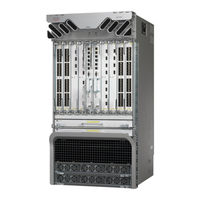
Cisco ASR 9001-S Overview And Reference Manual (170 pages)
ASR 9000 Series Aggregation Services Router
Brand:
Cisco
| Category:
Network Router
| Size: 17.11 MB
Table of Contents
Table of Contents
3
Preface
13
Related Documentation
13
Document Conventions
14
Obtaining Additional Information and Support
15
Chassis Physical Overview
18
Cisco ASR 9010 Router
18
Figure 1-1 Cisco ASR 9010 Router Chassis Components-Version 1 Power Trays
18
Figure 1-2 Cisco ASR 9010 Router Chassis Components-Version 2 Power Trays
19
Cisco ASR 9006 Router
20
Figure 1-3 Cisco ASR 9006 Router Chassis Components-Version 1 Power Tray
20
Figure 1-4 Cisco ASR 9006 Router Chassis Components-Version 2 Power Tray
20
Cisco ASR 9904 Router
21
Cisco ASR 9922 Router
21
Figure 1-6 Cisco ASR 9922 Router Chassis Components
22
Cisco ASR 9912 Router
23
Figure 1-7 Cisco ASR 9912 Router Chassis Components
23
Field Replaceable Units
24
Overview and Physical Description
18
Rack-Mounting Considerations
25
Figure 1-9 Cisco ASR 9006 Router Chassis Footprint Dimensions—Top down View
27
Figure 1-10 Cisco ASR 9904 Router Chassis Footprint Dimensions-Top down View
28
Figure 1-11 Cisco ASR 9922 Router Chassis Footprint Dimensions—Top down View
29
Chassis Slots
30
Fiber and Interface Cable Management
32
Figure 1-13 Cable Management Tray
32
Figure 1-14 Fiber/Cable Routing in the Cisco ASR 9010 Router
33
Figure 1-15 Routing of DC Power Tray Source Cables
33
Routing of DC Power Tray Source Cables
33
Figure 1-16 Cisco ASR 9010 Router Router Slot ID Numbering-Version 1 Power Trays
34
Slot Numbering and Marking
34
Figure 1-18 Cisco ASR 9006 Router Slot ID Numbering-Version 1 Power Tray
36
Figure 1-19 Cisco ASR 9006 Router Slot ID Numbering-Version 2 Power Tray
36
Figure 1-20 Cisco ASR 9904 Router Slot ID Numbering-Version 2 Power Tray
37
Figure 1-21 Cisco ASR 9922 Router Components and Slot Numbering
38
Figure 1-22 Cisco ASR 9912 Router Components and Slot Numbering
39
Power Module Hardware and Software Identification
39
Route Switch Processor and Route Processor Cards
40
RSP Front Panel and Access Ports
40
Table 1-1 Power Module Hardware and Software Ids
40
Figure 1-23 RSP Card Front Panel
41
Figure 1-24 RSP-440 Card Front Panel
42
RP Front Panel and Access Ports
43
Figure 1-25 RP Card Front Panel
44
Management Features
45
Alarm Connector
45
Figure 1-26 RP Card
45
Serviceability
46
RSP and RP Card Ejector Levers
46
Fabric Controller Card
46
Figure 1-27 FC Card
47
Figure 1-28 FC Card Front Panel
47
Ethernet Line Cards
48
FC Card Ejector Levers
48
Line Card Ejector Levers
49
Line Card Front Panel and Access Ports
49
Line Card Serviceability
49
Power System
49
AC and DC Power Modules
50
Figure 1-30 Front System View of Power Trays-Cisco ASR 9010 Router with Version 2 Power Trays
51
Figure 1-31 Front System View of Power Tray-Cisco ASR 9904 Router with Version 2 Power Tray
51
Cooling System
52
Figure 1-32 Front System View of Power Trays -Cisco ASR 9922 Router with Version 2 Power Trays
52
Cooling Path
53
Fan Trays
53
Management and Configuration
53
Figure 2-34 Modular Line Card
55
Router Operation
55
Chapter 2 Functional Description
56
Figure 2-3 Major System Components and Interconnections in the Cisco ASR 9000 Series Routers
57
Route Switch Processor Card
59
Figure 2-5 Major System Components and Interconnections in the Cisco ASR 9922 Series Router
59
Figure 2-7 RSP-440 Card Front Panel
61
Route Processor Card
62
Figure 2-8 RP Card Front Panel Connectors and Indicators
62
Front Panel Connectors
63
Management LAN Ports
63
Console Port
63
Auxiliary Port
63
Alarm out
63
Synchronization Ports
63
RP USB Port
64
Front Panel Indicators
64
LED Matrix Display
66
LED Matrix Boot Stage and Runtime Display
66
LED Matrix CAN Bus Controller Error Display
68
Functional Description
68
Switch Fabric
68
Figure 2-9 Switch Fabric Interconnections
69
Unicast Traffic
70
Multicast Traffic
70
Route Processor Functions
71
Processor-To-Processor Communication
72
Route Processor/Fabric Interconnect
72
Figure 2-12 RP Component Interconnections
72
Figure 2-13 FC Component Interconnections
72
Push Buttons
68
Fabric Controller Card
73
Figure 2-14 FC Card
74
Figure 2-15 FC Card Front Panel
74
FC Card Front Panel Indicator
75
Ethernet Line Cards
75
Functional Description
76
Table 2-7 Ethernet Line Cards Available for the Cisco ASR 9000 Series Routers
76
Figure 2-16 General Line Card Data Plane Block Diagram
77
40-Port Gigabit Ethernet (40X1Ge) Line Card
78
8-Port 10-Gigabit Ethernet (8X10Ge) 2:1 Oversubscribed Line Card
80
Figure 2-19 8-Port 10-Gigabit Ethernet (8X10Ge) 2:1 Oversubscribed Line Card Block Diagram
80
Figure 2-20 8-Port 10-Gigabit Ethernet (8X10Ge) 2:1 Oversubscribed Line Card Front Panel
81
4-Port 10-Gigabit Ethernet (4X10Ge) Line Card
82
Figure 2-22 4-Port 10-Gigabit Ethernet (4X10Ge) Line Card Front Panel
83
8-Port 10-Gigabit Ethernet (8X10Ge) 80-Gbps Line Rate Card
84
Figure 2-23 8-Port 10-Gigabit Ethernet (8X10Ge) 80-Gbps Line Rate Card Block Diagram
84
Figure 2-24 8-Port 10-Gigabit Ethernet (8X10Ge) 80-Gbps Line Rate Card Front Panel
85
Card
86
Figure 2-25 2-Port 10-Gigabit Ethernet + 20-Port Gigabit Ethernet (2X10Ge + 20X1Ge) Combination Line Card Block
86
Figure 2-26 2-Port 10-Gigabit Ethernet + 20-Port 1-Gigabit Ethernet (2X10Ge + 20X1Ge) Combination Line Card Front Panel
87
16-Port 10-Gigabit Ethernet (16X10Ge) Oversubscribed Line Card
88
Figure 2-28 16-Port 10-Gigabit Ethernet (16X10Ge) Oversubscribed Line Card Front Panel
89
24-Port 10-Gigabit Ethernet Line Card
90
Figure 2-30 24-Port 10-Gigabit Ethernet (24X10Ge) Line Card Front Panel
91
36-Port 10-Gigabit Ethernet Line Card
92
Figure 2-31 36-Port 10-Gigabit Ethernet (36X10Ge) Line Card Front Panel
93
2-Port 100-Gigabit Ethernet Line Card
94
Figure 2-32 2-Port 100-Gigabit Ethernet (2X100Ge) Line Card Front Panel
95
1-Port 100-Gigabit Ethernet Line Card
96
Figure 2-33 1-Port 100-Gigabit Ethernet (1X100Ge) Line Card Front Panel
97
Modular Line Cards
98
20-Port Gigabit Ethernet Modular Port Adapter
98
8-Port 10-Gigabit Ethernet Modular Port Adapter
99
4-Port 10-Gigabit Ethernet Modular Port Adapter
100
Figure 2-36 8-Port 10-Gigabit Ethernet MPA
100
2-Port 10-Gigabit Ethernet Modular Port Adapter
101
Figure 2-37 4-Port 10-Gigabit Ethernet MPA
101
2-Port 40-Gigabit Ethernet Modular Port Adapter
102
Figure 2-38 2-Port 10-Gigabit Ethernet MPA
102
1-Port 40-Gigabit Ethernet Modular Port Adapter
103
Figure 2-39 2-Port 40-Gigabit Ethernet MPA
103
Power System Functional Description
104
Figure 2-41 Cisco ASR 9010 Router AC Power System Block Diagram-Version 1 Power System
105
Figure 2-42 Cisco ASR 9010 Router AC Power System Block Diagram-Version 2 Power System
106
Figure 2-43 Cisco ASR 9010 Router DC Power System Block Diagram-Version 1 Power System
107
Figure 2-44 Cisco ASR 9010 Router DC Power System Block Diagram-Version 2 Power System
108
Figure 2-45 Cisco ASR 9006 Router AC Power System Block Diagram-Version 1 Power System
109
Figure 2-46 Cisco ASR 9006 Router AC Power System Block Diagram-Version 2 Power System
110
Figure 2-47 Cisco ASR 9006 Router DC Power System Block Diagram-Version 1 Power System
111
Figure 2-48 Cisco ASR 9006 Router DC Power System Block Diagram-Version 2 Power System
112
Figure 2-49 Cisco ASR 9904 Router AC Power System Block Diagram-Version 2 Power System
113
Figure 2-50 Cisco ASR 9904 Router DC Power System Block Diagram-Version 2 Power System
114
Figure 2-51 Cisco ASR 9922 Router AC Power System Block Diagram-Version 2 Power System
115
Figure 2-52 Cisco ASR 9922 Router DC Power System Block Diagram-Version 2 Power System
116
Figure 2-53 Version 1 Power Module
117
Figure 2-54 Version 2 Power Module
117
Figure 2-55 Version 1 Power Module Status Indicators
118
Power Module Status Indicators
118
Power Modules
117
Figure 2-56 Version 2 Power Module Status Indicators
119
System Power Redundancy
119
AC Power Trays
120
Figure 2-57 Version 1 AC Power Tray Rear Panel
120
Figure 2-58 Version 2 AC Power Tray Rear Panel
120
AC Input Voltage Range
121
AC Tray Power Switch
121
DC Output Levels
121
AC System Operation
122
Power up
122
Power down
122
DC Power Trays
122
DC Tray Power Switch
122
DC Power Tray Read Panel
122
DC Power Tray Power Feed Indicator
123
Figure 2-60 DC Power Tray Rear Panel
123
Figure 2-61 DC Power Tray Rear Panel - Cisco ASR 9006 Router and Cisco ASR 9904 Router with Version 2 Power System
123
DC System Operation
124
Power up
124
Power down
125
Cooling System Functional Description
125
Cooling Path
126
Figure 2-64 Cisco ASR 9010 Router Chassis Cooling Path-Side View
126
Line Cards
128
Fan Trays
130
Cisco ASR 9010 Router Fan Trays
130
Cisco ASR 9006 Router Fan Trays
130
Cisco ASR 9904 Router Fan Tray
131
Figure 2-70 Cisco ASR 9006 Router Fan Tray
131
Cisco ASR 9922 Router and Cisco ASR 9912 Router Fan Trays
132
Status Indicators
133
Fan Tray Servicing
133
Slot Fillers
134
Chassis Air Filter
134
Figure 2-73 Cisco ASR 9010 Router Chassis Air Filter
134
Figure 2-75 Cisco ASR 9904 Router Air Filter
136
Figure 2-76 ASR 9922 Router Chassis Air Filters
137
Figure 2-77 Cisco ASR 9912 Router Chassis Air Filters
138
Figure 2-78 Cisco ASR 9922 Router Chassis Center Air Filter
139
Speed Control
140
Temperature Sensing and Monitoring
140
Servicing
141
System Shutdown
141
System Management and Configuration
141
Cisco IOS XR Software
141
System Management Interfaces
141
Command-Line Interface
142
Craft Works Interface
142
Xml
142
Snmp
142
SNMP Agent
142
Mibs
143
Online Diagnostics
143
Chapter 3 High Availability and Redundant Operation
145
Features Overview
145
High Availability Router Operations
145
Stateful Switchover
145
Fabric Switchover
146
Active/Standby Status Interpretation
146
Non-Stop Forwarding
146
Nonstop Routing
146
Graceful Restart
146
Process Restartability
147
Fault Detection and Management
147
Power Supply Redundancy
147
AC Power Redundancy
148
Figure 3-1 AC System Power Redundancy for the Cisco ASR 9010 Router-Version
148
Figure 3-2 AC System Power Redundancy for the Cisco ASR 9010 Router-Version
148
Figure 3-3 AC System Power Redundancy for the Cisco ASR 9006 Router-Version
148
Figure 3-4 AC System Power Redundancy for the Cisco ASR 9904 Router-Version
149
Figure 3-5 AC System Power Redundancy for the Cisco ASR 9922 Router-Version
149
DC Power Redundancy
150
Figure 3-9 DC System Power Redundancy for the Cisco ASR 9006 Router Version-2
151
Figure 3-10 DC System Power Redundancy for the Cisco ASR 9904 Router-Version
151
Detection and Reporting of Power Problems
152
Cooling System Redundancy
152
Cooling Failure Alarm
153
Appendix
155
Technical Specifications
155
Table A-1 Cisco ASR 9010 Router Physical Specifications
155
Table A-2 Cisco ASR 9006 Router Physical Specifications
155
Table A-3 Cisco ASR 9904 Router Physical Specifications
155
Table
156
Appendix A Technical Specification
156
Table
157
Cisco ASR 9922 Router Physical Specifications
157
Table
158
Cisco ASR 9912 Router Physical Specifications
158
Cisco ASR 9000 Series Environmental Specifications
158
Cisco ASR 9006 Router AC Electrical Specifications
160
Table
161
Cisco ASR 9904 Router AC Electrical Specifications
161
Cisco ASR 9922 Router AC Electrical Specifications
161
Table
162
Cisco ASR 9912 Router AC Electrical Specifications
162
Cisco ASR 9010 Router DC Electrical Specifications
163
Table
164
Cisco ASR 9006 Router DC Electrical Specifications
164
Cisco ASR 9904 Router DC Electrical Specifications
164
Cisco ASR 9922 Router DC Electrical Specifications
164
Table
165
Cisco ASR 9912 Router DC Electrical Specifications
165
Table
166
AC Input Voltage Range
166
DC Input Voltage Range
166
DC Output Levels for Version 1 Power System
166
Table
167
DC Output Levels for Version 2 Power System
167
RSP/RP Port Specifications
167
Table
168
Card and Fan Tray Power Consumption Specifications
168
Advertisement
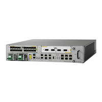
Cisco ASR 9001-S Hardware Installation Manual (160 pages)
Brand:
Cisco
| Category:
Network Router
| Size: 6.86 MB
Table of Contents
Table of Contents
3
Document Organization
10
Documentation Conventions
11
Obtaining Documentation and Submitting a Service Request
12
Preparing for Installation
13
Safety Guidelines
14
General Safety Guidelines
15
Energy Hazard
16
Lifting Guidelines
17
Site Wiring Guidelines
19
Chassis Air Flow Guidelines
20
Rack-Mounting and Air Flow Clearance Guidelines
21
Telco 2-Post Rack
22
Open 4-Post Rack
23
Enclosed Rack with Perforated Sides
24
Temperature and Humidity Guidelines
25
AC Powered Routers
26
AC Power Cord Illustrations
28
DC Powered Router
31
NEBS Supplemental Unit Bonding and Grounding Guidelines
34
Cisco ASR 9001 Router Port Connection Guidelines
35
Console Port and Auxiliary Port Connection Guidelines
37
Console Port Signals
38
Auxiliary Port Signals
38
Management LAN Ports Connection Guidelines
39
Management LAN Port LED Indicators
40
Management LAN RJ-45 Cabling
40
Sync Ports Connection Guidelines
41
SYNC Port LED Indicators
42
RP External USB Port
43
Unpacking and Installing the Chassis
45
Pre-Installation Considerations and Requirements
45
Unpacking the Cisco ASR 9001 Router
46
Positioning the Router
48
Installing the Cisco ASR 9001 Chassis
48
Before You Begin
48
Rack-Mounting the Chassis
48
Verifying Rack Dimensions
49
Installing the Chassis in a Two-Post Rack
49
Installing the Chassis in a Four-Post Rack
51
Supplemental Bonding and Grounding Connections
54
Installing the Optional Air Plenum Kit
55
Air Plenum Kit Contents
55
Supported Rack Types and Adapter Plates
56
Installing the Air Plenum Kit
56
Installing the Air Plenum Kit in a 19-Inch Rack
57
Installing the Air Plenum Kit in an ETSI Two-Post to Four-Post Rack
63
Installing Modules and Cables in the Chassis
69
Fixed 4X10-Gigabit Ethernet Ports
69
Modular Port Adapters
70
20-Port Gigabit Ethernet Modular Port Adapter
71
4-Port 10 Gigabit Ethernet Modular Port Adapter
72
2-Port 10 Gigabit Ethernet Modular Port Adapter
73
2-Port 40 Gigabit Ethernet Modular Port Adapter
75
1-Port 40 Gigabit Ethernet Modular Port Adapter
77
Installing and Removing Modular Port Adapters
79
Handling Modular Port Adapters (Mpas)
79
Online Insertion and Removal
80
Modular Port Adapter (MPA) Installation and Removal
81
Optical Device Installation and Removal
81
Cleaning Optical Devices
82
Checking the Installation
82
Verifying the Installation
82
Using Show Commands to Verify Modular Port Adapter (MPA) Status
83
Using Show Commands to Display Modular Port Adapter (MPA) Information
83
Using the Ping Command to Verify Network Connectivity
84
Installing and Removing SFP and XFP Modules
85
Cable Management
85
Cable Management Tray
85
Installing a Cable Management Tray
86
Removing a Cable-Management Tray
86
Cable Management Bracket
87
Installing a Cable Management Bracket
88
Removing a Cable-Management Bracket
88
Connecting Route Processor Cables
89
Connecting to the RP Console Port
91
Connecting to the RP Auxiliary Port
91
Connecting to the RP Ethernet Management Ports
92
Connecting Power to the Router
92
Connecting Power to an AC-Powered Router
92
Connecting Power to a DC-Powered Router
94
Powering on the Router
95
Troubleshooting the Installation
97
Troubleshooting Overview
97
Troubleshooting Using a Subsystem Approach
98
Normal Router Startup Sequence
98
Identifying Startup Issues
98
Troubleshooting the Power Subsystem
99
Troubleshooting the AC-Input Power Subsystem
99
Troubleshooting the DC-Input Power Subsystem
101
Troubleshooting a DC Power Module
101
Additional Power Subsystem Troubleshooting Information
102
Hardware and Software Identification
102
Obtaining Temperature and Environmental Information
102
Troubleshooting the Power Distribution System
106
Troubleshooting the Route Processor Subsystem
107
Route Processor Overview
107
RP Front Panel Indicators
108
Ethernet Ports and Status Leds
110
Auxiliary and Console Ports
110
Monitoring Critical, Major, and Minor Alarm Status
110
Troubleshooting the Line Card
111
Initial Boot Process
111
Status Leds
111
Configuring and Troubleshooting Line Card Interfaces
112
Configuration Parameters
112
Line Card Interface Address
113
Using Configuration Commands
113
Basic Line Card Configuration
113
Verifying the Transceiver Modules
115
Advanced Line Card Troubleshooting
116
Troubleshooting the Cooling Subsystem
116
Fan Tray Operation
117
Power Module Fans
117
Over-Temperature Conditions
117
Isolating Cooling Subsystem Problems
118
Replacing Cisco ASR 9001 Router Components
121
Prerequisites and Preparation
121
Field Replaceable Units
121
Online Insertion and Removal
122
Powering off the Router
122
Removing and Replacing the Fan Tray
123
Removing and Replacing a Fan Tray
124
Removing and Replacing the Air Filter
125
Removing and Replacing AC or DC Power System Components
127
Power Module Replacement Guidelines
127
Removing and Replacing an AC or DC Power Module
127
Removing an AC or DC Power Module
127
Installing an AC or DC Power Module
128
Removing a Chassis from the Equipment Rack
128
Installing a Replacement Chassis in the Equipment Rack
129
Packing a Chassis for Shipment
129
Appendix A Technical Specifications
131
Physical Specifications
132
Environmental Specifications
132
AC Electrical Specifications
133
DC Electrical Specifications
134
AC Input Voltage Range
134
DC Input Voltage Range
135
Power System DC Output Levels
135
RP Port Specifications
135
Power Consumption Specifications
136
Fast Ethernet and Gigabit Ethernet SFP Modules
137
10-Gigabit Ethernet SFP+ Transceiver Modules
138
SFP+ Transceiver Modules
143
DWDM SFP+ Transceiver Modules
145
DWDM XFP Transceiver Modules
145
CWDM SFP Transceiver Modules
148
10GBASE CWDM SFP+ 40Km Transceiver Modules
148
DWDM SFP Transceiver Modules
149
DWDM SFP+ Transceiver Modules
153
Gigabit Ethernet XFP and 40-Gigabit QSFP Modules
155
Site Log
159
Cisco ASR 9001-S Hardware Installation Manual (158 pages)
Brand:
Cisco
| Category:
Network Router
| Size: 10.64 MB
Table of Contents
Table of Contents
3
Chapter 1
9
Overview
9
Safety Guidelines
11
Compliance and Safety Information
12
Lifting Guidelines
13
Site Requirement Guidelines
14
Site Wiring Guidelines
16
Chassis Air Flow Guidelines
17
Rack-Mounting and Air Flow Clearance Guidelines
19
Telco 2-Post Rack
20
Open 4-Post Rack
22
Air Flow Guidelines for Enclosed Rack Installation
23
Temperature and Humidity Guidelines
24
Power Connection Guidelines
25
DC Powered Router
38
NEBS Supplemental Unit Bonding and Grounding Guidelines
42
Port Connection Guidelines
43
Console Port and Auxiliary Port Connection Guidelines
46
Auxiliary Port Signals
47
Management LAN Port LED Indicators
48
Sync Ports Connection Guidelines
49
RP External USB Port
50
Chapter 2
53
Pre-Installation Considerations and Requirements
53
Unpacking the Router
54
Positioning the Router
56
Installing the Chassis in a Two-Post Rack
57
Installing the Chassis in a Four-Post Rack
60
Installing the Cisco ASR 9001 Chassis
64
Rack-Mounting the Chassis
65
Installing the Chassis in a Four-Post Rack
67
Supplemental Bonding and Grounding Connections
68
Installing the Optional Air Plenum Kit
70
Installing the Air Plenum Kit
71
Installing the Air Plenum Kit in an ETSI Two-Post to Four-Post Rack
75
Chapter 3
81
Cisco ASR 9901 Router Fixed Ports
81
Cisco ASR 9001 Router Fixed Ports and Modular Port Adapters
82
Modular Port Adapters
83
Port 10 Gigabit Ethernet Modular Port Adapter
84
Port 10 Gigabit Ethernet Modular Port Adapter
85
Port 40 Gigabit Ethernet Modular Port Adapter
86
Installing and Removing Modular Port Adapters
87
Handling Modular Port Adapters (Mpas)
88
Modular Port Adapter (MPA) Installation and Removal
89
Optical Device Installation and Removal
90
Installing and Removing Transceiver Modules
93
Installing a Cable Management Bracket
94
Removing a Cable-Management Bracket
95
Cable Management Bracket—Cisco ASR 9001
96
Removing a Cable-Management Bracket
97
Cable Management Tray—Cisco ASR 9001
98
Removing a Cable-Management Tray
99
Connecting Route Processor Cables
100
Connecting to the RP Auxiliary Port
101
Connecting Power to the Router
102
Connecting Power to a DC-Powered Router
104
Powering on the Router
106
Chapter 4
109
Troubleshooting Overview
109
Normal Router Startup Sequence
110
Troubleshooting the Power Subsystem
111
Troubleshooting the DC-Input Power Subsystem
115
Additional Power Subsystem Troubleshooting Information
118
Hardware and Software Identification
119
Troubleshooting the Power Distribution System
123
Route Processor Overview
124
RP Front Panel Indicators
125
LED Matrix Display
127
Ethernet Ports and Status Leds
128
Auxiliary and Console Ports
129
Troubleshooting the Line Card
130
Configuring and Troubleshooting Line Card Interfaces
131
Verifying the Transceiver Modules
133
Advanced Line Card Troubleshooting
134
Troubleshooting the Cooling Subsystem
135
Power Module Fans
136
Isolating Cooling Subsystem Problems
137
Chapter 5
139
Prerequisites and Preparation
139
Online Insertion and Removal
140
Removing and Replacing the Fan Tray
141
Removing and Replacing a Fan Tray
142
Removing and Replacing the Air Filter
143
Removing and Replacing AC or DC Power System Components
145
Installing an AC or DC Power Module
147
Installing a Replacement Chassis in the Equipment Rack
148
Physical Specifications
149
Environmental Specifications
150
AC Electrical Specifications
151
DC Electrical Specifications
152
AC Input Voltage Range
154
RP Port Specifications
155
Transceiver Modules
156
Site Log
157
Advertisement
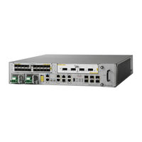
Cisco ASR 9001-S Hardware Installation Manual (114 pages)
Brand:
Cisco
| Category:
Network Router
| Size: 14.8 MB
Table of Contents
Table of Contents
3
Document Conventions
8
Document Organization
8
Obtaining Documentation and Submitting a Service Request
9
CHAPTER 1 Preparing for Installation
11
Safety Guidelines
12
General Safety Guidelines
12
Compliance and Safety Information
13
Laser Safety
13
Energy Hazard
13
Preventing Electrostatic Discharge Damage
14
Lifting Guidelines
14
Site Requirement Guidelines
15
Site Layout and Equipment Dimensions
15
Site Wiring Guidelines
17
Chassis Air Flow Guidelines
17
Rack-Mounting and Air Flow Clearance Guidelines
18
Telco 2-Post Rack
19
Enclosed Rack with Perforated Sides
20
Open 4-Post Rack
20
Air Flow Guidelines for Enclosed Rack Installation
21
Temperature and Humidity Guidelines
22
Power Connection Guidelines
22
AC Power Cord Illustrations
23
AC Powered Routers
23
DC Powered Router
27
NEBS Supplemental Unit Bonding and Grounding Guidelines
30
Cisco ASR 9001 Router Port Connection Guidelines
31
Console Port and Auxiliary Port Connection Guidelines
33
Console Port Signals
33
Auxiliary Port Signals
34
Management LAN Ports Connection Guidelines
34
Management LAN Port LED Indicators
35
Management LAN RJ-45 Cabling
35
Sync Ports Connection Guidelines
36
SYNC Port LED Indicators
36
RP External USB Port
37
C H a P T E R 1 Preparing for Installation Cisco ASR 9001 Router 1
38
CHAPTER 2 Unpacking and Installing the Chassis
39
Pre-Installation Considerations and Requirements
39
Installation Overview
39
Required Tools and Equipment
40
Unpacking the Cisco ASR 9001 Router
40
C H a P T E R 2 Unpacking and Installing the Chassis
41
Positioning the Router
41
Rack-Mounting the Router Chassis
42
Verifying Rack Dimensions
42
Installing the Chassis in a 2-Post Rack
42
Installing the Chassis in a 4-Post Rack
45
Supplemental Bonding and Grounding Connections
45
CHAPTER 3 Installing Modules and Cables in the Chassis3-1
47
Fixed 4X10-Gigabit Ethernet Ports
47
Modular Port Adapters
48
20-Port Gigabit Ethernet Modular Port Adapter
48
C H a P T E R 3 Installing Modules and Cables in the Chassis
49
4-Port 10 Gigabit Ethernet Modular Port Adapter
49
2-Port 10 Gigabit Ethernet Modular Port Adapter
50
Installing and Removing Modular Port Adapters
51
Handling Modular Port Adapters (Mpas)
52
Online Insertion and Removal
52
Modular Port Adapter (MPA) Installation and Removal
53
Optical Device Installation and Removal
54
Cleaning Optical Devices
54
Checking the Installation
54
Using Show Commands to Verify Modular Port Adapter (MPA) Status
54
Verifying the Installation
54
Using Show Commands to Display Modular Port Adapter (MPA) Information
56
Using the Ping Command to Verify Network Connectivity
56
Installing and Removing SFP Modules
57
Installing and Removing XFP Modules
57
Cable Management
58
Cable Management Tray
58
Installing a Cable Management Tray
58
Removing a Cable-Management Tray
59
Cable Management Bracket
60
Installing a Cable Management Bracket
60
Removing a Cable-Management Bracket
61
Connecting Route Processor Cables
62
Connecting to the RP Console Port
63
Connecting to the RP Auxiliary Port
63
Connecting to the RP Ethernet Management Ports
63
Connecting Power to the Router
64
Connecting Power to an AC-Powered Router
64
Connecting Power to a DC-Powered Router
66
Powering on the Router
67
Chapter 4 Troubleshooting the Installation
69
Troubleshooting Overview
69
Troubleshooting Using a Subsystem Approach
69
Normal Router Startup Sequence
70
Identifying Startup Issues
70
Troubleshooting the Power Subsystem
71
Troubleshooting the AC-Input Power Subsystem
71
Troubleshooting the DC-Input Power Subsystem
73
Troubleshooting a DC Power Module
73
Additional Power Subsystem Troubleshooting Information
74
Hardware and Software Identification
74
Obtaining Temperature and Environmental Information
74
Troubleshooting the Power Distribution System
76
Troubleshooting the Route Processor Subsystem
77
Route Processor Overview
77
RP Front Panel Indicators
78
Auxiliary and Console Ports
79
Ethernet Ports and Status Leds
79
Monitoring Critical, Major, and Minor Alarm Status
80
Troubleshooting the Line Card
80
Initial Boot Process
80
Status Leds
80
Configuring and Troubleshooting Line Card Interfaces
81
Configuration Parameters
81
Basic Line Card Configuration
82
Line Card Interface Address
82
Using Configuration Commands
82
Verifying the Transceiver Modules
83
Advanced Line Card Troubleshooting
85
Troubleshooting the Cooling Subsystem
86
Fan Tray Operation
86
Power Module Fans
86
Isolating Cooling Subsystem Problems
87
Over-Temperature Conditions
87
Prerequisites and Preparation
89
Field Replaceable Units
89
CHAPTER 5 Replacing Cisco Asr 9001 Router Components
89
Online Insertion and Removal
90
Powering off the Router
90
Removing and Replacing the Fan Tray
90
Removing and Replacing AC or DC Power System Components
91
Power Module Replacement Guidelines
92
Removing and Replacing an AC or DC Power Module
92
Removing an AC or DC Power Module
92
Installing an AC or DC Power Module
93
Removing a Chassis from the Equipment Rack
93
Installing a Replacement Chassis in the Equipment Rack
94
Packing a Chassis for Shipment
94
Appendix
95
Technical Specifications
95
Appendix
105
Site Log
105
I N D E X
107
Advertisement
Related Products
Cisco ASR 9000 Series
Cisco ASR 9000 Serie
Cisco ASR 900 Series
Cisco ASR 9001
Cisco ASR 9006
Cisco ASR 9000
Cisco ASR 9000v
Cisco ASR 901S Series
Cisco ASR 907
Cisco ASR 902U
Cisco Categories
Switch
IP Phone
Network Router
Wireless Access Point
Conference System
More Cisco Manuals
Login
Sign In
OR
Sign in with Facebook
Sign in with Google
Upload manual
Upload from disk
Upload from URL