Table of Contents
Advertisement
Advertisement
Table of Contents
Troubleshooting

Related Manuals for Cisco ASR 9901


Summary of Contents for Cisco ASR 9901
- Page 1 Cisco ASR 9901, ASR 9001, and ASR 9001-S Routers Hardware Installation Guide First Published: 2013-08-25 Last Modified: 2018-03-08 Americas Headquarters Cisco Systems, Inc. 170 West Tasman Drive San Jose, CA 95134-1706 http://www.cisco.com Tel: 408 526-4000 800 553-NETS (6387) Fax: 408 527-0883...
- Page 2 Cisco and the Cisco logo are trademarks or registered trademarks of Cisco and/or its affiliates in the U.S. and other countries. To view a list of Cisco trademarks, go to this URL: https://www.cisco.com/go/trademarks. Third-party trademarks mentioned are the property of their respective owners. The use of the word partner does not imply a partnership relationship between Cisco and any other company.
-
Page 3: Table Of Contents
Power Connection Guidelines AC Powered Routers DC Powered Router NEBS Supplemental Unit Bonding and Grounding Guidelines Port Connection Guidelines Console Port and Auxiliary Port Connection Guidelines Console Port Signals Cisco ASR 9901, ASR 9001, and ASR 9001-S Routers Hardware Installation Guide... - Page 4 C H A P T E R 3 Installing Modules and Cables in the Chassis Cisco ASR 9901 Router Fixed Ports Cisco ASR 9001 Router Fixed Ports and Modular Port Adapters Fixed 4x10-Gigabit Ethernet Ports Cisco ASR 9901, ASR 9001, and ASR 9001-S Routers Hardware Installation Guide...
- Page 5 Connecting Power to a DC-Powered Router Powering on the Router C H A P T E R 4 Troubleshooting the Installation Troubleshooting Overview Troubleshooting Using a Subsystem Approach Cisco ASR 9901, ASR 9001, and ASR 9001-S Routers Hardware Installation Guide...
- Page 6 Troubleshooting the Cooling Subsystem Fan Tray Operation Power Module Fans Over-temperature Conditions Isolating Cooling Subsystem Problems C H A P T E R 5 Replacing Router Components Prerequisites and Preparation Cisco ASR 9901, ASR 9001, and ASR 9001-S Routers Hardware Installation Guide...
- Page 7 DC Input Voltage Range Power System DC Output Levels RP Port Specifications Power Consumption Specifications Transceiver Modules A P P E N D I X B Site Log Site Log Cisco ASR 9901, ASR 9001, and ASR 9001-S Routers Hardware Installation Guide...
- Page 8 Contents Cisco ASR 9901, ASR 9001, and ASR 9001-S Routers Hardware Installation Guide viii...
-
Page 9: Overview
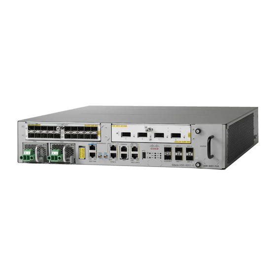
Port Connection Guidelines, on page 35 Overview Cisco ASR 9901 Router The Cisco ASR 9901 Router is a compact high-capacity provider edge (PE) router that delivers 456 Gbps of non-blocking, full-duplex fabric capacity in a two-rack-unit (2RU) form factor. Note The Cisco ASR 9901 Router supports Cisco IOS XR 64-bit releases only. - Page 10 Figure 1: Front Panel of the Cisco ASR 9901 Router Cisco ASR 9001 Router The Cisco ASR 9001 Router is a compact high-capacity provider edge (PE) router that delivers 120 Gbps of non-blocking, full-duplex fabric capacity in a two-rack-unit (2RU) form factor. Similar to other routers in the...
-
Page 11: Safety Guidelines
Figure 3: Front Panel of the Cisco ASR 9001-S Router In order to achieve the full bandwidth of 120 Gbps and to enable the disabled ports, a Cisco license can be obtained. Once the license is obtained and installed, the Cisco ASR 9001-S Router must be reloaded to bring up the full 120 Gbps capacity. -
Page 12: Compliance And Safety Information
Statement 1051 Energy Hazard The Cisco ASR 9901 and Cisco ASR 9001 Router can be configured for a DC power source. Do not touch terminals while they are live. Observe this warning to prevent injury. -
Page 13: Lifting Guidelines
ASR 9001 Router Lifting Guidelines A fully-configured Cisco ASR 9901 can weigh as much as 55.97 pounds (25.4 kg). A fully-configured Cisco ASR 9001 Router can weigh as much as 37.91 pounds (17.2 kg). These systems are not intended to be moved frequently. -
Page 14: Site Requirement Guidelines
• To mount the router between two posts or rails, the usable aperture (the width between the inner edges of the two mounting flanges) must be at least 17.7 inches (45 cm) for the Cisco ASR 9001 Router and at least 17.75 inches (45.09 cm) for the Cisco ASR 9901 Router. - Page 15 Site Layout and Equipment Dimensions Figure 5: Cisco ASR 9901 Router Chassis Footprint and Dimensions Top View The following figure shows the top-down view chassis dimensions of the Cisco ASR 9001 Router. Cisco ASR 9901, ASR 9001, and ASR 9001-S Routers Hardware Installation Guide...
-
Page 16: Site Wiring Guidelines
Note To predict and remedy strong EMI, you may need to consult with radio frequency interference (RFI) experts. Cisco ASR 9901, ASR 9001, and ASR 9001-S Routers Hardware Installation Guide... -
Page 17: Chassis Air Flow Guidelines
Chassis Air Flow Guidelines Cisco ASR 9901 Router Cool air is circulated front-to-back through the Cisco ASR 9901 Router by three fan trays located in the rear of the router (see the following figure). The fan trays maintain acceptable operating temperatures for the internal components by drawing in cool air through the vents, and circulating the air through the chassis. - Page 18 Figure 7: Air Flow Path through the Cisco ASR 9901 Router Cisco ASR 9001 Router Cool air is circulated through the Cisco ASR 9001 Router by one fan tray located along the right side of the router (see the following figure).
-
Page 19: Rack-Mounting And Air Flow Clearance Guidelines
18.31 inches ± 0.06 inch (46.50 cm ± 0.15 cm). The following figure shows examples of typical 2-post, 4-post, and telco-type equipment racks. Cisco ASR 9901, ASR 9001, and ASR 9001-S Routers Hardware Installation Guide... -
Page 20: Telco 2-Post Rack
Cisco ASR 9901 Router The Cisco ASR 9901 Router can be installed in 19-inch or 23-inch (with extension adapter plates) telco-style racks. The chassis is supported by slide rails that are installed on the rear of the rack posts. Mounting brackets are installed on the sides of the chassis and are inserted along the slide rails. - Page 21 Note The mounting brackets on the Cisco ASR 9001 Router chassis have a pair of holes at the top and bottom of each bracket and three slots (elongated holes). If the Cisco ASR 9001 Router is to be mounted in a 2-post 19-inch rack, you must first use the holes to locate and position the brackets on the rack.
-
Page 22: Open 4-Post Rack
Two adjustable 4-post slide rails and two side-mounted guide brackets are provided for mounting the Cisco ASR 9901 Router in a 4-post rack. Two rear mounting brackets are provided for mounting the Cisco ASR 9001 Router in a 4-post rack. -
Page 23: Air Flow Guidelines For Enclosed Rack Installation
Air Flow Guidelines for Enclosed Rack Installation To install a Cisco ASR 9901 or Cisco ASR 9001 Router in an enclosed cabinet, the front and rear doors of the cabinet must be removed or be perforated with a minimum of 65% open area (70% for ETSI 800mm racks). -
Page 24: Temperature And Humidity Guidelines
Temperature and Humidity Guidelines Cisco ASR 9001 If you are mounting the Cisco ASR 9001 chassis in a 4-post enclosed cabinet, ensure that you have these clearances around the chassis: • Rear: Minimum of 3.15 inches (8.00 cm) of clearance •... -
Page 25: Power Connection Guidelines
National Electrical Code (NEC) as well as local codes. Caution Each Cisco ASR 9901 or Cisco ASR 9001 Router is powered by only one type of input: AC or DC. A hybrid (AC+DC) power configuration is not supported. - Page 26 14 ft (4.26 20A, 300 VAC/500 International IEC/EU, Ring Terminal CAB-HV-25A-SG-IN2 14 ft (4.26 20A, 300 VAC/500 source plug International IEC/EU CAB-HV-25A-SG-IN3 14 ft (4.26 20A, 300 VAC Cisco ASR 9901, ASR 9001, and ASR 9001-S Routers Hardware Installation Guide...
- Page 27 This section contains the AC power cord illustrations, as described in the above table. Note that an AC power cord may be used with several power supplies. Figure 14: CAB-AC-16A-SG-AR Power Cord Figure 15: CAB-AC-16A-SG-AZ Power Cord Figure 16: CAB-AC-16A-SG-BR Power Cord Cisco ASR 9901, ASR 9001, and ASR 9001-S Routers Hardware Installation Guide...
- Page 28 Preparing for Installation AC Powered Routers Figure 17: CAB-AC-16A-SG-CH Power Cord Figure 18: CAB-AC-16A-SG-EU Power Cord Figure 19: CAB-AC-16A-SG-IND Power Cord Cisco ASR 9901, ASR 9001, and ASR 9001-S Routers Hardware Installation Guide...
- Page 29 Preparing for Installation AC Powered Routers Figure 20: CAB-AC-16A-SG-IN Power Cord Figure 21: CAB-AC-16A-SG-IS Power Cord Figure 22: CAB-AC-16A-SG-IT Power Cord Cisco ASR 9901, ASR 9001, and ASR 9001-S Routers Hardware Installation Guide...
- Page 30 Preparing for Installation AC Powered Routers Figure 23: CAB-AC-16A-SG-JPN Power Cord Figure 24: CAB-AC-16A-SG-SA Power Cord Figure 25: CAB-AC-16A-SG-SW Power Cord Cisco ASR 9901, ASR 9001, and ASR 9001-S Routers Hardware Installation Guide...
- Page 31 Preparing for Installation AC Powered Routers Figure 26: CAB-AC-16A-SG-UK Power Cord Figure 27: CAB-AC-20A-SG-US Power Cord Figure 28: CAB-AC-20A-SG-US1 Power Cord Cisco ASR 9901, ASR 9001, and ASR 9001-S Routers Hardware Installation Guide...
- Page 32 Preparing for Installation AC Powered Routers Figure 29: CAB-AC-20A-SG-US2 Power Cord Figure 30: CAB-AC-20A-SG-US3 Power Cord Figure 31: CAB-AC-20A-SG-US4 Power Cord Cisco ASR 9901, ASR 9001, and ASR 9001-S Routers Hardware Installation Guide...
- Page 33 Preparing for Installation AC Powered Routers Figure 32: CAB-AC-20A-SG-C20 Power Cord Figure 33: CAB-HV-25A-SG-US2 Power Cord Figure 34: CAB-HV-25A-SG-IN2 Power Cord Cisco ASR 9901, ASR 9001, and ASR 9001-S Routers Hardware Installation Guide...
- Page 34 AC Input Voltage Range, on page 146. The following table lists the AC-input power cord options, specifications, and Cisco product numbers for the Cisco ASR 9001 AC-input power supply modules. This table also references power cord illustrations. For more information on Cisco product numbers (PIDs) and their detailed description of power cords, refer to Dynamic Configuration Tool.
- Page 35 This section contains the AC power cord illustrations, as described in the above table. Note that an AC power cord may be used with several power supplies. Figure 36: AC Power Cord CAB-AC Figure 37: AC Power Cord CAB-L620P-C13-JPN Figure 38: AC Power Cord CAB-ACA Cisco ASR 9901, ASR 9001, and ASR 9001-S Routers Hardware Installation Guide...
- Page 36 Preparing for Installation AC Powered Routers Figure 39: AC Power Cord CAB-ACI Figure 40: AC Power Cord CAB-ACR Figure 41: AC Power Cord CAB-ACS Cisco ASR 9901, ASR 9001, and ASR 9001-S Routers Hardware Installation Guide...
- Page 37 Preparing for Installation AC Powered Routers Figure 42: AC Power Cord CAB-ACU Figure 43: AC Power Cord CAB-ACC Figure 44: AC Power Cord CAB-ACSA Cisco ASR 9901, ASR 9001, and ASR 9001-S Routers Hardware Installation Guide...
-
Page 38: Dc Powered Router
The length of the cables depends on your router location from the source power. Note DC power cables are not available from Cisco, but they are available from external commercial cable vendors. You must terminate DC power cables using terminal blocks. The terminal blocks are supplied along with the DC power supply modules from Cisco. - Page 39 Be sure uninsulated conductors are not accessible when cover is in place. Statement 1086 Warning Only trained and qualified personnel should be allowed to install, replace, or service this equipment. Statement 1030 Cisco ASR 9901, ASR 9001, and ASR 9001-S Routers Hardware Installation Guide...
- Page 40 Preparing for Installation DC Powered Router Figure 49: Cisco ASR 9901 DC Power Source Cabling Scheme for a Single DC Power Module Cisco ASR 9901, ASR 9001, and ASR 9001-S Routers Hardware Installation Guide...
- Page 41 DC Powered Router Figure 50: Cisco ASR 9001 DC Power Source Cabling Scheme for a Single DC Power Module The color coding of the source DC power cable leads depends on the color coding of the site DC power source.
-
Page 42: Nebs Supplemental Unit Bonding And Grounding Guidelines
AC power modules. The following figures show the NEBS grounding locations for the Cisco ASR 9901 Router and Cisco ASR 9001 Router. -
Page 43: Port Connection Guidelines
Preparing for Installation Port Connection Guidelines Figure 52: NEBS Bonding and Grounding Points on the Cisco ASR 9001 Router NEBS grounding point on side of chassis To ensure a satisfactory supplemental ground connection to the router, use these parts: • One grounding lug, which has two M6 bolt holes with 0.625- to 0.75-inch (15.86- to 19.05-mm) spacing between them, and a wire receptacle large enough to accept a six AWG or larger, multistrand copper wire. - Page 44 Service LAN and ToD External USB port ports 10MHz and 1PPS ports Eight discrete LED indicators SYNC (BITS/J.211) ports CLUSTER ports CONSOLE and AUX Fixed SFP+ ports ports Management LAN ports Cisco ASR 9901, ASR 9001, and ASR 9001-S Routers Hardware Installation Guide...
- Page 45 Port Connection Guidelines Note In Cisco ASR 9001-S Router, two 10 GE fixed SFP+ ports (SFP+2 and SFP+3) are disabled by default, and can be enabled by a license upgrade. The following table lists the Cisco ASR 9901 and Cisco ASR 9001 Router front panel ports description.
-
Page 46: Console Port And Auxiliary Port Connection Guidelines
Table 4: RP Console Port Signals Console Port Pin Signal Input/Output Description Output Request to Send — — (Not connected) Output Transmit data — Signal ground — Signal ground Cisco ASR 9901, ASR 9001, and ASR 9001-S Routers Hardware Installation Guide... -
Page 47: Auxiliary Port Signals
• Maximum transmission unit (MTU) is fixed at 1514 and cannot be configured. • Flow control is disabled and cannot be configured. • Input unicast packets with an unknown destination address are filtered and dropped. Cisco ASR 9901, ASR 9001, and ASR 9001-S Routers Hardware Installation Guide... -
Page 48: Management Lan Port Led Indicators
Figure 55: RP Management LAN Port LED Indicators Management LAN RJ-45 Cabling When connecting the RJ-45 port to a hub, repeater, or switch, use the straight-through cable pinout shown in the following figure. Cisco ASR 9901, ASR 9001, and ASR 9001-S Routers Hardware Installation Guide... -
Page 49: Sync Ports Connection Guidelines
SYNC Port LED Indicators The SYNC port connector has integral LED indicators (see the following figure). When lit, these LEDs indicate: Cisco ASR 9901, ASR 9001, and ASR 9001-S Routers Hardware Installation Guide... -
Page 50: Rp External Usb Port
RP External USB Port The Cisco ASR 9901 Router and Cisco ASR 9001 Router has an external USB Type A slot accessible on the front panel. The front panel USB slot accepts widely available USB thumb drives. The only restriction on devices you can plug into the front panel external USB slot is that they need to be USB 2.0 devices. - Page 51 Preparing for Installation RP External USB Port Note Do not connect a USB hub device to the front panel USB port. Cisco ASR 9901, ASR 9001, and ASR 9001-S Routers Hardware Installation Guide...
- Page 52 Preparing for Installation RP External USB Port Cisco ASR 9901, ASR 9001, and ASR 9001-S Routers Hardware Installation Guide...
-
Page 53: Pre-Installation Considerations And Requirements
Cisco ASR 9000 Series Aggregation Services Routers. Note A fully-equipped ASR 9901 router with 2 power modules and 3 fans can weigh as much as 55.97 pounds (25.4 kg); an empty chassis weighs 47.62 pounds (21.6 kg). A fully-equipped ASR 9001 router with two power modules can weigh as much as 37.91 pounds (17.2 kg);... -
Page 54: Unpacking The Router
Unpacking the Router Unpacking the Router Follow these steps to unpack the Cisco ASR 9901 Router or Cisco ASR 9001 Router from its shipping container (see the below figures). Figure 59: Unpacking the Cisco ASR 9901 Router from the Shipping Container... - Page 55 Remove the packaging material (see the below figure). a) Remove the foam packaging material from the top of the router. b) Remove the cardboard cap from the side of the router. Cisco ASR 9901, ASR 9001, and ASR 9001-S Routers Hardware Installation Guide...
-
Page 56: Positioning The Router
Measure the space between the inner edges of the left front and right front mounting flanges on the equipment rack. • Cisco ASR 9901—The space must be at least 17.75 inches (45.085 cm) to accommodate the width of the chassis with the mounting brackets and slide rails, and fits between the mounting posts on the rack. -
Page 57: Installing The Chassis In A Two-Post Rack
• One of the following rack-mounting kits (provided by Cisco): • Cisco PID ASR-9901-2P-KIT for mounting the chassis in a 19-inch or 23-inch two-post rack. • Cisco PID ASR-9901-4P-KIT for mounting the chassis in a 19-inch or 23-inch four-post rack. - Page 58 M5 pan head screws per side. The recommended maximum torque is 31 in.-lb (3.5 N-m). Step 3 Use two persons to lift the chassis into the rack holding the top and bottom of the chassis. Cisco ASR 9901, ASR 9001, and ASR 9001-S Routers Hardware Installation Guide...
- Page 59 Hold the chassis in position against the mounting rails while the second person finger-tightens four screws to the rack rails on each side of the chassis (see the figure below). Figure 62: 19-Inch Two-Post Rack Cisco ASR 9901, ASR 9001, and ASR 9001-S Routers Hardware Installation Guide...
-
Page 60: Installing The Chassis In A Four-Post Rack
Step 1 Attach the mounting brackets to the sides of the chassis using twelve M4 flat-head screws per side. The recommended maximum torque is 15 in.-lb (1.7 N-m). Cisco ASR 9901, ASR 9001, and ASR 9001-S Routers Hardware Installation Guide... - Page 61 M5 pan head screws in the center holes of the front bracket and four M5 pan head screws for the rear bracket. The recommended maximum torque is 31 in.-lb (3.5 N-m). Cisco ASR 9901, ASR 9001, and ASR 9001-S Routers Hardware Installation Guide...
- Page 62 Hold the chassis in position against the mounting rails while the second person finger-tightens four screws to the rack rails on each side of the chassis (see the figure below). Cisco ASR 9901, ASR 9001, and ASR 9001-S Routers Hardware Installation Guide...
- Page 63 Unpacking and Installing the Chassis Installing the Chassis in a Four-Post Rack Figure 65: 19-Inch Four-Post Rack Cisco ASR 9901, ASR 9001, and ASR 9001-S Routers Hardware Installation Guide...
-
Page 64: Installing The Cisco Asr 9001 Chassis
Fully tighten all the screws to secure the chassis to the rack rails. Installing the Cisco ASR 9001 Chassis This chapter describes how to install a Cisco ASR 9001 chassis in a rack. It includes the following sections: Before you Begin Before you install the chassis, make sure that you have following tools and equipment: •... -
Page 65: Rack-Mounting The Chassis
(also called rails ) in the rack. Three screws should be installed on each side of the chassis. • One of the following rack-mounting kits (provided by Cisco): • Cisco PID ASR-9001-2P-KIT= for mounting the chassis in a 19-inch two-post rack. • Cisco PID ASR-9001-2PL-KIT= for mounting the chassis in a 23-inch two-post rack. - Page 66 (see the figure below). Step 6 Fully tighten all the screws on the chassis mounting flanges and bracket flanges (each side) to secure the chassis to the rack rails. Cisco ASR 9901, ASR 9001, and ASR 9001-S Routers Hardware Installation Guide...
-
Page 67: Installing The Chassis In A Four-Post Rack
Step 3 Fully tighten both screws to the chassis on each side to secure the chassis to the rear posts. Cisco ASR 9901, ASR 9001, and ASR 9001-S Routers Hardware Installation Guide... -
Page 68: Supplemental Bonding And Grounding Connections
Unpacking and Installing the Chassis Supplemental Bonding and Grounding Connections What to do next Figure 69: Installing the Cisco ASR 9001 Router Chassis in a Four-Post Rack Three screws on each side (minimum two) to Two rear mounting brackets on each side to attach attach the chassis to the rack. - Page 69 Unpacking and Installing the Chassis Supplemental Bonding and Grounding Connections Figure 70: NEBS Bonding and Grounding for the Cisco ASR 9901 Router Figure 71: NEBS Bonding and Grounding for the Cisco ASR 9001 Router Step 2 Tighten the grounding screws securely to the receptacles.
-
Page 70: Installing The Optional Air Plenum Kit
• One grounding bracket • Two grounding lugs with four M4 screws (two screws per grounding lug) • Two 10-32 UNC screws and two M4 screws (for attaching the grounding bracket the Cisco ASR 9001 chassis) Supported Rack Types and Adapter Plates The following table lists the racks that support the optional air plenum kit and adapter plates. -
Page 71: Installing The Air Plenum Kit
Installing the Air Plenum Kit The air plenum kit is mounted in the rack before the Cisco ASR 9001 Router is installed. The steps for mounting the air plenum kit in the rack are different, depending on the whether the kit is pre-assembled before mounting it in the rack or assembled after the plenum base is mounted in the rack. - Page 72 Step 4 Attach the left and right air baffles to the plenum base using the Cisco supplied M5x10mm screws (four for each air baffle). The keyholes on each side of the plenum base will help to guide the air baffles into position (see Attaching the Air Baffles to the Plenum Base figure).
- Page 73 Figure 73: Attaching the Rear Adapter Plates (Four-Post Rack) Step 8 Place the Cisco ASR 9001 Router on a flat and stable surface. Attach the rear grounding bracket (see the figure below). Cisco ASR 9901, ASR 9001, and ASR 9001-S Routers Hardware Installation Guide...
- Page 74 Installing the Air Plenum Kit in a 19-inch Rack Figure 74: Rear Grounding Bracket Step 9 Install the Cisco ASR 9001 Router in the plenum assembly in the rack (see Installing the Chassis in a Two-Post Rack, on page 57 Installing the Chassis in a Four-Post Rack, on page 59).
-
Page 75: Installing The Air Plenum Kit In An Etsi Two-Post To Four-Post Rack
Installing the Air Plenum Kit in an ETSI Two-Post to Four-Post Rack Note The air plenum kit is assembled and mounted in the rack before the Cisco ASR 9001 Router is installed. To install the air plenum kit in an ETSI four-post open rack, follow these steps:... - Page 76 Position the air filter assembly at the front of the plenum assembly using the two key locators. Insert and hand-tighten the two captive screws to secure the air filter assembly to the plenum assembly (see the figure below). Cisco ASR 9901, ASR 9001, and ASR 9001-S Routers Hardware Installation Guide...
- Page 77 Position the cable management tray at the front of the plenum assembly (the figure below). Insert and hand-tighten both captive screws (one on each side) to secure the cable management tray to the plenum assembly. Cisco ASR 9901, ASR 9001, and ASR 9001-S Routers Hardware Installation Guide...
- Page 78 Lift the plenum assembly to the desired position in the rack. Align the screw holes on the adapter plates of the plenum assembly with the mounting holes in the rack. Cisco ASR 9901, ASR 9001, and ASR 9001-S Routers Hardware Installation Guide...
- Page 79 10mm screws, three on each side (see the figure below). If the front to rear spacing for the cabinet is 18.4 inches, attach rear adapter plates for support. Note Cisco ASR 9901, ASR 9001, and ASR 9001-S Routers Hardware Installation Guide...
- Page 80 Installing the Air Plenum Kit in an ETSI Two-Post to Four-Post Rack Figure 80: Attaching the Rear Adapter Plates Step 8 Place the Cisco ASR 9001 Router on a flat and stable surface. Attach the rear grounding bracket (Rear Grounding Bracket figure). Step 9...
-
Page 81: Cisco Asr 9901 Router Fixed Ports
• Powering on the Router, on page 98 Cisco ASR 9901 Router Fixed Ports The Cisco ASR 9901 Router has 42 fixed-configuration ports that support the following transceivers: • 16 SFP ports • 24 SFP+ ports (supports SFP or SFP+) •... -
Page 82: Cisco Asr 9001 Router Fixed Ports And Modular Port Adapters
SFP+ port. Note In Cisco ASR 9001-S Router, two 10 GE fixed SFP+ ports (SFP+2 and SFP+3) are disabled by default, and can be enabled by a license upgrade. The following figure shows the front panel of the chassis and connectors of the fixed 4x10-Gigabit Ethernet ports. -
Page 83: Modular Port Adapters
• 1-Port 40 Gigabit Ethernet Modular Port Adapter, on page 78 Note In the Cisco ASR 9001-S Router, one bay (MPA1) is disabled by default, and can be enabled by a license upgrade. 20-Port Gigabit Ethernet Modular Port Adapter The 20-Port Gigabit Ethernet modular port adapter provides 10 double-stacked SFP (20 total) cages that support either fiber-optic or copper Gigabit Ethernet transceivers. -
Page 84: Port 10 Gigabit Ethernet Modular Port Adapter
The following figure shows an example of the 4-Port 10 Gigabit Ethernet modular port adapter. Figure 84: 4-Port 10 Gigabit Ethernet Modular Port Adapter The following table describes the 4-Port 10 Gigabit Ethernet modular port adapter LEDs. Cisco ASR 9901, ASR 9001, and ASR 9001-S Routers Hardware Installation Guide... -
Page 85: Port 10 Gigabit Ethernet Modular Port Adapter
The following figure shows an example of the 2-Port 10 Gigabit Ethernet modular port adapter. Figure 85: 2-Port 10 Gigabit Ethernet Modular Port Adapter The following table describes the 2-Port 10 Gigabit Ethernet modular port adapter LEDs. Cisco ASR 9901, ASR 9001, and ASR 9001-S Routers Hardware Installation Guide... -
Page 86: Port 40 Gigabit Ethernet Modular Port Adapter
The Link LED indicates the status of the associated QSFP port, as described in Status LEDs, on page 122 section. The following figure shows an example of the front panel of the 1-Port 40 Gigabit Ethernet modular port adapter. Cisco ASR 9901, ASR 9001, and ASR 9001-S Routers Hardware Installation Guide... -
Page 87: Installing And Removing Modular Port Adapters
Modular port adapter power is on and good, and the modular port adapter is being configured. Installing and Removing Modular Port Adapters These sections describe how to install or remove modular port adapters (MPAs) on the Cisco ASR 9001 Router. Cisco ASR 9901, ASR 9001, and ASR 9001-S Routers Hardware Installation Guide... -
Page 88: Handling Modular Port Adapters (Mpas)
Online Insertion and Removal Note Installing an MPA in the Cisco ASR 9001 router will cause brief traffic interruption on the fixed ports due to the network processor (NP) initializing. Cisco ASR 9001 router modular port adapters (MPAs) support online insertion and removal (OIR). -
Page 89: Modular Port Adapter (Mpa) Installation And Removal
Hard OIR is the physical online insertion and removal of Modular port adapters (MPAs) without software commands. Four types of hard OIR are supported: If the bay is empty when the Cisco ASR 9001 router modular line card (MLC) boots you can do the following: •... -
Page 90: Optical Device Installation And Removal
• As the MPA is initialized, the STATUS LED will first be amber, indicating that power is on. When the modular port adapter card (MPA) is active, the STATUS LED will illuminate green. Cisco ASR 9901, ASR 9001, and ASR 9001-S Routers Hardware Installation Guide... - Page 91 Using show Commands to Display Modular Port Adapter (MPA) Information The following table describes the show commands you can use to display modular port adapter (MPA) information. Cisco ASR 9901, ASR 9001, and ASR 9001-S Routers Hardware Installation Guide...
- Page 92 Cisco ASR 9000 Series Router and the Cisco ASR 9000 A9K-MOD80G-H. The ping command sends an echo request out to a remote device at an IP address that you specify. After sending a series of signals, the command waits a specified time for the remote device to echo the signals.
-
Page 93: Installing And Removing Transceiver Modules
• A cable-management tray—Cisco ASR 9001 Cable Management Bracket Cisco ASR 9901 A cable management bracket is attached to the rack mount bracket on the Cisco ASR 9901 Router. Cisco ASR 9901, ASR 9001, and ASR 9001-S Routers Hardware Installation Guide... -
Page 94: Installing A Cable Management Bracket
Attach an ESD-preventive wrist or ankle strap and follow its instructions for use. Step 2 Position the cable management bracket over the center holes of the chassis rack mount brackets (see the following figure). Cisco ASR 9901, ASR 9001, and ASR 9001-S Routers Hardware Installation Guide... -
Page 95: Removing A Cable-Management Bracket
Starting with the interface cable for the bottom port on the RP, disconnect the cable from the RP interface. Step 4 Repeat Step 3 for all remaining interface cables, proceeding from the bottom ports upward, then proceed to Step 5. Cisco ASR 9901, ASR 9001, and ASR 9001-S Routers Hardware Installation Guide... -
Page 96: Cable Management Bracket—Cisco Asr 9001
(see the above figure). Cable Management Bracket Cisco ASR 9001 The Cisco ASR 9001 Router provides a cable management bracket at the middle of the router chassis. The following figure shows a typical cable routing for the Cisco ASR 9001 Router. -
Page 97: Removing A Cable-Management Bracket
Repeat Step 3 for all remaining interface cables, proceeding from the bottom ports upward, then proceed to Step 5. Step 5 Loosen the captive installation screw on the cable-management bracket and remove the bracket from the chassis (see the above figure). Cisco ASR 9901, ASR 9001, and ASR 9001-S Routers Hardware Installation Guide... -
Page 98: Cable Management Tray—Cisco Asr 9001
Cable Management Tray Cisco ASR 9001 A cable-management tray is mounted at the bottom of the Cisco ASR 9001 Router chassis for routing interface cables to the RP. The following figure shows a typical cable routing through the cable-management tray. -
Page 99: Removing A Cable-Management Tray
Repeat Step 3 for all remaining interface cables, proceeding from the bottom ports upward, then proceed to Step 5. Step 5 Loosen the captive installation screw on the cable-management tray and remove the tray from the chassis (see the above figure). Cisco ASR 9901, ASR 9001, and ASR 9001-S Routers Hardware Installation Guide... -
Page 100: Connecting Route Processor Cables
SELV circuits. Note RP cables are not available from Cisco, but they are available from external commercial cable vendors. Note To comply with the intra-building lightning surge requirements of Telecordia GR-1089-CORE, Issue 6, you must use a shielded cable when connecting to the Ethernet ports. -
Page 101: Connecting To The Rp Auxiliary Port
Ethernet management LAN ports. Note RJ-45 cables are not available from Cisco Systems; they are available from external commercial cable vendors. Use cables that comply with EIA/TIA-568 standards. Cisco ASR 9901, ASR 9001, and ASR 9001-S Routers Hardware Installation Guide... -
Page 102: Connecting Power To The Router
Connecting Power to the Router Caution Ethernet management ports are primarily used as Telnet ports into the Cisco ASR 9001, and for booting or accessing Cisco software images over a network to which an Ethernet port is directly connected. We strongly caution you to consider the security implications of enabling routing functions on these ports. - Page 103 Step 4 Do one of the following: • Cisco ASR 9901: Plug the AC power cord into the receptacle at the rear of the chassis (see the following figure). • Cisco ASR 9001: Plug the AC power cord into the receptacle at the front of the chassis (see the following figure).
-
Page 104: Connecting Power To A Dc-Powered Router
The length of the cables depends on the location of your router in relation to the source of DC power. These cables are not available from Cisco Systems. They are available from external commercial cable vendors. For more information on site power and source DC cable requirements, see... - Page 105 (1) ground to ground, (2) positive (+) to positive (+), (3) negative (–) to negative (–). Figure 95: Cisco ASR 9901: Typical Power Connections for a Single DC Power Module Cisco ASR 9901, ASR 9001, and ASR 9001-S Routers Hardware Installation Guide...
-
Page 106: Powering On The Router
Installing Modules and Cables in the Chassis Powering on the Router Figure 96: Cisco ASR 9001: Typical Power Connections for a Single DC Power Module Step 4 Proceed to the next section. Powering on the Router Follow these steps to turn on power to either an AC-powered or DC-powered router:... - Page 107 Figure 97: Power Switch on the Cisco ASR 9901 Figure 98: Power Switch on the Cisco ASR 9001 Step 4 Verify that the Green Power LED on each power module is lit. Cisco ASR 9901, ASR 9001, and ASR 9001-S Routers Hardware Installation Guide...
- Page 108 Installing Modules and Cables in the Chassis Powering on the Router Cisco ASR 9901, ASR 9001, and ASR 9001-S Routers Hardware Installation Guide...
-
Page 109: Troubleshooting Overview
This section describes the methods used in troubleshooting the router. The troubleshooting methods are organized according to the major subsystems in the router. If you are unable to solve a problem on your own, you can contact a Cisco customer service representative for assistance. When you call, have this information ready: •... -
Page 110: Normal Router Startup Sequence
The RP downloads a copy of the Cisco software image to the line card processor. • Cooling subsystem—The Cisco ASR 9001 Router has one fan tray (with 14 fans). The Cisco ASR 9901 Router has three fan trays. The fan trays circulate cooling air through the chassis. -
Page 111: Troubleshooting The Power Subsystem
The following figure shows the status indicators for the power module. Figure 99: Cisco ASR 9901 AC-Input Power Module Status Indicators Cisco ASR 9901, ASR 9001, and ASR 9001-S Routers Hardware Installation Guide... - Page 112 Power supply is operating but a warning condition has occurred, due to one of the following conditions: • High temperature • High power • Slow fan Power supply is not receiving power. Cisco ASR 9901, ASR 9001, and ASR 9001-S Routers Hardware Installation Guide...
- Page 113 Step 1 Make sure the power module is seated properly by ejecting and reseating the power module. Verify that: • Latch on the ejector lever is locked securely. Cisco ASR 9901, ASR 9001, and ASR 9001-S Routers Hardware Installation Guide...
- Page 114 Check the power supply status LED indicators: • Cisco ASR 9901: Note The Cisco ASR 9901 also has a front panel LC status/input OK LED. See RP Front Panel Indicators. • OK Power LED—Indicates that the input AC power is OK, or indicates a power supply failure (includes over voltage, over current, over temperature and fan failure conditions).
-
Page 115: Troubleshooting The Dc-Input Power Subsystem
The following figure shows the status indicators for the power module. Figure 101: Cisco ASR 9901 DC-Input Power Module Status Indicators Cisco ASR 9901, ASR 9001, and ASR 9001-S Routers Hardware Installation Guide... - Page 116 Power supply is operating but a warning condition has occurred, due to one of the following conditions: • High temperature • High power • Slow fan Power supply is not receiving power. Cisco ASR 9901, ASR 9001, and ASR 9001-S Routers Hardware Installation Guide...
- Page 117 Step 1 Make sure the power module is seated properly by ejecting and reseating the power module. Verify that: • Latch on the ejector lever is locked securely. Cisco ASR 9901, ASR 9001, and ASR 9001-S Routers Hardware Installation Guide...
-
Page 118: Additional Power Subsystem Troubleshooting Information
Check the power supply status LED indicators: • Cisco ASR 9901: Note The Cisco ASR 9901 also has a front panel LC status/input OK LED. See RP Front Panel Indicators. • OK Power LED—Indicates that the input DC power is OK, or indicates a power supply failure (includes over voltage, over current, over temperature and fan failure conditions). -
Page 119: Hardware And Software Identification
Hotspot1 38.3 host Hotspot2 45.5 host Hotspot3 46.0 0/0/* ep0 Inlet0 33.1 ep0 Hotspot0 38.5 ep1 Inlet0 33.6 ep1 Hotspot0 37.5 host Hotspot0 43.5 host Hotspot1 37.8 Cisco ASR 9901, ASR 9001, and ASR 9001-S Routers Hardware Installation Guide... - Page 120 3.3V_OCXO_RSP 3301 n/a host 1.0V_RSP 1000 n/a 0/0/* ep0 IBV 7960 n/a ep0 VP3P3 3319 n/a ep0 VP1P2 1200 n/a ep0 VP1P2_PHY 1193 n/a ep0 VP3P3_AUX 3276 n/a Cisco ASR 9901, ASR 9001, and ASR 9001-S Routers Hardware Installation Guide...
- Page 121 VP1P2 1199 n/a host VP1P5 1500 n/a host VP3P3_DB 3300 n/a host VP1P5_DB 1499 n/a host 1.2V_BLWDO 1200 n/a host 1.0V_BLWDO 1000 n/a host 1.8V_LC 1799 n/a Cisco ASR 9901, ASR 9001, and ASR 9001-S Routers Hardware Installation Guide...
- Page 122 1.0V_WL_LDO 999 n/a host 1.0V_PEX1 992 n/a host 1.0V_PEX2 999 n/a host 1.5V_NP4C2 1500 n/a LED Information --------------------------------------------- R/S/I Modules LED Status 0/RSP0/* host Critical-Alarm Off host Major-Alarm Off Cisco ASR 9901, ASR 9001, and ASR 9001-S Routers Hardware Installation Guide...
-
Page 123: Troubleshooting The Power Distribution System
• If the fan tray is still not operating, there could be a problem with either the fan tray or with the +12 VDC distribution through backplane. • Contact your Cisco representative if replacing the fan tray does not fix the problem. Troubleshooting the Route Processor Subsystem The router processor subsystem consists of the route processor located on the RP card. -
Page 124: Route Processor Overview
Figure 104: Cisco ASR 9001 Router Chassis Front Panel Service LAN and ToD External USB port ports 10MHz and 1PPS ports Eight discrete LED indicators SYNC (BITS/J.211) ports CLUSTER ports Cisco ASR 9901, ASR 9001, and ASR 9001-S Routers Hardware Installation Guide... -
Page 125: Rp Front Panel Indicators
Management LAN ports RP Front Panel Indicators The RP on the Cisco ASR 9901 has 9 discrete LED indicators for display of system information. The RP on the Cisco ASR 9001 has 8 discrete LED indicators for display of system information. - Page 126 Power Module Status Indicators for detailed description Amber (solid or flashing) Fan Tray STATUS (Fan tray) Bi-color Amber Fan tray power ON state. Green Fan tray fully functional. Fan failure condition. Cisco ASR 9901, ASR 9001, and ASR 9001-S Routers Hardware Installation Guide...
-
Page 127: Led Matrix Display
All tests finished and ROMMON is ready for commands. LOAD Downloading Minimum Boot Image (MBI) image to CPU. RRST ROMMON rebooting board after MBI validation timeout. ROMMON trying MBI validation boot. Starting execution of MBI. Cisco ASR 9901, ASR 9001, and ASR 9001-S Routers Hardware Installation Guide... -
Page 128: Ethernet Ports And Status Leds
• ACT—Indicates which Ethernet port is selected (ETH 0 or ETH 1). Note Because both ports are supported on the RP card, MGT LAN 0 is always on. MGT LAN 0 lights when it is selected. Cisco ASR 9901, ASR 9001, and ASR 9001-S Routers Hardware Installation Guide... -
Page 129: Auxiliary And Console Ports
The RP also logs a message about the threshold violation on the system console. Note If one or more of the alarm LEDs is on, check the system console for messages describing the alarm. Cisco ASR 9901, ASR 9001, and ASR 9001-S Routers Hardware Installation Guide... -
Page 130: Troubleshooting The Line Card
1. The line card receives power and begins executing initialization software. 2. The line card performs internal checks, and prepares to accept the Cisco IOS XR software from the RP. 3. The RP loads the line card with its Cisco IOS XR software. -
Page 131: Configuring And Troubleshooting Line Card Interfaces
Hardware burned-in address (BIA) Line Card Interface Address A Cisco ASR 9901 Router or Cisco ASR 9001 Router identifies an interface address by its rack number, line card slot number, instance number, and port number, in the format rack/slot /instance/port. The rack parameter is reserved for multirack systems;... - Page 132 (for example, gigabitethernet or tengige) and rack/slot /instance/port (line card rack, slot number, subslot number, port number). Remember that Cisco ASR 9001 Router rack and subslot values are always 0 (zero). For example, to configure port 4 on bay 0 of the line card:...
-
Page 133: Verifying The Transceiver Modules
NAME: "module 0/0/1", DESCR: "ASR 9000 20-port 1GE Modular Port Adapter" PID: A9K-MPA-20X1GE, VID: V01, SN: FOC155181Q7 NAME: "module mau 0/0/1/0", DESCR: "SFP" PID: SFP-GE-S , VID: V01 , SN: FNS15501BQS NAME: "module mau 0/0/1/1", DESCR: "SFP" Cisco ASR 9901, ASR 9001, and ASR 9001-S Routers Hardware Installation Guide... -
Page 134: Advanced Line Card Troubleshooting
This section briefly describes advanced troubleshooting commands that can be used if a line card fails. Note This section assumes that you possess basic proficiency in the use of Cisco IOS XR software commands. By using the commands listed in this section, you should be able to determine the nature of the problems you are having with your line card. -
Page 135: Troubleshooting The Cooling Subsystem
The fan tray receives power from the chassis backplane. The Cisco ASR 9901 uses 3 individual fan trays. The Cisco ASR 9001 uses a single fan tray that contains 14 fans. Each fan tray has a controller card and one front panel STATUS LED indicator: •... -
Page 136: Power Module Fans
• You allow sufficient air flow by maintaining a minimum of 6 inches (15.24 cm) of clearance at both the inlet and exhaust openings on the chassis and the power modules to allow cool air to enter freely and hot air to be expelled from the chassis. Cisco ASR 9901, ASR 9001, and ASR 9001-S Routers Hardware Installation Guide... -
Page 137: Isolating Cooling Subsystem Problems
Replace the fan tray. • If the new fan tray does not function, contact a Cisco customer service representative for assistance. • If the Fault indicator is on, the power supply is faulty. Replace the power supply. - Page 138 Troubleshooting the Installation Isolating Cooling Subsystem Problems Cisco ASR 9901, ASR 9001, and ASR 9001-S Routers Hardware Installation Guide...
-
Page 139: Prerequisites And Preparation
Field Replaceable Units These components are field replaceable units (FRUs): • Chassis • Power modules • Fan tray • Transceiver modules • Modular port adapters (Cisco ASR 9001 Router) Cisco ASR 9901, ASR 9001, and ASR 9001-S Routers Hardware Installation Guide... -
Page 140: Online Insertion And Removal
Online Insertion and Removal Online Insertion and Removal Some field-replaceable units (FRUs) for the Cisco ASR 9000 Series Routers can be removed and replaced with the power on and the system operating. This facility is known as online insertion and removal (OIR). -
Page 141: Removing And Replacing The Fan Tray
The fan tray can be removed and replaced while the router is operating. Cisco ASR 9901—We recommend that you replace a fan tray within 5 minutes. Cisco ASR 9001—We recommend that you replace the fan tray within the following times to ensure that the router does not overheat: •... -
Page 142: Removing And Replacing A Fan Tray
Removing and Replacing a Fan Tray Caution Each Cisco ASR 9901 Router fan tray weighs approximately 1.1 pounds (0.5 kg). The Cisco ASR 9001 Router fan tray weighs approximately 2.6 pounds (1.2 kg). Use both hands when handling the fan tray. -
Page 143: Removing And Replacing The Air Filter
Removing and Replacing the Air Filter The Cisco ASR 9001 Series Router, when used with the air plenum, has a serviceable air filter (Cisco PID ASR-9001-PLNMFLTR=) that is accessible from the top of the of the air filter assembly (see the following figure). - Page 144 Grasp the pull tab in the center of the air filter, and slide it out from the slot. Figure 110: Replacing the Air Filter Air filter cover Two captive screws Air filter Step 3 Install the replacement air filter. Cisco ASR 9901, ASR 9001, and ASR 9001-S Routers Hardware Installation Guide...
-
Page 145: Removing And Replacing Ac Or Dc Power System Components
Cisco ASR 9901 Router and Cisco ASR 9001 Router. Power Module Replacement Guidelines The Cisco ASR 9901 Router and Cisco ASR 9001 Router support online insertion and removal (OIR) for power modules. If you are replacing a redundant power module, you can remove and install the power module while the system remains powered on without causing an electrical hazard or damage to the system. - Page 146 Replacing Router Components Removing an AC or DC Power Module Figure 111: Removing or Installing an AC or DC Power Module (Cisco ASR 9901 AC power shown) Cisco ASR 9901, ASR 9001, and ASR 9001-S Routers Hardware Installation Guide...
-
Page 147: Installing An Ac Or Dc Power Module
Replacing Router Components Installing an AC or DC Power Module Figure 112: Removing or Installing an AC or DC Power Module (Cisco ASR 9001 AC power shown) Installing an AC or DC Power Module To install an AC or DC power module (see the above figure):... -
Page 148: Installing A Replacement Chassis In The Equipment Rack
Powering on the Router, on page Packing a Chassis for Shipment Use the packaging that came with the replacement chassis to repack and ship the chassis being replaced. Cisco ASR 9901, ASR 9001, and ASR 9001-S Routers Hardware Installation Guide... -
Page 149: Physical Specifications
A P P E N D I X Technical Specifications This appendix lists certain technical specifications for the Cisco ASR 9001 and ASR 9001-S Routers. • Physical Specifications, on page 141 • Environmental Specifications, on page 142 • AC Electrical Specifications, on page 143 •... -
Page 150: Environmental Specifications
Operating: 0 to 13,000 ft (0 to 4,000 m) Nonoperating: 0 to 15,000 ft (0 to 4,570 m) Power Dissipation Cisco 9901—1100 W maximum Cisco 9001—750 W maximum Acoustic noise 70 dB at 80.6°F (27°C) maximum Cisco ASR 9901, ASR 9001, and ASR 9001-S Routers Hardware Installation Guide... -
Page 151: Ac Electrical Specifications
15 A North America and Japan; 10 A international; 13 A UK Redundancy Power redundancy requirements vary, based on system configuration (number and type of line cards, etc). AC powered systems are 1+1 protected. Cisco ASR 9901, ASR 9001, and ASR 9001-S Routers Hardware Installation Guide... -
Page 152: Dc Electrical Specifications
Rated input voltage per power –48 VDC nominal in North America module –60 VDC nominal in the European Community (range: –40.5 to –72 VDC [–75 VDC for 5 ms]) Cisco ASR 9901, ASR 9001, and ASR 9001-S Routers Hardware Installation Guide... - Page 153 DC powered systems are 1+1 protected. For each DC power supply module. Some power/chassis configurations may operate at lower current ratings than those specified in this table. Contact your Cisco technical representative for more information. Cisco ASR 9001 DC Electrical Specifications...
-
Page 154: Ac Input Voltage Range
AC Input Voltage Range For each DC power supply module. Some power/chassis configurations may operate at lower current ratings than those specified in this table. Contact your Cisco technical representative for more information. AC Input Voltage Range Cisco ASR 9901 AC Input Voltage Range – 1600 W (Single-Phase Power Source) -
Page 155: Rp Port Specifications
Be sure that the chassis configuration complies with the required power budgets. Failure to properly verify the configuration may result in an unpredictable state if one of the power units fails. Contact your local sales representative for assistance. Cisco ASR 9901, ASR 9001, and ASR 9001-S Routers Hardware Installation Guide... -
Page 156: Transceiver Modules
Transceiver Modules Refer to the Cisco Transceiver Compatibility Information page for information on supported transceiver modules on the Cisco ASR 9901 Router and Cisco ASR 9001 Router. Refer to the Cisco Transceiver Data Sheets for transceiver specifications. Cisco ASR 9901, ASR 9001, and ASR 9001-S Routers Hardware Installation Guide... -
Page 157: Site Log
A sample site log format is provided in the next page. You can make copies of the sample, or design your own site log page to meet the customized needs of your site and equipment. Date Description of Action Performed or Symptoms Observed Initials Cisco ASR 9901, ASR 9001, and ASR 9001-S Routers Hardware Installation Guide... - Page 158 Site Log Site Log Cisco ASR 9901, ASR 9001, and ASR 9001-S Routers Hardware Installation Guide...
Need help?
Do you have a question about the ASR 9901 and is the answer not in the manual?
Questions and answers