Dynamix UM-A User Manual
4/1 port
Hide thumbs
Also See for UM-A:
- User manual (197 pages) ,
- Quick start manual (10 pages) ,
- Quick start manual (12 pages)
Table of Contents
Advertisement
Quick Links
Download this manual
See also:
User Manual
Advertisement
Table of Contents

Related Manuals for Dynamix UM-A


Summary of Contents for Dynamix UM-A
- Page 1 DYNAMIX UM-A ADSL Router 4/1 Port User’s Manual...
- Page 2 Copyright Copyright 2002 by this company. All rights reserved. No part of this publication may be reproduced, transmitted, transcribed, stored in a retrieval system, or translated into any language or computer language, in any form or by any means, electronic, mechanical, magnetic, optical, chemical, manual or otherwise, without the prior written permission of this company.
-
Page 3: Fcc Interference Statement
FCC Interference Statement This equipment has been tested and found to comply with the limits for a Class B digital device pursuant to Part 15 of the FCC Rules. These limits are designed to provide reasonable protection against radio interference in a residential environment. This equipment can generate, use and radiate radio frequency energy and, if not installed and used in accordance with the instructions in this manual, may cause harmful interference to radio communications. -
Page 4: Table Of Contents
Contents Chapter 1 : Introduction .................... 6 1.1 Four Port ADSL Router................7 1.1.1 Features ..........................7 1.2 One Port ADSL Router .................10 1.2.1 Features ........................... 10 1.3 Scope ......................13 1.4 Audience ....................14 1.5 Document Structure ................15 1.6 System Requirement ................16 Chapter 2 : Getting To Know Your ADSL Router ...... - Page 5 4.3 Advanced Mode ..................40 4.3.1 Advanced Setup—Status ..................41 4.3.1.1 Status – Main Status ..................42 4.3.1.2 Status – PPP ......................44 4.3.1.3 Status – ADSL ..................... 46 4.3.2 Advanced Setup — Configuration ..............48 4.3.2.1 Configuration—WAN ..................49 4.3.2.2 Configuration—LAN ..................
- Page 6 4.3.3.16.3.2 Inbound/Outbound Policies – Outbound Policy ...........114 4.3.4 Advanced Mode – Manage Public Servers ..........120 4.4 Status....................122 4.4.1 Status – Current Setting ..................122 4.4.2 Status – System Log ....................123 Appendix A : Network Address Translation ........125 A.1 Basic NAT ...................126 A.2 Static NAPT ..................127 A.3 Functional Descriptions..............128...
-
Page 7: Chapter 1 : Introduction
Chapter 1 : Introduction Congratulations on your purchase of this outstanding ADSL Router. ADSL is a transmission technology used to carry user data over a single twisted-pair line between the Central Office and the Customer Premises. The downstream data rates can go up to 8 Mbps. The upstream data rates can go up to 1Mbps. -
Page 8: Four Port Adsl Router
1.1 Four Port ADSL Router 1.1.1 Features The Four Port ADSL Router provides the following features: Full rate ANSI T1.413 Issue 2, ITU-T G.992.1 and ITU-T G.992.2 standards compliant. Fully compliant with Annex A/B/B (U-R2) ADSL specifications. Downstream and Upstream data rates up to 8Mbps and 1Mbps. PPPoE/PPP protocol for dial-up ADSL service. - Page 9 Ethernet Standards Built-in 4 Port 10/100Mbps Ethernet Switch which compliant with IEEE 802.3x standards Automatic MDI/MDI-X crossover for 10/100Base-T/port. Web-Based Management Firmware upgrade via FTP. WAN and LAN connection statistics. Configuration of static routes and routing table, NAT/NAPT and VCs. PPP user ID and password.
- Page 10 PPP over Ethernet (PPPoE). PPPoE is a method for the encapsulation of PPP packets over Ethernet frames from the user to the ISP over the Internet. One reason PPPoE is preferred by ISPs is because it provides authentication (username and password) in addition to data transport.
-
Page 11: One Port Adsl Router
1.2 One Port ADSL Router 1.2.1 Features The One Port ADSL Router provides the following features: Full rate ANSI T1.413 Issue 2, ITU-T G.992.1 and ITU-T G.992.2 standards compliant. Fully compliant with Annex A/B/B (U-R2) ADSL specifications. Downstream and Upstream data rates up to 8Mbps and 1Mbps. PPPoE/PPP protocol for dial-up ADSL service. - Page 12 Configuration of static routes and routing table, NAT/NAPT and VCs. PPP user ID and password. Security Support Hidden by NAT. NAT opens a temporary path to the Internet for requests originating from the local network. Requests originating from outside the LAN are discarded, preventing users out-side the LAN from finding and directly accessing the PCs on the LAN.
- Page 13 Easy Installation and Management Quick Setup. The Quick Setup is meant to help you install the product quickly and easily. Browser-based management. Browser-based configuration allows you to easily configure your router from almost any type of personal computer, such as Windows, Macintosh or Linux.
-
Page 14: Scope
1.3 Scope This document provides the descriptions and usages for the ADSL Router’s Web pages that are used in the configuration and setting process. Both basic and advanced descriptions and concepts are discussed. To help the reader understand more about these Web pages, some questions and answers (Q&A) are appended after the definition of each Web page along with the appendices at the end of the guide. -
Page 15: Audience
1.4 Audience This document is prepared for use by those customers who purchasing ADSL ROUTER and using the firmware. It assumes the reader has a basic knowledge of ADSL and networking. 4/1 Port ADSL Router P 14... -
Page 16: Document Structure
1.5 Document Structure Chapter 1 : Introduction, provides a brief introduction to the product and user guide. Chapter 2 : Getting to know your ADSL Router, provides device specifications and hardware connection mechanism. Chapter 3 : Administrator’s computer setting, provides Windows system Network’s configurations. -
Page 17: System Requirement
1.6 System Requirement Personal computer (PC) Pentium II compatible processor and above Internet Browser 64 MB RAM or more 50 MB of free disk space minimum Ethernet Network Interface Controller (NIC) RJ45 Port Ethernet (CAT5) Cable Power adaptor for ADSL Router CD-ROM drive 4/1 Port ADSL Router P 16... -
Page 18: Chapter 2 : Getting To Know Your Adsl Router
Chapter 2 : Getting To Know Your ADSL Router 2.1 For Four Port ADSL Router 2.1.1 Back Panel The back panel of the 4 Port ADSL Router contains WAN/LAN Connection, USB Port Connection and Power Switch. ADSL Port for connecting the 4 Port ADSL Router to the ADSL Service Provider. -
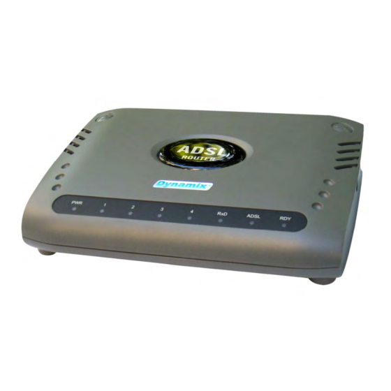
Page 19: Front Panel
2.1.2 Front Panel The 4 Port ADSL Router’s LEDs indicators display information about the device’s status. Steady green light indicates the router is powered on. 1 : LINK/ACT Steady green light indicates a valid Ethernet connection. Blinking green light indicates active Ethernet session. 2 : LINK/ACT Steady green light indicates a valid Ethernet connection. -
Page 20: Connection Mechanism
2.1.3 Connection Mechanism This section describes the hardware connection mechanism of your 4 Port ADSL Router on your Local Area Network (LAN) connect to the Internet, how to configure 4 Port ADSL Router for Internet access or how to manually configure your Internet connection. You need to prepare the following items before you can establish an Internet connection through your 4 Port ADSL Router: A computer which must have an installed Ethernet Adaptor and an Ethernet Cable. - Page 21 Follow the following steps or instructions for connecting your 4 Port ADSL Router : Turn off your computer. Connect the ADSL port of your 4 Port ADSL Router to the splitter DSL port with a RJ-11 cable. Connect the Ethernet cable ( RJ-45 ) from your 4 Port ADSL Router to the Ethernet Adaptor in your computer.
-
Page 22: For One Port Adsl Router
2.2 For One Port ADSL Router 2.2.1 Back Panel The back panel of the 1 Port ADSL Router contains WAN/LAN Connection, USB Port Connection and Power Switch. ADSL Port for connecting the 1 Port ADSL Router to the ADSL Service Provider. -
Page 23: Front Panel
2.2.2 Front Panel The 1 Port ADSL Router’s LEDs indicators display information about the device’s status. Steady green light indicates the router is powered on. Steady green light indicates a valid Ethernet connection. Blinking LINK/ACT green light indicates active Ethernet session. Blinking green light indicates an active WAN session. -
Page 24: Connection Mechanism
2.2.3 Connection Mechanism This section describes the hardware connection mechanism of your 1 Port ADSL Router on your Local Area Network (LAN) connect to the Internet, how to configure 1 Port ADSL Router for Internet access or how to manually configure your Internet connection. You need to prepare the following items before you can establish an Internet connection through your 1 Port ADSL Router: A computer which must have an installed Ethernet Adaptor and an Ethernet Cable. - Page 25 Follow the following steps or instructions for connecting your 1 Port ADSL Router : Turn off your computer. Connect the ADSL port of your 1 Port ADSL Router to the splitter DSL port with a RJ-11 cable. 10. Connect the Ethernet cable ( RJ-45 ) from your 1 Port ADSL Router to the Ethernet Adaptor in your computer.
-
Page 26: Chapter 3. Administrator's Computer Setting
Chapter 3. Administrator’s Computer Setting The instruction in this section will help you configure your computers to be able to communicate with this ADSL Router. Computers access the Internet using a protocol called TCP/IP (Transmission Control Protocol/ Internet Protocol). Each computer on your network must have TCP/IP installed and selected as its networking protocol. -
Page 27: Windows 98/Me
3.1 Windows 98/ME 4/1 Port ADSL Router P 26... -
Page 28: Windows 2000
3.2 Windows 2000 4/1 Port ADSL Router P 27... -
Page 29: Windows Xp
3.3 Windows XP 4/1 Port ADSL Router P 28... -
Page 30: Chapter 4. Device Administration
Chapter 4. Device Administration For your convenience, an Administrative Utility has been programmed into the ADSL Router. This chapter will explain all the functions in this utility. All ADSL Router based administrative tasks are performed through this web utility. 4.1 Login Levels of Access : There are two levels of access rights/privileges for the ADSL Router: Administrator : User name admin, the administrator account has complete read/write access on all pages (Status, Configuration, Admin Privilege, and Firewall Configuration). - Page 31 “Admin” and “User” passwords can be changed after login. Refer to Section 4.3.2.8 for User Password configuration and Section 4.3.3.9 for Admin Password configuration for further instruction. Upon entering the address into the web browser, the configurable main page with all the device status information will pop up as shown in Figure below : System Information : Show the current ADSL Router Firmware version, Customer Software version, Current ISP setting and PPP Status...
-
Page 32: Quick Setup
4.2 Quick Setup The Quick Setup is meant to help you install the ADSL Router quickly and easily. Click “Automatic Setup” and follow the steps describe below to complete your installation. 4/1 Port ADSL Router P 31... -
Page 33: Quick Setup : Automatic Setting
4.2.1 Quick Setup : Automatic Setting Select the presetting country form the list. STEP 1. For 1483 Bridged LLC encapsulation, there are two available IP mode : Bridge Mode : Click “Enable” or “Disable” for the connection mode. Check your ISP for the connection/setting details. IP Mode : Click “Dynamic IP”... - Page 34 For PPPoA VC-Mux and PPPoE LLC encapsulation : Manually enter your “Service Name”, “User Name” and “Password” which will be provided by your ISP. Check your ISP for the details. 4/1 Port ADSL Router P 33...
- Page 35 Click “Save Setting” after your choice. STEP 2. The ADSL Router system will reboot and activate your setting. Click “Back To Home” after the reboot process. Connection to the Internet is available after the above process. 4/1 Port ADSL Router P 34...
-
Page 36: Quick Setup : Manual Setup
4.2.2 Quick Setup : Manual Setup “Manual Setup” allows you to manually configure the ADSL Router step by step by selecting User Configured in the field. Click “Manual Setup” and follow the installation wizard to complete the installation process. Manually enter the “Encapsulation” type, “VPI” and “VCI” setting. Check your ISP for the setting/configuration details. - Page 37 A. Bridge Mode: Bridge Mode is used when there is one PC connected to the LAN-side Ethernet port. IEEE 802.1D method of transport bridging is used to bridge between the WAN (ADSL) side and the LAN (Ethernet) side, i.e., to store and forward. There are two encapsulation type for Bridge Mode : 1483 Bridged IP LLC : If 1483 Bridged IP LLC mode is selected, select “Enable”...
- Page 38 For “Dynamic IP”, nothing have to fill in, just click “Save Setting” to activate your configuration. For “Static IP”, please check with your ISP to fill in the necessary setting before clicking “ Save Setting” to activate your configuration. “Set IP” : Static IP Settings are for users who have a Static IP Address (WAN side) from their ISP.
- Page 39 “DNS Proxy” : The DNS proxy on the ADSL Router records the available DNS servers and forwards DNS query messages to one of DNS servers. “DNS Proxy Enable/Disable” : When the DNS Proxy is Disabled, the LAN port does not process the DNS query message. For the DHCP requests from local PCs, the DHCP server will set the user-configured DNS server as the DNS server.
- Page 40 iii. PPPoE VC-Mux : If PPPoE VC-Mux mode is selected, manually enter your “User Name”, “Input Password” and “Confirm Password” then click “Save Setting” after your configuration. Check with your ISP for the VPI/VCI setting details. PPPoE LLC : If PPPoE LLC mode is selected, manually enter your “User Name”, “Input Password”...
-
Page 41: Advanced Mode
4.3 Advanced Mode The Advanced Mode describe the detail instruction on installation/configurations for advance user. Click “Advanced Setup” icon to login the configuration/setting pages. 4/1 Port ADSL Router P 40... -
Page 42: Advanced Setup-Status
4.3.1 Advanced Setup—Status Click “Advanced Setup”, the device “Home Page” or “Main Status” window will pop up. It shows all the current setting/configuration information of the ADSL Router. 4/1 Port ADSL Router P 41... -
Page 43: Status - Main Status
4.3.1.1 Status – Main Status The links under the Main Status column are associated with the pages that represent the status of system (computer and ADSL Router) and interfaces (Connections). This includes LAN, WAN and ADSL status. These pages can be viewed and modified by both user and admin accounts. - Page 44 System Info Shows the firmware version you are using. Firmware Version Customer Software Shows the software control code from. Version Shows the ADSL Router’s IP Address. The default value is IP Address 10.0.0.2. Subnet Mask Shows the Subnet Mask of the WAN (ADSL) Interface MAC Address Shows the WAN MAC Address of the WAN (ADSL) Interface.
-
Page 45: Status - Ppp
4.3.1.2 Status – PPP The PPP Status page shows the status of each PPP session for each PPP interface. This page contains information that is dynamic and will refresh every 8 seconds. Note: PPP interfaces can be created, modified, and deleted in the PPP Configuration page. PPP (Point-to-Point Protocol): The table displays the following fields: Connection Name: This is user defined. - Page 46 PPP X: Connecting... This is displayed while the PPP session is attempting to connect to the ISP. PPP X: Connect ERROR This is displayed when a connection cannot be made due to an error. PPP X: is currently not connected This is displayed when a disconnect attempt is made on a session that is not currently connected.
-
Page 47: Status - Adsl
4.3.1.3 Status – ADSL The ADSL Status page shows the ADSL physical layer or link status. The information displayed on this page is either inherent to the ADSL Router or set by the ADSL Central Office (CO) DSLAM, neither of which cannot be changed by the user. This page contains information that is dynamic and will refresh every 2 seconds. - Page 48 Startup Attempts: This field displays the number of ADSL connection attempts after loss of showtime. A connection attempt is recorded only if showtime is attained. Max TX Power: This field displays the transmit output power level of the CPE (Customer Premise Equipment), which is the transmit output power level of the ADSL Router.
-
Page 49: Advanced Setup - Configuration
4.3.2 Advanced Setup — Configuration The links under Configuration column are associated to the pages that represent the configurations of system and interfaces. These pages can be viewed and modified by both user and admin accounts. Note: When any settings are changed, please go to the Save Settings page to save the new setting(s) and reboot the ADSL Router. -
Page 50: Configuration-Wan
4.3.2.1 Configuration—WAN The WAN configuration page allows you to set the configuration for the WAN/ADSL ports. Before you enter the WAN Configuration page, you will be asked to select an adapter (PVC0 through PVC7) first. Once you select the adaptor, then following page will appear. 4/1 Port ADSL Router P 49... - Page 51 A. Change Adapter : Click the “Change Adapter” tab to select the PVC Setting. Click “Submit after your choice to view the setting/configurations details. Main Setting : Virtual Circuit: Select Enable to activate the current PVC configuration. The current PVC is displayed at the top of the page in parenthesis.
- Page 52 DHCP Client : DHCP Client: This is to enable or disable (default) the ADSL Router WAN as a DHCP client, where the ISP would be the DHCP server. DHCP Client is generally used in the following encapsulations: 1483 Bridged IP LLC, 1483 Routed IP LLC, 1483 Bridged IP VC-MUX, 1483 Routed IP VC-Mux, and Classical IP over ATM.
- Page 53 Service Name: The Service Name of the PPP session is required by some ISPs. If the ISP does not provide the Service Name, please leave it blank. User Name: Enter the PPP user name (provided by the ISP). The User Name can be up to 127 characters.
- Page 54 Authentication: The different types of available authentications are: Auto: When auto is selected, PAP mode will run by default. However, if PAP fails, then CHAP will run as the secondary protocol. This is the default setting. PAP: Password Authentication Procedure. Authentication is done through username and password.
- Page 55 Not necessary to relay multicast routing between two ADSL PVCs or two interfaces in LAN side. Special purpose multicast packet (such as RIP 2 packet) should run without Interference. Note: Before the IGMP mode is enabled; please go to the Miscellaneous Configuration page to enable the IGMP proxy.
- Page 56 Note: In the case of multiple PVCs, CBR specified PVCs will have higher priority than PVCs with UBR. For example, the CBR PVCs will take their bandwidth and the remaining bandwidth will be split among the UBR PVCs. In the case of total PVC CBR bandwidth exceeding ADSL upstream, the total upstream bandwidth will be shared proportionally to the bandwidth allocated for each CBR PVC.
- Page 57 Example: VBR-nrt : This example is provided to further explain the dynamics of VBR-nrt. A PVC has a service category of VBR-nrt with the following parameters: PCR = 400 kbps SCR = 100 kbps MBS = 22 cells (Note that 22 cells * 48 bytes/cell = 1056 bytes) If the PVC has been idle for a while (meaning it has accumulated a MBS of 22 cells), and it just has two packets of the same size (1000 bytes) to send.
-
Page 58: Configuration-Lan
4.3.2.2 Configuration—LAN The LAN configuration allows you to set the configuration for the LAN port. A. LAN IP : LAN IP Address & Subnet Mask: The LAN IP Address is what the computer uses to identify and communicate with the ADSL Router (this is the address you enter in the address bar of Internet Explorer to access these pages). - Page 59 DHCP Server : Dynamic Host Configuration Protocol (DHCP) is a communications protocol that allows network administrators to manage and assign IP addresses to computers within the network. DHCP provides a unique address to a computer in the network which enables it to connect to the Internet through Internet Protocol (IP).
- Page 60 C. Ethernet Mode Setting : The Ethernet Mode configuration page allows you to set the LAN port into the following modes: AutoSense: The ADSL Router will automatically sense which mode to use, selecting between 100 Mbps Full Duplex, 100 Mbps Half Duplex, 10 Mbps Full Duplex, and 10 Mbps Half Duplex.
-
Page 61: Configuration-Ppp
4.3.2.3 Configuration—PPP PPP Configuration : The PPP Configuration page allows you to configure multiple PPP sessions for each PVC. Multiple PPP sessions enables you to set up different connection settings and be able to toggle/choose those settings for each PVC. The ADSL Router can support up to total of 16 PPP sessions, and each PVC can support up to 8 PPP sessions. - Page 62 MRU: The MRU (Maximum Receive Unit) field indicates the maximum size IP packet that the peer of PPP connection (this device) can receive. During the PPP negotiation, the peer of the PPP connection will indicate its MRU and will accept any value up to that size. The actual MTU of the PPP connection will be set to the smaller of the two (MTU and the peer’s MRU).
- Page 63 Example : Create a PPP session and connect it to the ISP? To create and connect a PPP session, follow the steps below: First you must create a PPP account. To do this, go to PPP Configuration page and click on PPP Account Configuration.
- Page 64 Password: Enter the PPP password (provided by the ISP). The Password is not needed to delete or modify the account. The Password can be up to 127 characters. PPP Account Configuration Status table will be displayed at the bottom of this page to show all the accounts (Table headings: Account Name and User Name).
- Page 65 Enable/Disable Idle Timer Filter : All Traffic will reset Idle Timer (ignore filter below): Selecting this option will disable the PPP Idle Timeout filter and allow any traffic through any protocol or port to reset the idle timer. The only dependency is that the traffic must correspond with the Filter Application (Inbound and/or Outbound).
- Page 66 III. Filter Details : The table displayed in the Filter Details section of the page shows all the current Idle Filters. Traffic must match the criteria of one of these filters in order to cause an Idle Timeout, unless All Traffic will reset Idle Timer is selected. As a default and starting point for configuration, WWW browsing (HTTP), FTP, and Telnet related packets are part of the filter table.
- Page 67 Port #: This is the Port through which the PPP session can be activated. The default filters are: HTTP TCP Port: 80 FTP TCP Port: 20 and 21 Telnet TCP Port: 23 DNS UDP: 53 Action: You can add a rule by entering the appropriate information, selecting Add on the Action dropdown menu, and clicking Submit.
-
Page 68: Configuration-Nat
4.3.2.4 Configuration—NAT The NAT Configuration page allows you to set the configuration for the Network Address Translation. The NAT module provides Dynamic Network Address and Port Translation (Dynamic NAPT) capability between LAN and multiple WAN connections, and the LAN traffic is routed to appropriate WAN connections based on the destination IP addresses and the Route Table. - Page 69 Session Name: This field allows you to select the session from the configured NAT Session Name Configuration. User’s IP: This field allows you to assign the IP address to map the corresponding NAT/NAPT sessions. Number of NAT Configurations: This field displays the total number of NAT Sessions entered.
-
Page 70: Configuration - Virtual Server
4.3.2.5 Configuration – Virtual Server Virtual Servers are used for port forwarding from the WAN to LAN networks. The Virtual Server Configuration page allows you to set the configuration of the Virtual Server. All UDP/TCP ports are protected from intrusion. If any specific local PCs need to be mapped to the UDP/TCP port on WAN side, please input the mappings here. - Page 71 4/1 Port ADSL Router P 70...
-
Page 72: Configuration - Bridge Filtering
4.3.2.6 Configuration – Bridge Filtering Bridge Filtering allows packets to be forwarded or blocked, depending on the MAC address. The Bridge Filtering configuration page allows you to set the configuration of MAC filtering. There can be up to 4 different Bridge Filtering configurations. Source MAC: This is the Source MAC to block or from which to forward. - Page 73 Example : Q1 : How do I forward packets with MAC address 000002fa6fab to destination MAC 000003dc8faa through IP protocol? ANS : First go to the Bridge Filtering page under Configuration. Then type 000002fa6fab in the ID Source MAC field, 000003dc8faa in the Destination MAC field, and 0800 in the Type field. If bridge filtering is not already enabled, select Yes under the Enable Bridge Filtering field.
-
Page 74: Configuration-Dns
4.3.2.7 Configuration—DNS The DNS Configuration page allows you to set the configuration of the DNS proxy. For the DHCP requests from local PCs, the DHCP server will set the LAN port IP as the default DNS server. Thus, all DNS query messages will come into LAN port first. The DNS proxy on the ADSL Router records the available DNS servers and forwards DNS query messages to one of DNS servers. - Page 75 4/1 Port ADSL Router P 74...
-
Page 76: Configuration - User Password Configuration
4.3.2.8 Configuration – User Password Configuration The User Password Configuration page allows the user or admin to set the password for the user account. The User Password can be up to 65 characters (excluding ‘&’). Note: User Account cannot be used to access FTP server. Save Configuration: Clicking this will link the user to the Save Settings / Reboot page. -
Page 77: Configuration - Save Setting/Reboot
4.3.2.9 Configuration – Save Setting/Reboot The Save Settings / Reboot page allows you to either save the new configuration to the flash and reboot the ADSL Router or simply reboot the ADSL Router without saving changes. Save & Reboot: Click this to apply all changes. Reboot Only: Do this to discard all changes since last save. -
Page 78: Advanced Setup - Admin Privilege
4.3.3 Advanced Setup – Admin Privilege The links under Admin Privilege are only accessible when user is logged in as Admin. Regular user account does not have authorization to view or alter the content on the pages in the Admin Privilege section. 4/1 Port ADSL Router P 77... -
Page 79: Admin Privilege - Wan Status
4.3.3.1 Admin Privilege – WAN Status The WAN Status page shows the information and status of WAN PVCs. WAN: This field displays the IP address, Subnet Mask and MAC address for the WAN (ADSL) interface. Use the Virtual Circuit selection to select different PVCs for status display. -
Page 80: Admin Privilege - Atm Status
4.3.3.2 Admin Privilege – ATM Status The ATM Status page shows all the statistics information of ATM cells. This page contains information that is dynamic and will refresh every 2 seconds. Reset Counters: This button allows user to reset the ATM Status counter. ATM Status Fields: Tx Bytes, Rx Bytes, Tx Cells, Rx Cells, Rx HEC Errors, Tx Mgmt Cells, Tx CLP0 Cells, Rx CLP0 Cells, Tx CLP1 Cells, Rx CLP1 Cells, Rx Errors, Tx Errors, and Rx Misrouted Cells. -
Page 81: Admin Privilege - Adsl Configuration
4.3.3.3 Admin Privilege – ADSL Configuration The ADSL Configuration page allows you to set the configuration for ADSL protocols. Annex Mode Config : This allows you to manually configure the ADSL Router for Annex A or Annex B mode by selecting User Configured and choosing the Annex Mode in the next field. -
Page 82: Admin Privilege - Route Table
4.3.3.4 Admin Privilege – Route Table The Route Table page displays the routing table and allows you to manually enter a routing entry. The routing table will display the routing status of Destination, Netmask, Gateway, and Interface. The interface br0 indicates the USB interface; lo0 indicates the loopback interface; ppp1 indicates the PPP interface. - Page 83 A user-defined route entry is added to the Routing Table whenever the system provides an environment that makes the route entry applicable. It is removed from the Routing Table whenever the route entry becomes not applicable. e.g. If the route entry’s Gateway is associated with a dynamic Network Interface but the connection is not established, then the route entry does not appear in the Routing Table.
-
Page 84: Admin Privilege - Learned Mac Table
4.3.3.5 Admin Privilege – Learned MAC Table Network bridges operate at the physical network layer. The purpose of a bridge is to connect two or more networks and enable packet sharing between them. Bridges are different from routers because they forward packets based on physical addresses, whereas routers use IP address to forward packets. Bridges must learn all the physical (MAC) addresses of the devices so it can forward the packets reliably. -
Page 85: Admin Privilege - Rip Configuration
4.3.3.6 Admin Privilege – RIP Configuration RIP (Routing Information Protocol) is a management protocol that ensures that all hosts in a particular network share the same information about routing paths. In a RIP, a host computer will send its entire routing table to another host computer every X seconds, where X is the supply interval. - Page 86 RIP: This field allows you to Enable or Disable the RIP session. The resulting RIP session will monitor all network interfaces that are currently available for messages from other RIP routers. RIP is disabled by default. Border Gateway: RIP implements Border Gateway as specified in RFC 1058 and RFC 1723. This limits all subnet routes and host routes to routers within that same network.
- Page 87 Advance Configuration : The RIP Per Interface Configuration page allows you to set the configuration for each Interface (PVCs, PPP Sessions, USB and LAN). Interface: This field allows you to choose the Interface (PVCs, PPP Sessions, USB and LAN), for the RIP to be configured. The available selections are: IP Ethernet 0, IP USB 0, IP PVC0...IP PVC7, IP BridgeMux 0, and any PPP user defined sessions (maximum of 16) Enable: This field allows you to Enable (Yes) or Disable (No) the specified interface for RIP.
-
Page 88: Admin Privilege - Misc Configuration
4.3.3.7 Admin Privilege – Misc Configuration The Miscellaneous Configuration page allows you to set miscellaneous configurations for the following: HTTP, FTP, TFTP, DMZ, Command Line Interface, DHCP, PPP, IGMP, and SNTP. HTTP Server Access : This field allows you to configure where these Web pages can be accessed from. All: When this field is checked, it allows both WAN and LAN access to the Web pages. - Page 89 FTP Server : FTP server: This field allows you to enable or disable the FTP server connection. System default is Enabled. Disable WAN side FTP access: This will disable WAN side access to the FTP server, default is Disabled. TFTP server: This field allows you to enable or disable the TFTP connection. System default is Disabled.
- Page 90 DHCP : DHCP Relay : NONE: This will disable the DHCP server. Note that this setting will override the DHCP Server Enable/Disable on the LAN configuration page. DHCP Server (default): Select this to activate the DHCP server. DHCP Relay: If it is enabled, the DHCP requests from local PCs will forward to the DHCP server runs on WAN side.
- Page 91 Connect PPP when ADSL link is up: If this option is enabled, the bridge/router will connect the PPP session whenever an ADSL connection is established. If this option is disabled, the PPP session will not connect whenever the ADSL Showtime is reached. System default is Enabled.
-
Page 92: Admin Privilege - Tcp Status
4.3.3.8 Admin Privilege – TCP Status The TCP Status page shows the statistics for all TCP connections. This page contains information that is dynamic and will refresh every 2 seconds. Reset Counters: This button allows user to reset the TCP Status counter. General: Total Packets, Data Packets, Data Bytes, Out of Order Packets, Out of Order Bytes. -
Page 93: Admin Privilege - Admin Password Configuration
4.3.3.9 Admin Privilege – Admin Password Configuration The Admin Password Configuration page allows you to set the password for administrator. The Admin password is same as the FTP password, so it must have at least 8-characters for the FTP to work. -
Page 94: Admin Privilege - Reset To Factory Default
4.3.3.10 Admin Privilege – Reset To Factory Default The Reset to Factory Default page allows you to reset the ADSL Router to original factory default configuration (factory.reg). 4/1 Port ADSL Router P 93... -
Page 95: Admin Privilege - Diagnostic Test
4.3.3.11 Admin Privilege – Diagnostic Test The Diagnostic Test page shows the test results for the connectivity of the physical layer and protocol layer for both LAN and WAN sides. This page will continually refresh every 2 seconds until all tests are complete. - Page 96 Checking LAN Connection : Testing Ethernet LAN Connection: This test passes if the Ethernet LAN interface is working properly. Checking ADSL Connection : Testing ADSL Synchronization: This test checks your ADSL Router to see if it can successfully negotiate and establish an ADSL connection with your service provider. The test returns PASS if an ADSL connection is established.
- Page 97 of the current VC are configured correctly. This test returns SKIPPED if the “AAL5 Connection” test does not return PASS. Test PPP Layer Connection: This test returns PASS if your login name and password have passed authentication with your service provider. If this test returns FAIL, run this test again a few minutes after this test is completed, especially if your PPP connection has just been improperly disconnected.
- Page 98 Query DNS for www.conexant.com: This test returns PASS if the host name can be resolved to an IP address though your domain name servers. This test returns FAIL if the host name can not be resolved successfully. If this test returns FAIL, run this test again a few minutes after this test is completed. Ping www.conexant.com: This test returns PASS if the host specified by your ISP can be reached through a ping request.
-
Page 99: Admin Privilege - System Log
4.3.3.12 Admin Privilege – System Log The System Log page shows the events triggered by the system. This page contains information that is dynamic and will refresh every 5 seconds. Clear Log: This field allows you to clear the current contents of the System Log. Save Log: This field allows you to save the current contents of the System Log by right click “HERE”... -
Page 100: Admin Privilege - Local Code Image Update
4.3.3.13 Admin Privilege – Local Code Image Update The Code Image Update page allows you to upgrade the image code locally. Browse the location of file, firmware.dlf or bootrom.dlf file, and click the Upload to start the update. The ADSL Router will reboot as part of the process of updating code. 4/1 Port ADSL Router P 99... -
Page 101: Admin Privilege - Network Firmware Image Update
4.3.3.14 Admin Privilege – Network Firmware Image Update The Network Firmware Image Update page allows you to upgrade the image code from the remote FTP server. Assume an FTP server stores the updated image firmware.dlf on Internet. Click Image Download to initiate the updating. -
Page 102: Admin Privilege - Boot Code Image Update
4.3.3.15 Admin Privilege – Boot Code Image Update Assume an FTP server stores the updated image boorom.dlf on Internet. Click Image Download to initiate the updating. The ADSL Router will reboot as part of the process of updating code. 4/1 Port ADSL Router P 101... -
Page 103: Admin Privilege - Firewall
4.3.3.16 Admin Privilege – Firewall Note : A Statefull Packet Inspection (SPI) firewall is an optional feature that may or may not be included in your ADSL Router. A firewall is a method of implementing common as well as user defined security policies in an effort to keep intruders out. -
Page 104: Advanced Options - Protection Policy
4.3.3.16.1.1 Advanced Options – Protection Policy Protection Policies defend against common methods of attacking a network and computers within the network. Some of these attacks are classified as a DoS (Denial of Service). DoS is an attack in which a network or components of a network are disabled, usually by overloading traffic on the network, in order to prevent authorized and legitimate users to access network resources. - Page 105 Reassembly Attack checking: Reassembly Attack is a type of DoS attack that exploits the weakness of the IP protocol reassembly process. As discussed earlier in this user guide, packets undergo fragmentation when they exceed a certain maximum size. Certain criteria define the packet fragmentation process so that packets can be reassembled properly.
-
Page 106: Advanced Options - Hacker Log
4.3.3.16.1.2 Advanced Options – Hacker Log This page allows you to configure which Protection Policy (see previous section) violations to log for admin viewing. Alert Log: Enable/Disable for SYN Flooding, Ping of Death, IP Spoofing, and Win Nuke (all of these are explained in the previous section). Enable to log violations of individual policies. General Log: Deny Policies: Enabling this will add Deny Policy violations to the log. -
Page 107: Advanced Options - Service Filtering
4.3.3.16.1.3 Advanced Options – Service Filtering Service Filtering allows you to disable service requests from certain sources. These are the Service Request sources that can be disabled : Ping from External Network Telnet from External Network FTP from External Network DNS from External Network IKE from External Network RIP from External Network... -
Page 108: Firewall Databases - Ip Group
4.3.3.16.2.1 Firewall Databases – IP Group The IP Group lets you specify IP Addresses (Single or Range) and Subnet Masks and assign them to a group name for easy use when configuring inbound and outbound policies for the firewall. IP Entry Name: This is the name you assign to the group of IP addresses and subnet masks. The IP Entry Name can be up to 19 characters. -
Page 109: Firewall Databases - Service Group
4.3.3.16.2.2 Firewall Databases – Service Group The Service Group lets you specify a Port and assign it to a group name for easy use when configuring inbound and outbound policies for the firewall. Service Entry Name: This is the name you assign to the group containing the port number. The Service Name Entry can be up to 19 characters. -
Page 110: Firewall Databases - Time Window
4.3.3.16.2.3 Firewall Databases – Time Window The Time Window lets you specify certain time periods and assign them to a group name for easy use when configuring inbound and outbound policies for the firewall. Time Window Name: This is the name you assign to the group that is given the time designation. -
Page 111: Inbound/Outbound Policies - Inbound Policy
4.3.3.16.3.1 Inbound/Outbound Policies – Inbound Policy The Inbound Policy allows you to filter inbound (from the WAN into the user side LAN) packets based on a set of rules. This enables you to deny access from different sources and thus increase security. A table of inbound policies is displayed with the following information. - Page 112 Note: The Inbound Policy works in a Top-Down fashion according to the Inbound Policy Table. This means that the firewall will apply the policies in order from the top of the table to the bottom. It is critical for both security and user accessibility to the WAN to have inbound policies in the correct order.
- Page 113 IP Range: Selecting this will enable you to select a range of IP Addresses to which the policy will apply. The first IP Address in the range must be entered into the first IP Address entry field and the last IP Address in the range must be entered into the second IP Address entry field.
- Page 114 Time Window Filtering: This field allows you to select a certain time frame from the Time Group in which this policy will be active. See section 4.3.3.16.2.3 for more information on Time Groups. DB: Short for Database, this field allows you to select a user-defined IP Group for the Src IP and Dest IP fields and a user-defined Service Group for the Dest Port.
-
Page 115: Inbound/Outbound Policies - Outbound Policy
4.3.3.16.3.2 Inbound/Outbound Policies – Outbound Policy The Outbound Policy allows you to filter outbound (from the user side LAN to the WAN) packets based on a set of rules. This enables you to deny access to different sources and thus increase security. A table of outbound policies is displayed with the following information. - Page 116 Note: The Outbound Policy works in a Top-Down fashion according to the Outbound Policy Table. This means that the firewall will apply the policies in order from the top of the table to the bottom. It is critical for both security and user accessibility to the WAN to have outbound policies in the correct order.
- Page 117 IP Range: Selecting this will enable you to select a range of IP Addresses to which the policy will apply. The first IP Address in the range must be entered into the first IP Address entry field and the last IP Address in the range must be entered into the second IP Address entry field.
- Page 118 Time Window Filtering: This field allows you to select a certain time frame from the Time Group in which this policy will be active. See section 6.6 for more information on Time Groups. DB: Short for Database, this field allows you to select a user-defined IP Group for the Src IP and Dest IP fields and a user-defined Service Group for the Dest Port.
- Page 119 The configuration should look like the following when complete: Note: It should be clear now how critical it is to sort the policies in the correct order. For example, if policies one and two were switched, there would be NO HTTP access to any computer in the LAN.
- Page 120 Allow access from Src (LAN) IP range 10.0.0.3~10.0.0.6 to any Des (WAN) IP through port 20 (FTP), through any protocol. The configuration should look like the following when complete: 4/1 Port ADSL Router P 119...
-
Page 121: Advanced Mode - Manage Public Servers
4.3.4 Advanced Mode – Manage Public Servers The Manage Public Severs are used for port forwarding from the WAN to LAN networks. The Virtual Server Configuration page allows you to set the configuration of the Virtual Server. All UDP/TCP ports are protected from intrusion. If any specific local PCs need to be mapped to the UDP/TCP port on WAN side, please input the mappings here. - Page 122 Private Port: This field allows you to enter the port number of the Private Network (LAN or internal network). In most cases, the private port number is same as public port number. This port number cannot be seen from the WAN side. Host IP Address: This field allows you to enter the private network IP address for the particular server.
-
Page 123: Status
4.4 Status Shows all the Configuration/Setting/Status of the ADSL Router. 4.4.1 Status – Current Setting Click “Current Setting” to display the current Configuration/Setting of the ADSL Router. 4/1 Port ADSL Router P 122... -
Page 124: Status - System Log
4.4.2 Status – System Log The System Log page shows the events triggered by the system. This page contains information that is dynamic and will refresh every 5 seconds. Clear Log: This field allows you to clear the current contents of the System Log. Save Log: This field allows you to save the current contents of the System Log by right click “HERE”... - Page 125 The System Log records: ADSL Layer : ADSL Link detected ADSL Link connected ADSL Link disconnected ATM Layer : ATM detected ATM connected ATM disconnected ATM setting up VPI/VCI PPP Layer : PPP authenticated PPP invalid user name or password PPP unable to connect with PPP server IP Layer : IP protocol up...
-
Page 126: Appendix A : Network Address Translation
Appendix A : Network Address Translation Network Address Translation (NAT) translates the IP address a network (LAN) to a different IP address known by another network (WAN). This gives an outside network the ability to distinguish and communicate with a device on the inside network, as the inside network has a private set of IP addresses assigned by the DHCP server, which are not know to the outside network. -
Page 127: Basic Nat
A.1 Basic NAT Basic Network Address Translation (NAT) enables outbound sessions for the hosts in a private network to gain 0access the external network. Facts of Basic NAT: Basic NAT allows hosts in a private network to transparently access the external network. Basic NAT maps only one IP addresses in the private domain to each IP address in the public domain. -
Page 128: Static Napt
A.2 Static NAPT NAPT, also known as NAT-PAT, stands for Network Address Translation and Port Address Translation. An extension of Basic NAT, NAPT enables outbound sessions so that the hosts in a private network to access the external network. Facts of NAPT: NAPT multiplexes traffic from the internal network and presents it to the Internet as if it is coming from only one IP address. -
Page 129: Functional Descriptions
A.3 Functional Descriptions This section describes various NAT mechanisms for both outbound and inbound session operations. Together, they provide a mechanism to connect a realm with private addresses to an external realm with globally unique registered addresses. The NAT module allows outbound access with either static or dynamic sessions. Inbound access is normally blocked but selective inbound sessions may be enabled. -
Page 130: Outbound Access
A.3.1 Outbound Access The NAT module implements two modes for outbound sessions: NAT mode and NAPT mode. NAT Mode: NAT mode implements the Basic NAT functionality. 1. Static session mapping is required for any local host to access the public domain. 2. - Page 131 ping for a period of time, let the session expire, then restart the ping. The expiration time differs from protocol to protocol. 7. With dynamic WAN interfaces, the Route table changes as links go up and down. Since NAPT is based on Route Table, NAT packet forwarding may behave differently from time to time.
-
Page 132: Inbound Access
A.3.2 Inbound Access Inbound access is normally blocked; however, selective inbound sessions may be enabled. The NAT module implements two types of inbound access control: Virtual Server and Demilitarized Zone (DMZ). Virtual Server: The term “Virtual Server” came from the concept of subdividing one physical system into multiple “virtual”... -
Page 133: Appendix B Frequently Asked Questions
Appendix B Frequently Asked Questions The Frequently Asked Questions addresses common questions regarding ADSL Router settings. Some of these questions are also found throughout the guide, in the sections to which they reference. Q1. How do I determine if a link between the Ethernet card (NIC) and the ADSL Router has been established? ANS: A ping test would determine if a connection is established between your ADSL Router and computer. - Page 134 Q6. How do I forward packets with MAC address 000002fa6fab to destination MAC 000003dc8faa through IP protocol? ANS: First go to the Bridge Filtering page under Configuration. Then type 000002fa6fab in the ID Source MAC field, 000003dc8faa in the Destination MAC field, and 0800 in the Type field. If bridge filtering is not already enabled, select Yes under the Enable Bridge Filtering field.
- Page 135 Q9. How can I find/verify my ADSL Router and/or computer Ethernet MAC Address? ANS: Follow the following instructions for the appropriate operating system: Windows NT/2000/XP : Click on Start Menu¡ ÷ (All) Programs¡ ÷ Accessories¡ ÷ Command Prompt (MS-DOS Prompt in NT). Once in the command prompt, type ipconfig/all and press enter.
-
Page 136: Appendix C Troubleshooting Guide
Appendix C Troubleshooting Guide The Troubleshooting Guide provides answers to common problems regarding the ADSL Router settings, connections, and computer settings. I changed the LAN IP Address in the LAN configuration page and my PC is no longer able to detect the ADSL Router. -
Page 137: Appendix D Network Setup Guide
Appendix D Network Setup Guide To configure your computer to connect to the Internet through a LAN, refer to the instructions or help guide provided with your Operating System. It is recommended that the network address of the client PC to be configured as a dynamic IP address. This will give your DHCP server full control of IP Addresses and DNS Servers: D.1 Windows XP/2000 Click on Start Menu¡... -
Page 138: Windows 95/98/98Se/Me
D.2 Windows 95/98/98SE/Me Click on Start Menu¡ ÷ Settings¡ ÷ Control Panel. In the Control Panel, double-click the Network icon. Select the TCP/IP for the ADSL Router (i.e. TCP/IP¡ ÷ Conexant USB Network Adapter) and click the Properties button. Select the IP Address tab and click Obtain an IP address automatically. Click OK to close TCP/IP Properties and then click OK to close Network. -
Page 139: Ac Os (7.6.1 Or Higher)
D.3 AC OS (7.6.1 or higher) Select Control Panels from the Apple Menu and open the TCP/IP Control Panel. Choose the Connect via Ethernet option. Select Configure using DHCP Server option. Close and Save. 4/1 Port ADSL Router P 138... -
Page 140: Mac Os X
D.4 MAC OS X Launch System Preferences from the Apple Menu and select the Network Preference Pane. Choose Show: Built-in Ethernet. Click on the TCP/IP tab. Choose Configure: Using DHCP. Quit System Preferences. 4/1 Port ADSL Router P 139... -
Page 141: Appendix E Common Error Messages
Appendix E Common Error Messages This Appendix provides a library of common error messages, explaining how each one is obtained and how to keep them error from reoccurring. 1. Server Error: 401 Unauthorized – Access Denied This error occurs when an Invalid Login attempt is made. This is caused by an invalid user name and/or password. -
Page 142: Appendix F Glossary
Appendix F Glossary The Glossary provides an explanation of terms and acronyms discussed in this user guide. AP : Access Point: A station that transmits and receives data in a WLAN (Wireless Local Area Network). An access point acts as a bridge for wireless devices into a LAN. ATM : Asynchronous Transfer Mode: A method of transfer in which data is organized into 53-byte cell units. - Page 143 initiate a session in the private network, it can only forward packets to the private network as they are requested. DNS : Domain Name System: A method to locate and translate Domain Names into Internet Protocol (IP) addresses, where a Domain Name is a simple and meaningful name for an Internet address. DSL : Digital Subscriber Line: A technology that provides broadband connections over standard phone lines.
- Page 144 IAD : Integrated Access Device: A device that multiplexes and demultiplexes communications in the CPE onto and out of a single telephone line for transmission to the CO. IP : Internet Protocol: The method by which information is sent from one computer to another through the Internet.
- Page 145 Proxy : A device that closes a straight connection from an outside network (WAN) to an inside network (LAN). All transmissions must go through the proxy to get into or out of the LAN. This makes the internal addresses of the devices in the LAN private. PVC : Permanent Virtual Circuit: A software defined logical connection in a network;...
- Page 146 USB : Universal Serial Bus: A standard interface between a computer and a peripheral (printer, external drives, digital cameras, scanners, network interface devices, modems, etc.) that allows a transfer rate of 12Mbps. UDP : User Datagram Protocol: A protocol that is used instead of TCP when reliable delivery is not required.
Need help?
Do you have a question about the UM-A and is the answer not in the manual?
Questions and answers