Dynamix UM-A User Manual
Ethernet
Hide thumbs
Also See for UM-A:
- User manual (146 pages) ,
- Quick start manual (10 pages) ,
- Quick start manual (12 pages)
Table of Contents
Advertisement
Quick Links
Advertisement
Table of Contents

Related Manuals for Dynamix UM-A


Summary of Contents for Dynamix UM-A
- Page 1 DYNAMIX UM-A Ethernet ADSL Router User Manual for ANNEX A/B...
- Page 2 Copyright The contents of this publication may not be reproduced in any part or as a whole, stored, transcribed in an information retrieval system, translated into any language, or transmitted in any form or by any means, mechanical, magnetic, electronic, optical, photocopying, manual, or otherwise, without the prior written permission.
-
Page 3: Fcc Interference Statement
FCC Interference Statement This equipment has been tested and found to comply with the limits for a Class B digital device pursuant to Part 15 of the FCC Rules. These limits are designed to provide reasonable protection against radio interference in a residential environment. This equipment can generate, use and radiate radio frequency energy and, if not installed and used in accordance with the instructions in this manual, may cause harmful interference to radio communications. -
Page 4: Table Of Contents
Contents CHAPTER 1 INTRODUCTION................... 6 1.1 Features ........................7 1.2 Scope ........................... 9 1.3 Audience........................10 1.4 Document Structure.....................11 1.5 System Requirement ....................12 1.6 Packet Contents ......................13 CHAPTER 2 GETTING TO KNOW ETHERNET ADSL ROUTER ........14 2.1 Front Panel: ........................ 14 2.2 Back Panel: ........................ - Page 5 4.4.2 ADVANCE: Configuration -- LAN ................72 4.4.3 ADVANCE: Configuration -- PPP ................76 4.4.3.1 PPP Configuration ....................77 4.4.3.2 PPP Status Table ....................79 4.4.3.3 PPP Account Configuration .................. 80 4.4.3.4 PPP Disconnect Timer Configuration..............82 4.4.3.5 PPP Miscellaneous Configuration................. 86 4.4.3.6 PPP Q&A......................
- Page 6 4.8 ADVANCE: Firewall ....................141 4.8.1 ADVANCE: Firewall – Firewall ................142 4.8.2 ADVANCE: Firewall – Protection Policy..............143 4.8.3 ADVANCE: Firewall – Hacker Log ................. 146 4.8.4 ADVANCE: Firewall – Service Filtering..............148 4.8.5 ADVANCE: Firewall – IP Group ................149 4.8.6 ADVANCE: Firewall –...
-
Page 7: Chapter 1 Introduction
Chapter 1 Introduction Congratulations on your purchase of this outstanding Ethernet ADSL Router. ADSL is a transmission technology used to carry user data over a single twisted-pair line between the Central Office and the Customer Premises. The downstream data rates can go up to 8 Mbps. The upstream data rates can go up to 1Mbps. -
Page 8: Features
1.1 Features The Ethernet ADSL Router provides the following features: Full rate ANSI T1.413 Issue 2, ITU-T G.992.1 and ITU-T G.992.2 standards compliant. Fully compliant with Annex A/B/B(U-R2) ADSL specifications. Downstream and Upstream data rates up to 8Mbps and 1Mbps. PPPoE/PPP protocol for dial-up ADSL service. - Page 9 Firewall Support Statefull Packet Inspection ( SPI ). Support DoS ( Denial of Service ) protection. Support Service Filtering. Support Access Policies. UPnP Support UPnP functionality. Web-Based Management Firmware upgrade via FTP. Restore factory default setting via Web or hardware reset button. WAN and LAN connection statistics.
-
Page 10: Scope
1.2 Scope This document provides the descriptions and usages for the Ethernet ADSL Router’s Web pages that are used in the configuration and setting process. Both basic and advanced descriptions and concepts are discussed. To help the reader understand more about these Web pages, some questions and answers (Q&A) are appended after the definition of each Web page along with the appendices at the end of the guide. -
Page 11: Audience
1.3 Audience This document is prepared for use by those customers who purchasing this Ethernet ADSL Router and using the provided/embedded firmware. It assumes the reader has a basic knowledge of ADSL and networking. Ethernet ADSL Router P 10... -
Page 12: Document Structure
1.4 Document Structure Chapter 1 : Introduction, provides a brief introduction to the product and user guide. Chapter 2 : Getting to know Ethernet ADSL Router, provides device specifications and hardware connection mechanism. Chapter 3 : Administrator’s computer setting, provides Windows system Network’s configurations. -
Page 13: System Requirement
1.5 System Requirement Personal computer. Pentium II compatible processor and above. Internet Browser. 64 MB RAM or more. 50 MB of free disk space minimum. Ethernet Network Interface Controller ( NIC ) RJ-45 Port. Ethernet ( CAT5 ) Cable. CD-ROM Drive. Ethernet ADSL Router P 12... -
Page 14: Packet Contents
1.6 Packet Contents One Ethernet ADSL Router One CD-ROM ( Manual / Quick Setup Guide ) One Power Adapter One RJ-11 ADSL Cable One CAT-5 Ethernet Cable Ethernet ADSL Router P 13... -
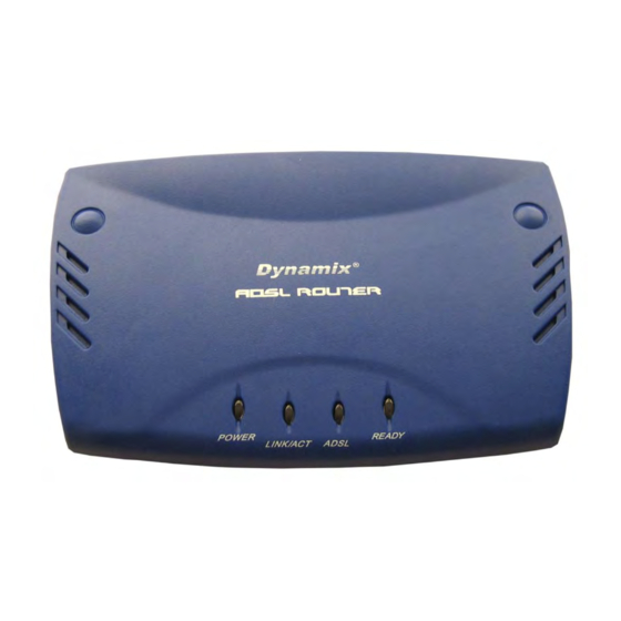
Page 15: Chapter 2 Getting To Know Ethernet Adsl Router
Chapter 2 Getting To Know Ethernet ADSL Router 2.1 Front Panel: The Ethernet ADSL Router’s LEDs indicators display information about the device’s status. POWER Lights up when the Ethernet ADSL Router is powered on. LINK/ACT Blinking when the Ethernet ADSL Router is Sending/Receiving data. Blinking when the Ethernet ADSL Router system is ready. -
Page 16: Back Panel
2.2 Back Panel: The back panel of the Ethernet ADSL Router contains ADSL, LAN, Reset Button and Power Adaptor connection. ADSL Port for connecting to the ADSL Service Provider. 10/100Mbps Ethernet Ports for connecting to the network devices. Restore the Ethernet ADSL Router’s to factory default setting. RESET 9V AC/1A or 12V DC/1A Power adapter connector. -
Page 17: Connection Mechanism
2.3 Connection Mechanism: This section describes the hardware connection mechanism of your Ethernet ADSL Router on your Local Area Network (LAN) connected to the Internet, how to configure your Ethernet ADSL Router for Internet access or how to manually configure your Internet connection. You need to prepare the following items before you can establish an Internet connection through your Ethernet ADSL Router: A computer/notebook which must have an installed Ethernet Adaptor and an Ethernet Cable. - Page 18 Following are the steps to properly connect your Ethernet ADSL Router: Turn off your computer/notebook. Connect the ADSL port of your Ethernet ADSL Router to the wall jack of the ADSL Line with a RJ-11 cable. Connect the Ethernet cable ( RJ-45 ) from your Ethernet ADSL Router to the Ethernet Adaptor in your computer.
-
Page 19: Chapter 3 Setting Up The Tcp/Ip In Windows
Chapter 3 Setting Up The TCP/IP In Windows The instruction in this chapter will help you configure your computers to be able to communicate with this Ethernet ADSL Router. Computers access the Internet using a protocol called TCP/IP ( Transmission Control Protocol/ Internet Protocol ). -
Page 20: Windows Me / 98
3.1 Windows ME / 98 Step 1: Click Start→Settings→Control Panel. Step 4: Go to IP Address icon and select Obtain an IP address Step 2: Double-click the Network icon. Step 5: Go to Gateway icon and erase all previous setting. Step 3: Go to Configuration icon, select network Step 6: Go to DNS Configuration icon, select adapter installed and click Properties. -
Page 21: Windows 2000
3.2 Windows 2000 Step 1: Click Start→Settings→Control Panel. Step 4: Select Internet Protocol (TCP/IP) and click Properties. Step 2: Double-click the Network and Dial-up Connections. Step 5: Select Obtain an IP address automatically and DNS server address automatically. Then, click OK. Step 3: Right Click the Local Area Connection and select Properties. -
Page 22: Windows Xp
3.3 Windows XP Step 1: Click Start→Control Panel→Classic View Step 4: Go to General icon, select Internet Protocol (TCP/IP) and click Properties. Step 2: Double-click the Network Connections. Step 5: Go to General icon, select Obtain an IP address automatically and DNS server address automatically. - Page 23 After your PC is configured and the system has rebooted, you can check the TCP/IP configuration using the following utility provided by your Windows system: Windows 98/ME: Click on “Start” and “Run”. In the open field, enter “winipcfg”, then press “OK”. All the Ethernet adapter information will be shown in the appears Windows.
- Page 24 Windows 2000: Click “Start” and “Run”. In the open field, enter “cmd” then click “OK”. In the command prompt, type “ipconfig /all”, then press “Enter”. All the Ethernet adapter information will be shown in the appear Windows. Check if you can get the following setting: The IP Address as 10.0.0.x The Subnet Mask as 255.0.0.0...
- Page 25 Windows XP: Click “Start” and “Run”. In the open field, enter “cmd” then click “OK”. In the command prompt, type “ipconfig /all”, then press “Enter” All the Ethernet adapter information will be shown in the appear Windows. Check if you can get the following setting: IP address as 10.0.0.x The Subnet Mask as 255.0.0.0...
-
Page 26: Chapter 4 Device Administration
Chapter 4 Device Administration For your convenience, an Administrative Utility has been programmed into the Ethernet ADSL Router. This chapter will explain all the functions in this utility. All the Ethernet ADSL Router based administrative tasks are performed through this web utility. 4.1 Login Levels of Access: There are two levels of access rights/privileges for the Ethernet ADSL Router: Administrator: User name: “admin”... - Page 27 Remember my password check box: By default, this box is not checked. Users can check this box so that Internet Explorer will remember the User name and Password for future logins. It is recommended to leave this box unchecked for security purposes. “Admin”...
- Page 28 Upon entering the address into the web browser, the configurable main page with all the device status information will pop up as shown in Figure below: Main Information: System Info: Show the current Ethernet ADSL Router Firmware version and Customer Software version which is not changeable, Country and ISP of current setting.
- Page 29 Ethernet: This field displays the total number of available interfaces for the LAN interface. The total number of available interfaces is the amount of computers that are able to hook up to the DHCP Server. Note: If there are no devices connected to the DHCP server, then a table will not appear, otherwise a table ( Table Headings: IP Address, MAC Address ) listing all devices connected to DHCP server will appear on the bottom of the page.
- Page 30 ADVANCED: The ADVANCED Mode describe the detail instruction on installation /configurations for advance user. No changes should be made to this section without a thorough understanding of networking concepts. Configuration: The links under Configuration column are associated to the pages that represent the configurations of system and interfaces.
-
Page 31: Ez Setup
4.2 EZ SETUP The EZ SETUP is meant to help you install the Ethernet ADSL Router quickly and easily. Click “Automatic Setup” and follow the steps describe below to complete your installation. Ethernet ADSL Router P 30... -
Page 32: Ez Setup: Automatic Setup
4.2.1 EZ SETUP: Automatic Setup STEP 1. Select your country from the list and note the “Encapsulation” type. The “Encapsulation” type differs in each country and there are two different kinds of setup windows wizard that will pop-up. Ethernet ADSL Router P 31... - Page 33 For the following “Encapsulation” type after clicking the “NEXT” button, the pop-up setup window wizard is shown below: PPPoA VC-Mux PPPoA LLC PPPoE LLC Manually enter your “Service Name”, “User Name” and “Password” which will be provided by your Service Provider ( ISP ). Click “SAVE” after setup. Check your ISP for the Setting/Configuration details.
- Page 34 For the following “Encapsulation” type after clicking the “NEXT” button, the pop-up set up window wizard is shown below: 1483 Bridged IP LLC Bridge Mode: Click either “Disabled” or “Enable” mode for the device to connect. Refer to your ISP for further details on proper setting and configuration. Ethernet ADSL Router P 33...
- Page 35 IP Mode: Click either the “Dynamic IP” or “Static IP” mode for the device to connect. If “Static IP” mode is chosen, more terms need to be filled before any Internet access is available. Refer to your ISP for further details on proper setting and configuration. Ethernet ADSL Router P 34...
- Page 36 STEP 2. Click “SAVE” after setup. The Ethernet ADSL Router system will save and activate your setting. Click “Return To Home” after the system’s save and reboot process. Connection to the Internet is available after the above process. Ethernet ADSL Router P 35...
-
Page 37: Ez Setup: Manual Setup
4.2.2 EZ SETUP: Manual Setup “Manual Setup” allows you to manually configure the Ethernet ADSL Router step by step by selecting User Configured in the field. Click “Manual Setup” and follow the installation wizard to complete the installation process. Manually enter the “Encapsulation” type, “VPI” and “VCI” setting. Check your ISP for the setting/configuration details. - Page 38 Check your ISP for the “VPI” setting. Connection to the Internet will fail if the “VPI” setting is not selected correctly. Range for VPI field is 0 ~ 255. VCI: A Virtual Channel Identifier is a virtual channel that is identified by a unique numerical tag that is defined by a 16-bit field in the ATM cell header.
- Page 39 Table below lists the example of the mode configurations. Bridge Mode: Bridge Mode is used when there is one PC connected to the LAN-side Ethernet port. IEEE 802.1D method of transport bridging is used to bridge between the WAN (ADSL) side and the LAN (Ethernet) side, i.e., to store and forward.
- Page 40 Router Mode: Router Mode is used when there is more than one PC connected to the LAN-side Ethernet port. This enables the ADSL WAN access to be shared with multiple nodes on the LAN. Network Address Translation (NAT) is supported so that one WAN-side IP address can be shared among multiple LAN-side devices.
- Page 41 □ Bridge Mode: After clicking the “NEXT” button, the following window wizard will pop-up : Bridge Mode: “Enable” to connect the LAN to the WAN ( Bridge the two connections ). Default is “Disabled”. IP Mode: Select either “Dynamic IP” or “Static IP” for your connection mode. Check your ISP for the setting detail.
- Page 42 Set IP Address: Static IP Settings are for users who have a Static IP Address ( WAN side ) from their ISP. “Static IP Address”: This is the static IP Address given by the ISP. ≦ ≦ ≦ ≦ Range for IP Address is x.x.x.y, where 0 255 and 1 254, default is 192.168.241.101.
- Page 43 “DNS Server”: This is the user defined DNS server URL name and IP. Default is “Disabled”. “URL Name (Add/Delete)”: This is the URL name for the DNS server. This can be up to 255 characters. “Host IP (Add Only)”: This is the IP address of the DNS Server. “SAVE”: Clicking this will link the user to the “Save Settings”...
-
Page 44: Basic
4.3 BASIC The BASIC mode shows all the system information and events triggered by the system. Ethernet ADSL Router P 43... -
Page 45: Basic: Main Information
4.3.1 BASIC: Main Information The links under the Main Information column are associated with the pages that represent the status of system ( Computer and Ethernet ADSL Router ) and interfaces ( Connections ). This includes LAN, WAN and Ethernet status. These pages can be viewed and modified by both “user” and “admin” accounts. Ethernet ADSL Router P 44... -
Page 46: System Info
4.3.1.1 System Info These fields shows the Firmware, customer software version, current country and ISP setting of this device. Firmware Version: Shows the firmware version of the current device. Customer Software Version: Shows the software control code from manufacturer. Country of Current Setting: Shows the current country setting of this Ethernet ADSL Router. ISP of Current Setting: Shows the current ISP setting of this Ethernet ADSL Router. -
Page 47: Wan
4.3.1.2 WAN These fields display the IP address, Subnet Mask and MAC address for the WAN (ADSL) interface. IP Address: Shows the Ethernet ADSL Router’s IP Address. The default value is 10.0.0.2. Subnet Mask: Shows the Subnet Mask of the WAN ( ADSL ) Interface MAC Address: Shows the WAN MAC Address of the WAN ( ADSL ) Interface. -
Page 48: Lan
4.3.1.3 LAN These fields display the IP address, Subnet Mask and MAC address for the LAN interface. IP Address: Shows the Ethernet ADSL Router’s IP Address. The default value is 10.0.0.2. Subnet Mask: Shows the Subnet Mask of the LAN Interface. MAC Address: Shows the WAN MAC Address of the LAN Interface. -
Page 49: Ethernet
4.3.1.4 Ethernet These fields display the IP address, Subnet Mask and MAC address for the LAN interface. Index: Shows the number of Ethernet device connected to the Ethernet ADSL Router. IP Address: Shows the Ethernet ADSL Router’s IP Address. The default value is 10.0.0.2. MAC Address: Shows the WAN MAC Address of the LAN Interface. -
Page 50: Basic: Ppp Status
4.3.2 BASIC: PPP Status The PPP Status page shows the status of each PPP session for each PPP interface. This page contains information that is dynamic and will refresh every 8 seconds. Note: PPP interfaces can be created, modified, and deleted in the PPP Configuration page. PPP ( Point-to-Point Protocol ): The table displays the following fields: Connection Name: This is user defined. - Page 51 Bytes Sent: Number of bytes sent by a particular PPP Connection. Bytes Received: Number bytes received by a particular PPP Connection. Connect and Disconnect: This field allows you to manually connect/disconnect the PPP connection for each PPP interface. In other words, each PPP session can be connected and disconnected individually.
- Page 52 Click “Check The WAN Configuration” button, the following information will pop-up. Refer to “ADVANCE – Configuration – WAN” section for setting details. Ethernet ADSL Router P 51...
-
Page 53: Basic: Adsl Status
4.3.3 BASIC: ADSL Status The ADSL Status page shows the ADSL physical layer or link status. The information displayed on this page is either inherent to the Ethernet ADSL Router or set by the ADSL Central Office (CO) DSLAM, neither of which cannot be changed by the user. - Page 54 Line State: This field displays the Ethernet ADSL Router connection process and status. The different states for this field are as follows: Activation: The Ethernet ADSL Router is in this state when it is attempting to start the activation process. Initialization: The Ethernet ADSL Router is initializing handshake with the CO.
- Page 55 Elapsed Time: This field displays the time of the Ethernet ADSL Router has been in operation. This is the amount of time the Ethernet ADSL Router is on, not the amount of time it is connected to the PC or in showtime status. SNR Margin: Signal to Noise Ratio ( SNR ) is the measure of signal intensity relative to the background noise.
- Page 56 Latency: Latency, synonymously delay, is the amount of time it takes for a packet of data to get from one designated point to another. This field displays the two mapping modes for latency ( Fast and Interleaved ). Ethernet ADSL Router P 55...
-
Page 57: Basic: Diagnostic Test
4.3.4 BASIC: Diagnostic Test The Diagnostic Test page shows the test results for the connectivity of the physical layer and protocol layer for both LAN and WAN sides. This page will continually refresh every 2 seconds until all tests are complete. - Page 58 Test ATM OAM Segment Loop Back: This test sends ATM OAM F5 Segment loop back request cells to the CO. This test will “PASS” if a response cell is received. Since some service providers might not support this test, it could still work even if this test “FAIL”. If this test fails consistently and the Ethernet ADSL Router seems not working, make sure the “VPI”...
- Page 59 Test PPP Layer Connection: This test returns “PASS” if your login name and password have passed authentication with your service provider. If this test returns “FAIL”, run this test again a few minutes after this test is completed, especially if your PPP connection has just been improperly disconnected.
- Page 60 Ping Primary DNS: This test returns “PASS” if the primary DNS can be reached through a ping request. The primary DNS is assigned by your service provider or obtained from your service provider by PPP or DHCP negotiation. If this test returns “FAIL”, run this test again a few minutes after this test is completed. If this test returns “FAIL”...
-
Page 61: Basic: System Log
4.3.5 BASIC: System Log The System Log page shows the events triggered by the system. This page contains information that is dynamic and will refresh every 5 seconds. Clear Log: This field allows you to clear the current contents of the System Log. Save Log: This field allows you to save the current contents of the System Log by right click “HERE”... - Page 62 ATM Layer ATM detected ATM connected ATM disconnected ATM setting up VPI/VCI PPP Layer: PPP authenticated PPP invalid user name or password PPP unable to connect with PPP server IP Layer: IP protocol up PPP IP address PPP Gateway IP address PPP DNS Primary IP address PPP DSN Secondary IP address Ethernet ADSL Router P 61...
-
Page 63: Advance
4.4 ADVANCE The “ADVANCE” Mode describe the detail instruction on installation/configurations for advance user. No changes should be made to this section without a thorough understanding of networking concepts. The links under Configuration column are associated to the pages that represent the configurations of system and interfaces. -
Page 64: Advance: Configuration -- Wan
4.4.1 ADVANCE: Configuration -- WAN The WAN configuration page allows you to set the configuration for the WAN/ADSL ports. Before you enter the WAN Configuration page, you will be asked to select an “Adapter” ( PVC0 through PVC7 ) first. Once you select the adaptor, press “SUBMIT”. - Page 65 Setting: Virtual Circuit: Select Enable to activate the current PVC configuration. The current PVC is displayed at the top of the page in parenthesis. Default is “Enabled” for “PVC0” and “Disabled” for “PVC1 ~ PVC7”. Bridge: Enable to connect the LAN to the WAN ( Bridge the two connections ). This is available in Bridge Mode only ( See Table below ).
- Page 66 IGMP: IGMP ( Internet Group Management Protocol ) relay/proxy specification and environment, default is “Disabled”. IGMP is available in all modes and all encapsulations. Support IGMP proxy/relay function for ADSL Bridge/Router, based on the following requirement and cases: On CO side, there must be at least one IGMP querier (Router) present. IGMP querier will send IGMP query packet.
- Page 67 Static IP Settings: Static IP Settings are for users who have a Static IP Address ( WAN side ) from their ISP. IP Address: This is the static IP Address given by the ISP. ≦ ≦ ≦ ≦ Range for IP Address is x.x.x.y, where 0 x 255 and 1 y 254, default is 192.168.241.101.
- Page 68 Service Category: This field allows you to select from the following service categories, with “UBR” as the default. UBR (Unspecified Bit Rate): When configured as UBR, traffic is delivered with best efforts but with no guarantee. This allows for fluctuation in times of temporary increase of available bandwidth.
- Page 69 □ Example: CBR and UBR This example is provided to further explain the dynamics of UBR and CBR and how different PVCs with different service category specifications coexist. In this example, the Ethernet ADSL Router upstream is 900 kbps. VBR-nrt ( Variable Bit Rate - non real time ): An PVC enabled with VBR-nrt can transmit a cell only if the PVC has a token available.
- Page 70 In the case of total PVC CBR bandwidth exceeding ADSL upstream, the total upstream bandwidth will be shared proportionally to the bandwidth allocated for each CBR PVC. □ Example: VBR-nrt This example is provided to further explain the dynamics of VBR-nrt. A PVC has a service category of VBR-nrt with the following parameters: PCR = 400 kbps SCR = 100 kbps...
- Page 71 PPP: For PPP Configuration details, refer to Section “ADVANCE – Configuration – PPP” for setting details. DHCP Client: DHCP Client: This is to enable or “Disabled” ( Default ) the Ethernet ADSL Router WAN as a DHCP client, where the ISP would be the DHCP server. This option is for non-static (dynamic) IP addresses.
- Page 72 DHCP Client is generally used in the following encapsulations: 1483 Bridged IP LLC 1483 Routed IP LLC 1483 Bridged IP VC-MUX 1483 Routed IP VC-Mux Classical IP over ATM. Host Name: When DHCP Client is “Enabled”, copy the ISP recognized Host Name here. The Host Name can be up to 19 characters.
-
Page 73: Advance: Configuration -- Lan
4.4.2 ADVANCE: Configuration -- LAN The LAN configuration page allows you to set the configuration for the LAN port. LAN IP: LAN IP Address & Subnet Mask: The LAN IP Address is what the computer uses to identify and communicate with the Ethernet ADSL Router ( This is the address you enter in the address bar of Internet Explorer to access these pages ). - Page 74 DHCP Server: Dynamic Host Configuration Protocol ( DHCP ) is a communications protocol that allows network administrators to manage and assign IP addresses to computers within the network. DHCP provides a unique address to a computer in the network which enables it to connect to the Internet through Internet Protocol ( IP ).
- Page 75 DHCP Gateway Selection: The default setting for the DHCP Gateway Selection is “Automatic”. You can select “User Defined” and specify “User Defined Gateway Address”. The DHCP server will issue the “User Defined Gateway Address” to the LAN DHCP clients. User Defined Gateway Address: The purpose for the User Defined Gateway Address is to have two gateway addresses, as the LAN IP Address at the top of the LAN Configuration page is also a gateway address.
- Page 76 Ethernet Mode Setting: The Ethernet Mode configuration page allows you to set the LAN port into the following modes ( Default is “AutoSense” ): AutoSense: The Ethernet ADSL Router will automatically sense which mode to use, selecting between 100 Mbps Full Duplex, 100 Mbps Half Duplex, 10 Mbps Full Duplex, and 10 Mbps Half Duplex.
-
Page 77: Advance: Configuration -- Ppp
4.4.3 ADVANCE: Configuration -- PPP The PPP Configuration page allows you to configure multiple PPP sessions for each PVC. Multiple PPP sessions enables you to set up different connection settings and be able to toggle/choose those settings for each PVC. The Ethernet ADSL Router can support up to total of 16 PPP sessions, and each PVC can support up to 8 PPP sessions. -
Page 78: Ppp Configuration
4.4.3.1 PPP Configuration Session Name: This field allows you to enter a Session Name. This is user defined to help distinguish different session for different PPP accounts and different PVCs. PVC: This field allows you to choose the specific PVC for the PPP session. Service Name: The Service Name of the PPP session is required by some ISPs. - Page 79 MSS: Maximum Segment Size is the largest size of data that TCP will send in a single, unfragmented IP packet. The LAN client and the WAN host will indicate their MSS during the TCP connection handshake. Range for MSS field is 0 ~ 32767, default value is 1432. Lcp Echo Interval: This is the time interval, in seconds, between PPP session connection attempts.
-
Page 80: Ppp Status Table
4.4.3.2 PPP Status Table PPP Status Table: Shows the recorded PPP session. A table will be displayed to show all the Session Names with its Adapter ( PVC number ), Mode ( PPPoA or PPPoE ), Service Name, Account to Use ( PPP Account ID ), Disconnect Timeout configuration, MRU, MTU, MSS, Authentication Mode ( Auto, CHAP or PAP ), and Auto Reconnect configuration. -
Page 81: Ppp Account Configuration
4.4.3.3 PPP Account Configuration PPP Account Configuration: To begin PPP Session configuration, you must first go to the “PPP Account Configuration” page ( As shown below ) to set up an account. The link to this page can be found on the “ADVANCE – Configuration – PPP” page. On the “PPP Account Configuration” page, you must configure the “Account ID”, “User Name”... - Page 82 PPP Account Configuration Status table will be displayed at the bottom of this page to show all the accounts ( Table headings: Account Name and User Name ). The status table does not display the password. The Number of PPP Accounts: This field displays the total number of PPP Accounts entered. Ethernet ADSL Router P 81...
-
Page 83: Ppp Disconnect Timer Configuration
4.4.3.4 PPP Disconnect Timer Configuration The “PPP Disconnect Timer Configuration” page enables you to configure what action will bring a PPP Session out of the Idle state ( Disconnected state ) and reset the Idle Timer. This is done by specifying criteria contained in packets, namely IP Protocol and Port. The Idle Timer refers to the Disconnect Timeout, specified on the PPP Configuration page. - Page 84 Enable/Disable Idle Timer Filter: All Traffic will reset Idle Timer ( Ignore filter below ): Selecting this option will disable the PPP Idle Timeout filter and allow any traffic through any protocol or port to reset the idle timer. The only dependency is that the traffic must correspond with the Filter Application ( Inbound and/or Outbound ).
- Page 85 Apply Filter: The Filter Application consists of three options that determine which sources ( LAN and/or WAN) will be able to reset the Idle Timer and reconnect the PPP session. Inbound Traffic Only: Selecting this option will allow PPP requests from the WAN side to reset the Disconnect Timeout timer.
- Page 86 Outbound Traffic Only: When this option is selected ( Default ), PPP sessions can only be activated ( Idle Timeout ) when a request is made on the LAN side to the WAN side. The disconnect timer will reset when outbound traffic is detected ( If they match the filter table criteria ).
-
Page 87: Ppp Miscellaneous Configuration
4.4.3.5 PPP Miscellaneous Configuration These options can be found on the “ADVANCE – Specific Feature -- Misc Configuration” page. PPP Half Bridge: When PPP Half Bridge is enabled, only one PC is able to access the Internet, and the DHCP server will duplicate the WAN IP address from the ISP to the local client PC. Only the PC with the WAN IP address can access the Internet. -
Page 88: Ppp Q&A
4.4.3.6 PPP Q&A If the PPP session is disconnected after the Disconnect Timeout, how can I reconnect it? You have to go to the PPP Status page, enter the correct connection number, select the Connect option in the dropdown menu, and then click Execute. This will restart the PPP secession. What can I do to ensure an always-on connection with my PPP session? There are two things you should do: Make sure you have ‘0 ‘in the Disconnect Timeout field. -
Page 89: Advance: Configuration -- Nat
4.4.4 ADVANCE: Configuration -- NAT The NAT Configuration page allows you to set the configuration for the Network Address Translation. The NAT module provides Dynamic Network Address and Port Translation ( Dynamic NAPT ) capability between LAN and multiple WAN connections, and the LAN traffic is routed to appropriate WAN connections based on the destination IP addresses and the Route Table. - Page 90 Session Name: This field allows you to select the session from the configured NAT Session Name Configuration. User’s IP: This field allows you to assign the IP address to map the corresponding NAT/NAPT sessions. Session Name Status: This table will be displayed at the middle of the page to show the Session Name with its corresponding IP Address.
- Page 91 Interface: This field allows you to choose specific WAN Interfaces ( PVC or PPP Session ) for NAT Session. The options for this field are PVC0 ... PVC7 and any PPP session that was created by the user. NAT Session Name Status: This table is displayed at the bottom of this page to show all the NAT Session Names with their corresponding WAN Interfaces.
-
Page 92: Advance: Configuration -- Dns
4.4.5 ADVANCE: Configuration -- DNS The DNS Configuration page allows you to set the configuration of the DNS proxy. For the DHCP requests from local PCs, the DHCP server will set the LAN port IP as the default DNS server. Thus, all DNS query messages will come into LAN port first. - Page 93 User Configured: When “Enabled”, the DNS proxy will use the user-configured DNS server. All DNS query messages will be sent to the DNS server. Enter the DNS IP in the DNS Server field. Select this option when the DNS Server address assigned by the ISP is known. User Configured is disabled by default.
-
Page 94: Advance: Configuration -- Adsl
4.4.6 ADVANCE: Configuration -- ADSL The ADSL Configuration page allows you to set the configuration for ADSL protocols. Annex Mode Config: This allows you to manually configure the Ethernet ADSL Router for Annex A or Annex B mode by selecting User Configured and choosing the Annex Mode in the next field. User Selected Annex Mode: This allows you to select from Annex A and Annex B. - Page 95 Wiring Selection: This field allows you to enter the wiring selection for the RJ-11. Tip/Ring is the default for the ADSL Bridge/Router without the inner/outer pair relay. Available types are Auto, Tip/Ring (default), and A/A1, where Tip/Ring is the inner-most pair of wires on the RJ11 and A/A1 is the second inner-most pair.
-
Page 96: Advance: Configuration -- Snmp
4.4.7 ADVANCE: Configuration -- SNMP Simple Network Management Protocol ( SNMP ) is an application layer protocol that is used for managing networks. There are several components that make up the SNMP structure, including agents, network management stations ( NMS ), network management protocols, and a management information base ( MIB ). - Page 97 SNMP System Identification: The System Name, System Contact, System Location, and System OID are provided to identify the SNMP NMS. The System OID is the ID number placed in all Trap reports. The System Name, System Contact, and System Location can be up to 127 characters. Default value for System OID is 1.3.6.1.4.1.4900.
-
Page 98: Advance: Status
4.5 ADVANCE: Status The links under the Status column are associated with the pages that represent the status of system ( Computer and Ethernet ADSL Router ) and interfaces ( Connections ). This includes PPP, ADSL, WAN, ATM status and MAC Table. These pages can be viewed and modified by only “admin” accounts. Ethernet ADSL Router P 97... -
Page 99: Advance: Status - Main Information
4.5.1 ADVANCE: Status – Main Information The links under the Main Information column are associated with the pages that represent the status of system. System Info: These fields shows the Firmware, customer software version, current country and ISP setting of this device. Firmware Version: Shows the firmware version you are using. - Page 100 WAN: These fields display the IP address, Subnet Mask and MAC address for the WAN ( ADSL ) interface. IP Address: Shows the Ethernet ADSL Router’s IP Address. The default value is 10.0.0.2. Subnet Mask: Shows the Subnet Mask of the WAN ( ADSL ) Interface MAC Address: Shows the WAN MAC Address of the WAN ( ADSL ) Interface.
- Page 101 Ethernet: These fields display the IP address, Subnet Mask and MAC address for the LAN interface. Index: Shows the number of Ethernet device connected to the Ethernet ADSL Router. IP Address: Shows the Ethernet ADSL Router’s IP Address. The default value is 10.0.0.2. MAC Address: Shows the WAN MAC Address of the LAN Interface.
-
Page 102: Advance: Status - Ppp Status
4.5.2 ADVANCE: Status – PPP Status The PPP Status page shows the status of each PPP session for each PPP interface. This page contains information that is dynamic and will refresh every 8 seconds. Note: PPP interfaces can be created, modified, and deleted in the PPP Configuration page. Refer to PPP Configuration Section for further information. - Page 103 Connect and Disconnect: This field allows you to manually connect/disconnect the PPP connection for each PPP interface. In other words, each PPP session can be connected and disconnected individually. Connection #: Specifies the PPP session to be connected/disconnected. Connect/Disconnect Execute: Press this button to either connect or disconnect. Connection status dialog will be displayed below the Execute button after it is pressed.
-
Page 104: Advance: Status - Adsl Status
4.5.3 ADVANCE: Status – ADSL Status The ADSL Status page shows the ADSL physical layer or link status. The information displayed on this page is either inherent to the Ethernet ADSL Router or set by the ADSL Central Office (CO) DSLAM, neither of which cannot be changed by the user. - Page 105 Initialization: The Ethernet ADSL Router is initializing handshake with the CO. Training: This is a part of the handshake process with the CO. Channel Analysis: This is a part of the handshake process with the CO. Exchange: This is a part of the handshake process with the CO. Down: This indicates that the ADSL connection is down.
- Page 106 SNR Margin: Signal to Noise Ratio ( SNR ) is the measure of signal intensity relative to the background noise. The SNR Margin is the amount of increased noise that can be tolerated while maintaining the designated BER (Bit Error Rate ). The SNR Margin is set by Central Office DSLAM. If the SNR Margin is increased, bit error rate performance will improve, but the data rate will decrease.
-
Page 107: Advance: Status - Wan Status
4.5.4 ADVANCE: Status – WAN Status The WAN Status page shows the information and status of WAN PVCs. WAN: This field displays the IP address, Subnet Mask and MAC address for the WAN ( ADSL ) interface. Use the Virtual Circuit selection to select different PVCs for status display. Virtual Circuit: Select the Virtual Circuit that you want to release/renew, select the appropriate option on the menu dropdown and click “EXECUTE”. -
Page 108: Advance: Status - Atm Status
4.5.5 ADVANCE: Status – ATM Status The ATM Status page shows all the statistics information of ATM cells. This page contains information that is dynamic and will refresh every 2 seconds. Reset Counters: This button allows user to reset the ATM Status counter. ATM Status Fields: Tx Bytes, Rx Bytes, Tx Cells, Rx Cells, Rx HEC Errors, Tx Mgmt Cells, Tx CLP0 Cells, Rx CLP0 Cells, Tx CLP1 Cells, Rx CLP1 Cells, Rx Errors, Tx Errors, and Rx Misrouted Cells. -
Page 109: Advance: Status - Learned Mac Table
4.5.6 ADVANCE: Status – Learned MAC Table Network bridges operate at the physical network layer. The purpose of a bridge is to connect two or more networks and enable packet sharing between them. Bridges are different from routers because they forward packets based on physical addresses, whereas routers use IP address to forward packets. -
Page 110: Advance: System Management
4.6 ADVANCE: System Management The links under System Management are only accessible when user is logged in as “Admin”. Regular user account does not have authorization to view or alter the content on the pages in the System Management section. Ethernet ADSL Router P 109... -
Page 111: Advance: System Management - All Status
4.6.1 ADVANCE: System Management – All Status The All Status pages show the complete information and status of the Ethernet ADSL Router. This page contains information that is dynamic and will refresh every 5 seconds. Ethernet ADSL Router P 110... - Page 112 Ethernet ADSL Router P 111...
- Page 113 Ethernet ADSL Router P 112...
- Page 114 Ethernet ADSL Router P 113...
-
Page 115: Advance: System Management - Diagnostic Test
4.6.2 ADVANCE: System Management – Diagnostic Test The Diagnostic Test page shows the test results for the connectivity of the physical layer and protocol layer for both LAN and WAN sides. This page will continually refresh every 2 seconds until all tests are complete. - Page 116 Test ATM OAM Segment Loop Back: This test sends ATM OAM F5 Segment loop back request cells to the CO. This test will pass if a response cell is received. Since some service providers might not support this test, it could still work even if this test fails. If this test fails consistently and the Ethernet ADSL Router seems not working, make sure the VPI and VCI are configured correctly.
- Page 117 Test PPP Layer Connection: This test returns PASS if your login name and password have passed authentication with your service provider. If this test returns FAIL, run this test again a few minutes after this test is completed, especially if your PPP connection has just been improperly disconnected.
- Page 118 Ping Primary DNS: This test returns PASS if the primary DNS can be reached through a ping request. The primary DNS is assigned by your service provider or obtained from your service provider by PPP or DHCP negotiation. If this test returns FAIL, run this test again a few minutes after this test is completed. If this test returns FAIL consistently and your Ethernet ADSL Router seems to not be working, check to make sure your statically assigned primary DNS IP address is configured correctly or DHCP client is enabled with the current VC.
-
Page 119: Advance: System Management - System Log
4.6.3 ADVANCE: System Management – System Log The System Log page shows the events triggered by the system. This page contains information that is dynamic and will refresh every 5 seconds. Clear Log: This field allows you to clear the current contents of the System Log. Save Log: This field allows you to save the current contents of the System Log by right click “HERE”... - Page 120 ATM Layer ATM detected ATM connected ATM disconnected ATM setting up VPI/VCI PPP Layer PPP authenticated PPP invalid user name or password PPP unable to connect with PPP server IP Layer IP protocol up PPP IP address PPP Gateway IP address PPP DNS Primary IP address PPP DSN Secondary IP address Ethernet ADSL Router P 119...
-
Page 121: Advance: System Management - Reset To Default
4.6.4 ADVANCE: System Management – Reset to Default The Reset to Factory Default page allows you to reset the Ethernet ADSL Router to original factory default configuration. SUBMIT: Click “SUBMIT” button to restore the Ethernet ADSL Router’s to factory default setting. The “Rebooting”... -
Page 122: Advance: System Management - Code Image Update
4.6.5 ADVANCE: System Management – Code Image Update The Code Image Update page allows you to upgrade the image code locally. Click “IMAGE DOWNLOAD” to enable the upgrading process. The following window wizard will pop-up. Browse the location of file, “firmware.dlf” or “bootrom.dlf” file, and click the “IMAGE DOWNLOAD” to start the update. -
Page 123: Advance: System Management - Admin Password
4.6.6 ADVANCE: System Management – Admin Password The Admin Password Configuration page allows you to set the password for administrator. The Admin password is same as the FTP password, so it must have at least 8-characters for the FTP to work. -
Page 124: Advance: System Management - User Password
4.6.7 ADVANCE: System Management – User Password The User Password Configuration page allows the user or admin to set the password for the user account. The User Password can be up to 65 characters ( Excluding “&” ). Note : User Account cannot be used to access FTP server. Ethernet ADSL Router P 123... -
Page 125: Advance: Specific Feature
4.7 ADVANCE: Specific Feature The links under Specific Feature are only accessible when user is logged in as Admin. Regular user account does not have authorization to view or alter the content on the pages in the Specific Feature section. Ethernet ADSL Router P 124... -
Page 126: Advance: Specific Feature - Virtual Server
4.7.1 ADVANCE: Specific Feature – Virtual Server Virtual Servers are used for port forwarding from the WAN to LAN networks. The Virtual Server Configuration page allows you to set the configuration of the Virtual Server. All UDP/TCP ports are protected from intrusion. If any specific local PCs need to be mapped to the UDP/TCP port on WAN side, please input the mappings here. - Page 127 Host IP Address: This field allows you to enter the private network IP address for the particular server. Well-known TCP/IP ports are listed in Table as shown below. ADD/DELETE: Click “ADD” or “DELETE” button to activate your setting. Ethernet ADSL Router P 126...
-
Page 128: Advance: Specific Feature - Bridge Filtering
4.7.2 ADVANCE: Specific Feature – Bridge Filtering Bridge Filtering allows packets to be forwarded or blocked, depending on the MAC address. The Bridge Filtering configuration page allows you to set the configuration of MAC filtering. There can be up to 4 different Bridge Filtering configurations. Source MAC: This is the Source MAC to block or from which to forward. - Page 129 How do I forward packets with MAC address 000002fa6fab to destination MAC 000003dc8faa through IP protocol? Ans: First go to the Bridge Filtering page under Configuration. Then type 000002fa6fab in the ID Source MAC field, 000003dc8faa in the Destination MAC field, and 0800 in the Type field.
-
Page 130: Advance: Specific Feature - Misc Configuration
4.7.3 ADVANCE: Specific Feature – Misc Configuration The Miscellaneous Configuration page allows you to set miscellaneous configurations for the following: HTTP, FTP, TFTP, DMZ, Command Line Interface, DHCP, PPP, IGMP, and SNTP. Ethernet ADSL Router P 129... - Page 131 HTTP Server Access: This field allows you to configure where these Web pages can be accessed from. All: When this field is checked, it allows both WAN and LAN access to the Web pages. This is the system default. Restricted LAN: This field allows the Web pages access from LAN side. Restricted WAN Specified IP &...
- Page 132 DHCP Relay: If it is enabled, the DHCP requests from local PCs will forward to the DHCP server runs on WAN side. To have this function working properly, please disable the NAT to run on router mode only, disable the DHCP server on the LAN port, and make sure the routing table has the correct routing entry.
-
Page 133: Advance: Specific Feature - Route Table
4.7.4 ADVANCE: Specific Feature – Route Table The Route Table page displays the routing table and allows you to manually enter a routing entry. The routing table will display the routing status of Destination, Netmask, Gateway, and Interface. The interface “br0”... - Page 134 All user defined route entries kept in the CPE memory during run time are saved to flash when the user chooses to save and reboot the CPE. When the CPE restarts, it reloads all saved user-defined routes to the CPE memory and tries to apply to the system. A user-defined route entry is added to the Routing Table whenever the system provides an environment that makes the route entry applicable.
-
Page 135: System Default Gateway Configuration
4.7.4.1 System Default Gateway Configuration The system-wide Default Gateway provides three options: Auto (default), User-selected Network Interface, and None. None: This field allows you to choose to have no Default Gateway in the CPE Auto: This field allows you to enable the Ethernet ADSL Router to automatically decide the Default Gateway. -
Page 136: Route Configuration
4.7.4.2 Route Configuration Destination: This field allows you to enter the remote network or host IP address for the static routing. Netmask: This field allows you to enter the Subnet Mask for the static routing. Gateway: This field allows you to enter the IP address of the gateway device that allows the router to contact the remote network or the host for Specified IP or select an Interface for the Gateway. -
Page 137: Advance: Specific Feature - Rip Configuration
4.7.5 ADVANCE: Specific Feature – RIP Configuration RIP ( Routing Information Protocol ) is a management protocol that ensures that all hosts in a particular network share the same information about routing paths. In a RIP, a host computer will send its entire routing table to another host computer every X seconds, where X is the supply interval. - Page 138 The RIP messages that can be received and processed are based on two configuration parameters: RIP Version number and Multicast: The RIP Configuration page allows you to set the configuration for the system wide configuration of RIP. The actual RIP configuration is in the RIP Per Interface Configuration. RIP: This field allows you to Enable or Disable the RIP session.
- Page 139 Supplier Interval: This field allows you to enter the Supplier Interval timer in seconds. This timer specifies how often the RIP sends announcements as a RIP Supplier. Range for Supplier Interval field is 0 ~ 2147483647, default value is 30. Expire Timeout: This field allows you to enter the Expire Timeout in seconds.
-
Page 140: Rip Per Interface Configuration
4.7.5.1 RIP Per Interface Configuration The RIP Per Interface Configuration page allows you to set the configuration for each Interface ( PVCs, PPP Sessions, USB and LAN ). Interface: This field allows you to choose the Interface ( PVCs, PPP Sessions, USB and LAN ), for the RIP to be configured. - Page 141 Listener: This field allows you to select the Listener Mode (RIP Receive) V1: The listener receives the RIPv1 only. V2: The listener receives the RIPv2 only. V1+V2: This listener receives the both RIPv1 and RIPv2. Current RIP Settings: This field displays the each interface’s RIP status. Ethernet ADSL Router P 140...
-
Page 142: Advance: Firewall
4.8 ADVANCE: Firewall A firewall is a method of implementing common as well as user defined security policies in an effort to keep intruders out. Firewalls work by analyzing and filtering out IP packets that violate a set of rules defined by the firewall administrator. -
Page 143: Advance: Firewall - Firewall
4.8.1 ADVANCE: Firewall – Firewall Firewall Enabled/Disabled: This option “Enabled/Disabled” all the protection provided on these pages. SUBMIT: Click “SUMBIT” after setup. Ethernet ADSL Router P 142... -
Page 144: Advance: Firewall - Protection Policy
4.8.2 ADVANCE: Firewall – Protection Policy Protection Policies defend against common methods of attacking a network and computers within the network. Some of these attacks are classified as a DoS ( Denial of Service ). DoS is an attack in which a network or components of a network are disabled, usually by overloading traffic on the network, in order to prevent authorized and legitimate users to access network resources. - Page 145 Land Attack checking: Land attack is a type of DoS attack that works by sending a spoofed packet containing the same source and destination IP address and port ( The victim’s IP address ). This packet contains a connection request, resulting in a handshake process. At the end of the handshake, the victim sends out an ACK ( ACKnowledge ) request.
- Page 146 ICMP Redirection checking: Also known as an ICMP storm attack or smurf attack, ICMP Redirection is another form of DoS. This attack is performed by sending ICMP echo requests to a broadcast network node. The return IP address is spoofed and replaced by the victim’s own address, causing it to send the request back to itself.
-
Page 147: Advance: Firewall - Hacker Log
4.8.3 ADVANCE: Firewall – Hacker Log This page allows you to configure which Protection Policy ( See previous section ) violations to log for admin viewing. Alert Log: “Enabled/Disabled” for SYN Flooding, Ping of Death, IP Spoofing, and Win Nuke ( All of these are explained in the previous section ). - Page 148 SUBMIT: Click “SUMBIT” after setup. Ethernet ADSL Router P 147...
-
Page 149: Advance: Firewall - Service Filtering
4.8.4 ADVANCE: Firewall – Service Filtering “Service Filtering” allows you to disable service requests from certain sources. These are the Service Request sources that can be disabled: Ping from External Network Telnet from External Network FTP from External Network DNS from External Network IKE from External Network RIP from External Network DHCP from External Network... -
Page 150: Advance: Firewall - Ip Group
4.8.5 ADVANCE: Firewall – IP Group The “IP Group” lets you specify IP Addresses ( Single or Range ) and Subnet Masks and assign them to a group name for easy use when configuring inbound and outbound policies for the firewall. IP Entry Name: This is the name you assign to the group of IP addresses and subnet masks. - Page 151 Subnet Mask: This will let you specify a range of subnet masks for a given group. ADD/MODIFY: Click “ADD/MODIFY” button to “ADD” or “MODIFY” the corresponding policy. Ethernet ADSL Router P 150...
-
Page 152: Advance: Firewall - Service Group
4.8.6 ADVANCE: Firewall – Service Group The “Service Group” lets you specify a Port and assign it to a group name for easy use when configuring inbound and outbound policies for the firewall. Service Entry Name: This is the name you assign to the group containing the port number. The Service Name Entry can be up to 19 characters. -
Page 153: Advance: Firewall - Time Window
4.8.7 ADVANCE: Firewall – Time Window The “Time Window” lets you specify certain time periods and assign them to a group name for easy use when configuring inbound and outbound policies for the firewall. Time Window Name: This is the name you assign to the group that is given the time designation. The Time Window Name can be up to 19 characters. -
Page 154: Advance: Firewall - Inbound Policy
4.8.8 ADVANCE: Firewall – Inbound Policy The “Inbound Policy” allows you to filter inbound ( From the WAN into the user side LAN ) packets based on a set of rules. This enables you to deny access from different sources and thus increase security. A table of inbound policies is displayed with the following information. - Page 155 Inbound Policy: IP Address: This field specifies the IP address or addresses to which the policy applies. Both the source IP ( SrcIP ) and destination IP ( DesIP ) are specified here. Port #: This field specifies the Port number to which the policy applies. Both the source port ( SrcPort ) and destination port ( DesPort ) are specified here.
- Page 156 Note: The Inbound Policy works in a Top-Down fashion according to the Inbound Policy Table. This means that the firewall will apply the policies in order from the top of the table to the bottom. It is critical for both security and user accessibility to the WAN to have inbound policies in the correct order.
- Page 157 Dest IP: This specifies the Destination IP for the Inbound Policy. This is the internal ( LAN side, behind the firewall ) IP address or addresses and network that will be affected by the policy. See Src IP above for configuration detail. Src Port: This specifies the Source Port for the Inbound Policy.
- Page 158 Deny: Selecting this will cause the policy to deny packet transfer from the Src IP through the Src Port to travel through the Dest Port to the Dest IP. All of these are specified above and must be configured by the user. Time Window Filtering: This field allows you to select a certain time frame from the Time Group in which this policy will be active.
-
Page 159: Advance: Firewall - Outbound Policy
4.8.9 ADVANCE: Firewall – Outbound Policy The Outbound Policy allows you to filter outbound ( From the user side LAN to the WAN ) packets based on a set of rules. This enables you to deny access to different sources and thus increase security. A table of outbound policies is displayed with the following information. - Page 160 Outbound Policy: IP Address: This field specifies the IP address or addresses to which the policy applies. Both the source IP ( SrcIP ) and destination IP ( DesIP ) are specified here. Port #: This field specifies the Port number to which the policy applies. Both the source port ( SrcPort ) and destination port ( DesPort ) are specified here.
- Page 161 Dn: Short for down, clicking on this button will move the corresponding policy down one space in the table. Note: The Outbound Policy works in a Top-Down fashion according to the Outbound Policy Table. This means that the firewall will apply the policies in order from the top of the table to the bottom.
- Page 162 Mask Range: Selecting this will enable you to select a network to which the policy will apply. The Network IP Address must be entered into the first entry field and the Subnet Mask of this Network IP address must be entered into the second entry field. Dest IP: This specifies the Destination IP for the Inbound Policy.
- Page 163 Filtering Action: This specifies what action the policy takes: Allow: Selecting this will cause the policy to allow packet transfer from the Src IP through the Src Port to travel through the Dest Port to the Dest IP. All of these are specified above and must be configured by the user.
-
Page 164: Inbound/Outbound Policy Sample Configuration
4.8.10 Inbound/Outbound Policy Sample Configuration This is a sample Inbound/Outbound configuration meant to guide you in making your own configurations. This configuration does not necessarily provide proper security, it is meant only as a sample to display the functionality of the Inbound and Outbound Policies. Ethernet ADSL Router P 163... -
Page 165: Inbound Policy
4.8.10.1 Inbound Policy □ Sample Configuration: You want your firewall to have the following properties: Accept all http IP addresses, except for 204.35.82.1 Grant FTP access from 101.64.35.4 ( External ) to 10.0.0.3, 10.0.0.4, 10.0.0.5, and 10.0.0.6 ( All internal ). Deny all access to FTP Server 10.0.0.6 on the weekend. - Page 166 Thus, the configuration of the following should be moved down the first entry to the end of the list, otherwise all incoming packets will be dropped. Ethernet ADSL Router P 165...
-
Page 167: Outbound Policy
4.8.10.2 Outbound Policy □ Sample Configuration: You want to deny all access to the WAN except for the following: HTTP access from any IP through TCP. Any access from 10.0.0.3 through any protocol. FTP Access from 10.0.0.3~10.0.0.6 through any protocol Converting the access requirements from above so that the Outbound Policy can understand them yields the following: Deny all access from any Src ( LAN ) IP to any Des ( WAN ) IP through any source or... -
Page 168: Appendix A: Network Address Translation
Appendix A: Network Address Translation Network Address Translation (NAT) translates the IP address a network (LAN) to a different IP address known by another network (WAN). This gives an outside network the ability to distinguish and communicate with a device on the inside network, as the inside network has a private set of IP addresses assigned by the DHCP server, which are not know to the outside network. -
Page 169: Basic Nat
A.1 Basic NAT Basic Network Address Translation (NAT) enables outbound sessions for the hosts in a private network to gain 0access the external network. Facts of Basic NAT: Basic NAT allows hosts in a private network to transparently access the external network. Basic NAT maps only one IP addresses in the private domain to each IP address in the public domain. -
Page 170: Static Napt
A.2 Static NAPT NAPT, also known as NAT-PAT, stands for Network Address Translation and Port Address Translation. An extension of Basic NAT, NAPT enables outbound sessions so that the hosts in a private network to access the external network. Facts of NAPT: NAPT multiplexes traffic from the internal network and presents it to the Internet as if it is coming from only one IP address. -
Page 171: Functional Descriptions
A.3 Functional Descriptions This section describes various NAT mechanisms for both outbound and inbound session operations. Together, they provide a mechanism to connect a realm with private addresses to an external realm with globally unique registered addresses. The NAT module allows outbound access with either static or dynamic sessions. Inbound access is normally blocked but selective inbound sessions may be enabled. -
Page 172: Outbound Access
A.3.1 Outbound Access The NAT module implements two modes for outbound sessions: NAT mode and NAPT mode. □ NAT Mode: NAT mode implements the Basic NAT functionality. 1. Static session mapping is required for any local host to access the public domain. 2. - Page 173 inactivity timer expires. Thus, changes to the Route Table may not change the NAT packet forwarding on existing sessions. This may create confusion in some cases. For example, there are two WAN connections: WAN1 is the default route and goes to internet, WAN2 has an internal server behind it and a manual route entry is entered to reach that internal server.
-
Page 174: Inbound Access
A.3.2 Inbound Access Inbound access is normally blocked; however, selective inbound sessions may be enabled. The NAT module implements two types of inbound access control: Virtual Server and Demilitarized Zone (DMZ). □ Virtual Server: The term "Virtual Server" came from the concept of subdividing one physical system into multiple "virtual"... - Page 175 4. One popular use of this feature is when inbound connections to a range of ports are required and it is impractical or impossible to accommodate them via port mappings. 5. The DMZ opens all ports on this particular local host to all unsolicited traffic, therefore posing some security risk.
-
Page 176: Application Layer Gateways (Algs)
A.3.3 Application Layer Gateways (ALGs) Application Layer Gateways (ALG) may also be referred to as Application Specific Gateway or Application Level Gateway. Although the address translation itself is application independent, it does create complications. Some protocols such as FTP, DNS, and SIP require payload monitoring and alteration to traverse through NAT. ALGs are needed to accompany NAT to perform these complicate tasks. -
Page 177: Appendix B: Frequently Asked Questions
Appendix B: Frequently Asked Questions The Frequently Asked Questions addresses common questions regarding Ethernet ADSL Router settings. Some of these questions are also found throughout the guide, in the sections to which they reference. How do I determine if a link between the Ethernet card (NIC) and the Ethernet ADSL Router has been established ? Ans. - Page 178 How do I create a PPP session and connect it to the ISP ? Ans. To create and connect a PPP session, follow the steps below: First you must create a PPP account. To do this, go to PPP Configuration page and click on PPP Account Configuration.
- Page 179 How can I find/verify my Ethernet ADSL Router and/or computer Ethernet MAC Address? Ans. Follow the following instructions for the appropriate operating system: Windows NT/2000/XP: Click on Start Menu (All) Programs Accessories Command Prompt (MS-DOS Prompt in NT). Once in the command prompt, type ipconfig/all and press enter.
- Page 180 Computer (NIC) MAC Address Network Adaptor MAC Address What is MAC Address? Ans. Short for Media Access Control Address. It is a hardware address that uniquely identifies each node of a Ethernet networking device. This address is usually permanent. What is NAT ( Network Address Translation ) and what is it used for? Ans.
- Page 181 What is the maximum IP addresses supported by this Ethernet ADSL Router? Ans. The Ethernet ADSL Router will support up to 253 IP addresses. Ethernet ADSL Router P 180...
-
Page 182: Appendix C: Troubleshooting Guide
Appendix C: Troubleshooting Guide The Troubleshooting Guide provides answers to common problems regarding the Ethernet ADSL Router settings, connections, and computer settings. The Ethernet ADSL Router does not work ( None of the LEDs light up ) Ans. Check the following: 1. - Page 183 LAN ( Link/Act ) LED does not light up. Ans. Check the following: 1. Make sure that the LAN cable are securely connected to the 10/100Base-T port. 2. Make sure that you are using the correct cable type for your Ethernet equipment. 3.
- Page 184 Ethernet ADSL Router is unable to access the Internet. Ans. Check the following: 1. Setup your Ethernet ADSL Router again: Launch your browser enter the Ethernet ADSL Router’s IP address http://10.0.0.2. Enter the “Username” and “Password” then press “Enter” to log in. Proceed the “EZ SETUP –...
- Page 185 Testing LAN path to your Ethernet ADSL Router. Ans. To verify whether the LAN path from your PC to your Ethernet ADSL Router is properly connected, you can “Ping” the Ethernet ADSL Router with the following procedures: 1. From the Windows toolbar, click “Start” and select “Run”. 2.
-
Page 186: Appendix D: Upnp Setting On Windows Xp
Appendix D: UPnP Setting on Windows XP D.1 Adding UPnP: If you are running Microsoft Windows XP, it is recommended to add the UPnP component to your system. Proceed as follows: Click “Start” “Settings” then “Control Panel”. The “Control Panel” window appears. Click “Add or Remove Programs”. Ethernet ADSL Router P 185... - Page 187 The “Add or Remove Programs” window appears. Click “Add/Remove Windows Components”. The “Windows Components Wizard” appears. Select “Networking Services” in the Components list and click “Details”. Ethernet ADSL Router P 186...
- Page 188 Ethernet ADSL Router P 187...
- Page 189 The “Networking Services” window appears. Select “Universal Plug and Play” and click “OK”. Click “Next” to start the installation and follow the instructions in the Windows Components Wizard. Note : System may ask for original Windows XP CD-ROM. Insert the CD-ROM and direct Windows to the proper location of the CD-ROM.
- Page 190 A “Completing the Windows Components Wizard” will appears indicating the installation was successful. Click “Finish” to quit. Ethernet ADSL Router P 189...
-
Page 191: Appendix E: Glossary
Appendix E: Glossary The Glossary provides an explanation of terms and acronyms discussed in this user guide. AP: Access Point: A station that transmits and receives data in a WLAN (Wireless Local Area Network). An access point acts as a bridge for wireless devices into a LAN. ATM: Asynchronous Transfer Mode: A method of transfer in which data is organized into 53-byte cell units. - Page 192 CO: Central Office: In a local loop, a Central Office is where home and office phone lines come together and go through switching equipment to connect them to other Central Offices. The distance from the Central Office determines whether or not an ADSL signal can be supported in a given line. CPE: Customer Premises Equipment.
- Page 193 FEC: Forward Error Correction: An error correction technique in which a data packet is processed through an algorithm that adds extra error correcting bits to the packet. If the transmitted message is received in error, these bits are used to correct the errored bits without retransmission. Firewall: A firewall is a method of implementing common as well as user defined security policies in an effort to keep intruders out.
- Page 194 HNP: Home Network Processor Host: In context of Internet Protocol, a host computer is one that has full two way access to other computers on the Internet. IAD: Integrated Access Device: A device that multiplexes and demultiplexes communications in the CPE onto and out of a single telephone line for transmission to the CO.
- Page 195 MTU: Maximum Transmission Unit: The largest size packet that can be sent by the modem. If the network stack of any packet is larger than the MTU value, then the packet will be fragmented before the transmission. During the PPP negotiation, the peer of the PPP connection will indicate its MRU and will accept any value up to that size.
- Page 196 RIP: Routing Information Protocol: A management protocol that ensures that all hosts in a particular network share the same information about routing paths. In a RIP, a host computer will send its entire routing table to another host computer every X seconds, where X is the supply interval. The receiving host computer will in turn repeat the same process by sending the same information to another host computer.
- Page 197 Trellis Code: An advanced method of FEC (Forward Error Correction). When enabled, it makes for better error checking at the cost of slower packet transmission. Setting Trellis Code to Disabled will cause increased packet transmission with decreased error correction. TTL: Time To Live: A value in an IP packet that indicates whether or not the packet has been propagating through the network too long and should be discarded.
Need help?
Do you have a question about the UM-A and is the answer not in the manual?
Questions and answers