Table of Contents
Advertisement
Quick Links
Advertisement
Table of Contents

Related Manuals for Dynamix ANEXX A


Summary of Contents for Dynamix ANEXX A
- Page 2 Copyright The contents of this publication may not be reproduced in any part or as a whole, stored, transcribed in an information retrieval system, translated into any language, or transmitted in any form or by any means, mechanical, magnetic, electronic, optical, photocopying, manual, or otherwise, without the prior written permission.
-
Page 3: Ce Declaration Of Conformity
FCC Interference Statement This equipment has been tested and found to comply with the limits for a Class B digital device pursuant to Part 15 of the FCC Rules. These limits are designed to provide reasonable protection against radio interference in a residential environment. This equipment can generate, use and radiate radio frequency energy and, if not installed and used in accordance with the instructions in this manual, may cause harmful interference to radio communications. -
Page 4: Table Of Contents
CHAPTER 1 INTRODUCTION... 1 1.1 Features ... 2 1.2 Scope ... 5 1.3 Audience... 6 1.4 Document Structure... 7 1.5 System Requirement ... 8 1.6 Packet Contents ... 9 CHAPTER 2 KNOWING THE 4 PORTS 11G WIRELESS ADSL2/2+ ROUTER ... 10 2.1 Front Panel: ... - Page 5 4.3.2 CONFIG - LAN Setup ... 59 4.3.2.1 LAN Setup - LAN Configuration... 60 4.3.2.1.1 LAN Configuration Procedures ... 61 4.3.2.1.2 LAN Configuration - Unmanaged... 62 4.3.2.1.3 LAN Configuration – Obtain an IP Address Automatically... 63 4.3.2.1.4 LAN Configuration – PPP IP Address ... 64 4.3.2.1.5 LAN Configuration –...
- Page 6 4.4.14.1 Access Control Configuration Procedure ...113 4.4.15 ADVANCED – Save All ...114 4.5 WIRELESS ...115 4.5.1 WIRELESS - Setup ...116 4.5.1.1 WIRELESS – Setup – User Isolation ...118 4.5.1.2 How to set up and test basic wireless connectivity ...119 4.5.2 WIRELESS - Configuration... 120 4.5.3 WIRELESS - Security ...
- Page 7 APPENDIX A: ROUTER TERMS...159 APPENDIX B: FREQUENTLY ASKED QUESTIONS ...161 APPENDIX C: TROUBLESHOOTING GUIDE...164 APPENDIX D: UPNP SETTING ON WINDOWS XP...167 APPENDIX E: GLOSSARY...171 4 Ports 11g Wireless ADSL2/2+ Router...
-
Page 8: Introduction........................................................................................... 1
Chapter 1 Introduction Congratulations on your purchase of this outstanding 4 Ports 11g Wireless ADSL2/2+ Router. This device is an IEEE 802.11g Wireless and 4 Port Switch built-in ADSL2/2+ Router that allows ADSL/ADSL2/ADSL2+ connectivity while providing Wireless LAN capabilities for residential, industries and SOHO environments. Wireless-G or the so-called 11g is the upcoming 54Mbps wireless networking standard that’s almost 5 times faster than the widely deployed Wireless-B or the so-called 11b products found in homes, businesses, and public wireless hotspots around the world. -
Page 9: Features
1.1 Features The 4 Ports 11g Wireless ADSL2/2+ Router provides the following features: Compliant to ANSI T1.413 Issue 2, ITU-T G.992.1, ITU-T G.992.2, ITU-G.992.3, ITU G.992.5 and READSL2 standards.Support all Digital Loop ITU G.992.3 annex I and J specifications.Fully compliant with Annex A/B/B (U-R2) ADSL specifications. Downstream and Upstream data rates up to 24Mbps and 1Mbps. - Page 10 IEEE 802.11g Wireless Standards IEEE 802.11b/g standards compliant. Support data rates up to 54Mbps ( Auto-Rate Capable ). Support 11g+ with data transmission rate up to 125Mbps (Optional) Support OFDM (64QAM, 16QAM, QPSK, BPSK) and DSSS (DBPSK, DQPSK, CCK) modulation. Conforms to Wireless Ethernet Compatibility Alliance (WECA) Wireless Fidelity (Wi-Fi) Standard.
- Page 11 Firewall Built in Firewall functionality. Support IP Filtering. Support MAC Filtering. Support Web Filtering. IPSec Pass-Through. Protection against IP and MAC address spoofing. UPnP Support UPnP functionality (Optional). Ethernet Standards Built-in 4 Ports 10/100Mbps Ethernet Switch which compliant with IEEE 802.3x standards Automatic MDI/MDI-X crossover for 100BASE-TX and 10BASE-T ports.
-
Page 12: Scope
1.2 Scope This document provides the descriptions and usages for the 4 Ports 11g Wireless ADSL2/2+ Router’s Web pages that are used in the configuration and setting process. Both basic and advanced descriptions and concepts are discussed. To help the reader understand more about these Web pages, some questions and answers (Q&A) are appended after the definition of each Web page along with the appendices at the end of the guide. -
Page 13: Audience
1.3 Audience This document is prepared for use by those customers who purchase the 4 Ports 11g Wireless ADSL2/2+ Router and using the provided or embedded firmware. It assumes the reader has a basic knowledge of ADSL/ADSL2/ADSL2+, Wireless and networking. 4 Ports 11g Wireless ADSL2/2+ Router... -
Page 14: Document Structure
1.4 Document Structure Chapter 1: Introduction, provides a brief introduction to the product and user guide. Chapter 2: Knowing The 4 Ports 11g Wireless ADSL2/2+ Router, provides device specifications and hardware connection mechanism. Chapter 3: Setting Up TCP/IP In Windows, provides Windows system Network’s configurations. Chapter 4: Device Administration, describes the pages found under the Admin menu. -
Page 15: System Requirement
1.5 System Requirement Check and confirm that your system confirm the following minimum requirements: Personal computer ( PC/Notebook ). Pentium II compatible processor and above. Ethernet LAN card or IEEE 802.11b or IEEE 802.11g Wireless adaptor installed with TCP/IP protocol. USB Port ( Optional ) 64 MB RAM or more. -
Page 16: Packet Contents
1.6 Packet Contents The 4 Ports 11g Wireless ADSL2/2+ Router package contains the following items : One 4 Ports 11g Wireless ADSL2/2+ Router One Power Adapter One RJ-11 ADSL Cable One CAT-5 Ethernet Cable One detachable SMA Antenna One CD-ROM ( Driver / Manual / Quick Setup Guide ) If any of the above items are damaged or missing, please contact your dealer immediately. -
Page 17: Chapter 2 Knowing The 4 Ports 11G Wireless Adsl2/2+ Router
Chapter 2 Knowing The 4 Ports 11g Wireless ADSL2/2+ Router 2.1 Front Panel: The 4 Ports 11g Wireless ADSL2/2+ Router’s LEDs indicators display information about the device’s status. Lights up when 4 Ports 11g Wireless ADSL2/2+ Router is powered on. Lights up when Wireless system is ready. -
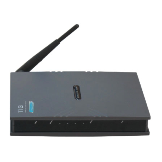
Page 18: Back Panel
2.2 Back Panel: The back panel of the 4 Ports 11g Wireless ADSL2/2+ Router contains ADSL, Ethernet Switches, Reset, Power Adapter connection, Power ON/OFF Switch and SMA connector. ADSL Port for connecting to the ADSL2/2+ Service Provider. Ports 1~4 Four 10/100Mbps Ethernet Ports for connecting to the network devices RESET Restore the 4 Ports 11g Wireless ADSL2/2+ Router to factory default setting. -
Page 19: Connection Mechanism
2.3 Connection Mechanism: This section describes the hardware connection mechanism of 4 Ports 11g Wireless ADSL2/2+ Router on your Local Area Network (LAN) connected to the Internet, how to configure your 4 Ports 11g Wireless ADSL2/2+ Router for Internet access or how to manually configure your Internet connection. You need to prepare the following items before you can establish an Internet connection through your 4 Ports 11g Wireless ADSL2/2+ Router: A computer/notebook which must have an installed Ethernet Adaptor and an Ethernet Cable, or... - Page 20 Following are the steps to properly connect your 4 Ports 11g Wireless ADSL2/2+ Router: Turn off your computer/notebook. Connect the ADSL port of your 4 Ports 11g Wireless ADSL2/2+ Router to the wall jack of the ADSL/ADSL2/ADSL2+ Line with a RJ-11 cable. Connect the Ethernet cable (RJ-45) from your 4 Ports 11g Wireless ADSL2/2+ Router (Switch ) to the Ethernet Adaptor in your computer.
-
Page 21: Chapter 3 Setting Up The Tcp/Ip In Windows
Chapter 3 Setting up the TCP/IP in Windows The instruction in this chapter will help you configure your computers to be able to communicate with this 4 Ports 11g Wireless ADSL2/2+ Router. Computers access the Internet using a protocol called TCP/IP (Transmission Control Protocol/ Internet Protocol). -
Page 22: Windows Me / 98
3.1 Windows ME / 98 Step 1: Click Start→Settings→Control Panel. Step 2: Double-click the Network icon. Step 3: Go to Configuration icon, select network adapter installed and click Properties. Step 4: Go to IP Address icon and select Step 5: Go to Gateway icon and erase all Step 6: Go to DNS Configuration icon, select 4 Ports 11g Wireless ADSL2/2+ Router Obtain an IP address. -
Page 23: Windows 2000
3.2 Windows 2000 Step 1: Click Start→Settings→Control Panel. Step 2: Double-click the Network and Dial-up Connections. Step 3: Right Click the Local Area Connection and select Properties. Step 4: Select Internet Protocol (TCP/IP) and click Step 5: Select Obtain an IP address automatically 4 Ports 11g Wireless ADSL2/2+ Router Properties. -
Page 24: Windows Xp
3.3 Windows XP Step 1: Click Start→Control Panel→Classic View. Step 2: Double-click the Network Connections. Step 3: Right Click on the Local Area Connection and select Properties. Step 4: Go to General icon, select Internet Protocol Step 5: Go to General icon, select Obtain an IP 4 Ports 11g Wireless ADSL2/2+ Router (TCP/IP) and click Properties. -
Page 25: Checking Tcp/Ip Configuration
3.4 Checking TCP/IP Configuration After your PC is configured and the system has rebooted, you can check the TCP/IP configuration using the following utility provided by your Windows system: Windows 98/ME: Click on “Start” and “Run”. In the open field, enter “Command”, then press “OK”. All the Ethernet adapter information will be shown in the appears Windows. - Page 26 Windows 2000: Click “Start” and “Run”. In the open field, enter “cmd” then click “OK”. In the command prompt, type “ipconfig /all”, then press “Enter”. All the Ethernet adapter information will be shown in the appear Windows. Check if you can get the following setting: The IP Address as 192.168.1.x The Subnet Mask as 255.255.255.0...
- Page 27 Windows XP: Click “Start” and “Run”. In the open field, enter “cmd” then click “OK”. In the command prompt, type “ipconfig /all”, then press “Enter” All the Ethernet adapter information will be shown in the appear Windows. Check if you can get the following setting: IP address as 192.168.1.x The Subnet Mask as 255.255.255.0...
-
Page 28: Chapter 4 Device Administration
Chapter 4 Device Administration For your convenience, an Administrative Utility has been programmed into 4 Ports 11g Wireless ADSL2/2+ Router. This chapter will explain all the functions in this utility. All the 4 Ports 11g Wireless ADSL2/2+ Router based administrative tasks are performed through this web utility. 4.1 Login To access the 4 Ports 11g Wireless ADSL2/2+ Router Configuration screens, follow the following steps will enable you to log into the 4 Ports 11g Wireless ADSL2/2+ Router:... - Page 29 Upon entering the address into the web browser, the configurable HOME page with all the device configuration information will pop up as shown in Figure below. HOME: The Home section show the current 4 Ports 11g Wireless ADSL2/2+ Router’s function information under different links.
- Page 30 Status Information: Shows the current device connection status. System Uptime: This field displays the time of the 4 Ports 11g Wireless ADSL2/2+ Router has been in operation. DSL Status: Shows the 4 Ports 11g Wireless ADSL2/2+ Router connection status. DSL Speed: This field displays the 4 Ports 11g Wireless ADSL2/2+ Router Downstream/Upstream data rate in Kbps Wireless RF: Show the 4 Ports 11g Wireless ADSL2/2+ Router wireless system status.
-
Page 31: Ez Setup
4.2 EZ SETUP The EZ SETUP is a presetting wizard which meant to help you install the 4 Ports 11g Wireless ADSL2/2+ Router quickly and easily. Click on “Wizard” and the following screen will pop-up. Follow the Steps describe below to complete your installation. - Page 32 STEP 1. Select your country from the Country list and the ADSL service provider from the ISP List (If there are more than two ISP in your country) and note the “Encapsulation” type and “VPI & VCI” setting. Click “Config” if you can’t find any available parameters from the presetting country list.
- Page 33 For the following “Encapsulation” type after clicking the “Next” button, the pop-up setup window wizard is shown below: PPPoA VC-Mux PPPoA LLC PPPoE LLC Manually enter your “User Name” and “Password” which will be provided by your Service Provider (ISP). Click “Apply” after setup. 4 Ports 11g Wireless ADSL2/2+ Router...
- Page 34 For countries with the following “Encapsulation” type after clicking the “Next” button, the pop-up window is shown below: 1483 Bridged LLC 1483 Routed VC-MUX In this current window, you will find Static (Fixed IP by ISP) DHCP (Get IP dynamically from ISP) Bridge 4 Ports 11g Wireless ADSL2/2+ Router THREE...
- Page 35 Static (Fixed IP by ISP): Click the radio button to enable Static (Fixed IP by ISP) option, then click “Next”, the following window will pop-up: Set Static IP: Static IP Settings are for users who have a Static IP Address ( WAN side ) from their ISP.
- Page 36 DHCP (Get IP dynamically from ISP): Click the radio button to enable DHCP (Get IP dynamically from ISP). Click “Next” after your choice and the following window will pop-up: Place a check to enable the Default Gateway. If checked, the connection becomes the default gateway to the Internet.
- Page 37 Bridge: Click the radio button to enable Bridge connection. Click “Next” after your choice and the following screen will pop-up: Select LAN: Select LAN group from the drop down manual. There are three Ethernet Bridges you can select from the drop down list or leave it in the default mode. Click “Apply”...
- Page 38 STEP 2. Click “Apply” after setup. Following windows will pop-up. The device’s system will save and activate your setting after clicking the “Apply” button. The following windows will pop up after the reboot process. Check the following items when the above window pop-up. Name: Show the ISP name selected in STEP 1.
- Page 39 A Connection Profile (Normally show the ISP Name) will be added to the left side of the configuration frame under WAN Setup. NOTE: If the final setting are differ from what you’d selected in STEP 1, click EZ SETUP the setup procedures or else check your dealer immediately for technical support. NOTE: The 4 Ports 11g Wireless ADSL2/2+ Router can be configured to maintain up to 8 Connection Profiles.
- Page 40 STEP 3. Go to “STATUS” “Modem Status” and the following window will pop-up. Check the “Connection Status”, “Us Rate” and “Ds Rate”, the numbers/data show you the actual ADSL connection speed in Kbps. STEP 4. Launch your web browser, and enter the Google Website Address: “www.google.com”...
-
Page 41: Config
4.3 CONFIG The CONFIG configuration page allows you to create new connections, edit existing connections, and configure other basic settings in WAN and LAN mode. The CONFIG Menu is divided into two sections : LAN Setup and WAN Setup. WAN Setup will be dealt with first. -
Page 42: Config - Wan Setup
4.3.1 CONFIG - WAN Setup WAN Setup: The WAN configuration page allows you to set the configuration for the WAN/ADSL ports. ADSL connections can be configured in a variety of ways depending on the ISP/WAN configuration, and the requirements of your home or office LAN. This 4 Ports 11g ADSL2/2+ Router supports the following ADSL connection types: PPPoE (RFC2516) PPPoA (RFC2364) -
Page 43: Config - Wan Setup - New Connection
4.3.1.1 CONFIG - WAN Setup – New Connection Click New Connection to setup or create a new connection profile. A New Connection is basically a virtual connection. This 4 Ports 11g Wireless ADSL2/2+ Router can support up to 8 different (Unique) virtual connections. -
Page 44: New Connection - Pppoe Connection Setup
4.3.1.1.1 New Connection - PPPoE Connection Setup PPPoE: When PPPoE Mode is selected, the following screen will pop-up. Point-to-Point Protocol ( PPP ) is a method of establishing a network connection between network hosts. PPPoE, also known as RFC 2516, adapts PPP to work over Ethernet for ADSL connections. - Page 45 Idle Timeout: Specifies that PPPoE connection should disconnect if the link has no activity detected for n seconds. This field is used in conjunction with the On-Demand feature and is enabled only when the On Demand field is checked. To ensure that the link is always active, enter a 0 in this field.
- Page 46 PVC Settings: PVC: This field allows you to choose the specific PVC for the PPP session. VPI: Virtual Path Identifier is a virtual path used for cell routing that is identified by an eight bit field in the ATM cell header. The VPI field specifies this eight bit identifier for routing. VCI: A Virtual Channel Identifier is a virtual channel that is identified by a unique numerical tag that is defined by a 16-bit field in the ATM cell header.
-
Page 47: Pppoe Configuration Procedures
4.3.1.1.1.1 PPPoE Configuration Procedures From the CONFIG main page, click on New Connection. Enter a unique name for the PPPoE connection in the Name field. The name must not have spaces and cannot begin with numbers. Select PPPoE from the Type drop down manual. The Network Address Translation (NAT) and the Firewall options are enabled by default. -
Page 48: New Connection - Pppoa Connection Setup
4.3.1.1.2 New Connection - PPPoA Connection Setup PPPoA: When PPPoA mode is selected, the following screen will pop-up. PPPoA is also known as RFC 2364. It is a method of encapsulating PPP packets over ATM cells which are carried over the ADSL line. PPP or Point-to-Point protocol is a method of establishing a network connection/session between network hosts. - Page 49 Idle Timeout: The Idle Timeout allows you to set the specific period of time, in seconds, to disconnect from the ISP if the link has no activity detected. Keep Alive: When the On-Demand option is not enabled, this value specifies the time to wait without being connected to your provider before terminating the connection.
- Page 50 VCI: A Virtual Channel Identifier is a virtual channel that is identified by a unique numerical tag that is defined by a 16-bit field in the ATM cell header. The purpose of the virtual channel is to identify where the cell should travel. The VCI field specifies this 16 bit numerical tag that determines the destination.
-
Page 51: Pppoa Configuration Procedures
4.3.1.1.2.1 PPPoA Configuration Procedures From the Setup main page, click on New Connection. Enter a unique name for the PPPoA connection in the Name field. The name must not have spaces and cannot begin with numbers. At the Type field select PPPoA. The PPPoA connection setup page is displayed as shown below. The Network Address Translation (NAT) and the Firewall options are enabled by default. -
Page 52: New Connection - Static Connection Setup
4.3.1.1.3 New Connection - Static Connection Setup Static: When Static mode is selected, the following screen will pop-up. Most Internet users are provided with a dynamic IP address by their ISP for each session, however certain situations call for a Static IP address. Static is used whenever a known static IP is assigned. - Page 53 Static Settings: Encapsulation: The technique used by layered protocols in which a layer adds header information to the protocol data unit (PDU) from the layer above. As an example, in Internet terminology, a packet would contain a header from the physical layer, followed by a header from the network layer (IP), followed by a header from the transport layer (TCP), followed by the application protocol data.
- Page 54 CDVT: Cell Delay Variation Time. The Cell Delay Variation is a term used in ATM (Asynchronous Transfer Mode) to describe the time difference that is acceptable between cells being presented at the receiving host. Available only when VBR QoS is chosen. Auto PVC: Click to enable Auto PVC features.
-
Page 55: Static Configuration Procedures
4.3.1.1.3.1 Static Configuration Procedures From the Setup main page, click on New Connection. Enter a unique name for the Static connection in the Name field. The name must not have spaces and cannot begin with numbers. At the Type field select Static. The Static connection setup page is displayed as shown below. The Network Address Translation (NAT) and the Firewall options are enabled by default. -
Page 56: New Connection - Dhcp Connection Setup
4.3.1.1.4 New Connection - DHCP Connection Setup DHCP: When DHCP mode is selected, the following screen will pop-up. Dynamic Host Configuration Protocol (DHCP) allows the ADSL Router to automatically obtain the IP address from the server. This option is commonly used in situations where the IP address is dynamically assigned and is not known prior to assignment. - Page 57 PVC Settings: PVC: This field allows you to choose the specific PVC for the PPP session. VPI: Virtual Path Identifier is a virtual path used for cell routing that is identified by an eight bit field in the ATM cell header. The VPI field specifies this eight bit identifier for routing. VCI: A Virtual Channel Identifier is a virtual channel that is identified by a unique numerical tag that is defined by a 16-bit field in the ATM cell header.
-
Page 58: Dhcp Configuration Procedures
4.3.1.1.4.1 DHCP Configuration Procedures From the Setup main page, click on New Connection. Enter a unique name for the Static connection in the Name field. The name must not have spaces and cannot begin with numbers. At the Type field select DHCP. The DHCP connection setup page is displayed as shown below. The Network Address Translation (NAT) and the Firewall options are enabled by default. -
Page 59: New Connection - Bridge Connection Setup
4.3.1.1.5 New Connection - Bridge Connection Setup Bridge: When Bridge mode is selected, the following screen will pop-up. A Bridged connection basically disables the routing, firewall and NAT features of the 4 Ports 11g Wireless ADSL2/2+ Router. In a Bridged connection, the 4 Ports 11g Wireless ADSL2/2+ Router acts as a modem or hub, and just transmits packets between the WAN interface and the LAN interface. - Page 60 PVC Settings: PVC: This field allows you to choose the specific PVC for the PPP session. VPI: Virtual Path Identifier is a virtual path used for cell routing that is identified by an eight bit field in the ATM cell header. The VPI field specifies this eight bit identifier for routing. VCI: A Virtual Channel Identifier is a virtual channel that is identified by a unique numerical tag that is defined by a 16-bit field in the ATM cell header.
-
Page 61: Bridge Configuration Procedures
4.3.1.1.5.1 Bridge Configuration Procedures From the Setup main page, click on New Connection. Enter a unique name for the Bridge connection in the Name field. The name must not have spaces and cannot begin with numbers. At the Type field select Bridge. The Bridge connection setup page is displayed as shown below. The Network Address Translation (NAT) and the Firewall options are enabled by default. -
Page 62: New Connection - Clip Connection Setup
4.3.1.1.6 New Connection - CLIP Connection Setup CLIP: When CLIP mode is selected, the following screen will pop-up. The Classical IP over ATM (CLIP) support provides the ability to transmit IP packets over an ATM network, CLIP support will encapsulate IP in an AAL5 packet data unit (PDU) frame using RFC1577and utilizes an ATM-aware version of the ARP protocol. - Page 63 VCI: A Virtual Channel Identifier is a virtual channel that is identified by a unique numerical tag that is defined by a 16-bit field in the ATM cell header. The purpose of the virtual channel is to identify where the cell should travel. The VCI field specifies this 16 bit numerical tag that determines the destination.
-
Page 64: Clip Configuration Procedures
4.3.1.1.6.1 CLIP Configuration Procedures From the Setup main page, click on New Connection. Enter a unique name for the Static connection in the Name field. The name must not have spaces and cannot begin with numbers. At the Type field select CLIP. The CLIP connection setup page is displayed as shown in figure below. The Network Address Translation (NAT) and the Firewall options are enabled by default. -
Page 65: Config - Wan Setup - Modem
4.3.1.2 CONFIG - WAN Setup - Modem Modem: This field allows you to select from the following ADSL handshake protocols. Check your ISP for the connection type. MMODE: Multiple Mode ( Default ). T1413: T1.413 Mode. GDMT: G.dmt Mode. GLITE: G.Lite Mode. Apply: Click Apply to complete the setting. -
Page 66: Config - Lan Setup
4.3.2 CONFIG - LAN Setup The LAN Configuration page allow you to select or assign physical interfaces to LAN group and configure LAN IP Address and DHCP functionality. 4 Ports 11g Wireless ADSL2/2+ Router... -
Page 67: Lan Setup - Lan Configuration
4.3.2.1 LAN Setup - LAN Configuration Click LAN Configuration and the following screen will be shown. Click Add or Remove Interfaces from list under the different LAN Group. The LAN Group features only supported under Bridge Mode setting. Interfaces under the same LAN Group (WLAN, Ethernet and USB) will have the ability to communicate with each other. -
Page 68: Lan Configuration Procedures
4.3.2.1.1 LAN Configuration Procedures Select USB interface in LAN Group and click Remove. USB moves to the Interface box on the left as shown in figure below. Note—You can configure the USB interface and/or WLAN interface to a different LAN group. However, the Ethernet interface is default in LAN group 1 and cannot be moved. -
Page 69: Lan Configuration - Unmanaged
4.3.2.1.2 LAN Configuration - Unmanaged The LAN Group Configuration screen allows you to configure settings for each defined LAN group. Notice that you can also view the status of advanced services that can be applied to this LAN group. Unmanaged: Click the Unmanaged radio button, the following configuration screen will pop-up. All filling items are hidden except the Server and Relay Off (Unchangeable) radio button will turn on. -
Page 70: Lan Configuration - Obtain An Ip Address Automatically
4.3.2.1.3 LAN Configuration – Obtain an IP Address Automatically Obtain an IP address automatically: The following configuration screen will pop-up. All filling items will be hidden except Host Name, Domain Name and Server and Relay Off (Unchangeable) radio button will turn When this function is enabled, your 4 Ports 11g Wireless ADSL2/2+ Router acts like a client and can request IP address from the DHCP server. -
Page 71: Lan Configuration - Ppp Ip Address
4.3.2.1.4 LAN Configuration – PPP IP Address PPP IP Address: Click the PPP IP Address radio button, the following configuration screen will pop-up. All filling items are hidden except the Server and Relay Off (Unchangeable) radio button will turn on. Click the Services items will guides you to detail setting. -
Page 72: Lan Configuration - Use The Following Static Ip Address
4.3.2.1.5 LAN Configuration – Use The Following Static IP Address Use the following Static IP address: The following configuration screen will pop-up. Click the radio button to select Enable DHCP Server or Enable DHCP Relay or Server and Relay Off. Manually enter the necessary items based on each selection. - Page 73 Enable DHCP Server: Click the radio button to enable the DHCP Server. By default, your Ports 11g Wireless ADSL2/2+ Router has DHCP server (LAN side) enabled. If you already have a DHCP server running on your network, you must disable one of the two DHCP servers; if you plug a second DHCP server into the network, you will experience network errors and the network will not function correctly.
- Page 74 Apply: Click Apply to complete the setting. Cancel: Click Cancel to ignore all the changes. To complete and save the setting, click Save All after clicking the Apply button. 4 Ports 11g Wireless ADSL2/2+ Router...
-
Page 75: Lan Setup - Ethernet Switch
4.3.3 LAN Setup - Ethernet Switch The Ethernet Switch page allows you to set the LAN port into the following modes (Default is “Auto”). Ethernet Switch port settings can be configured to meet the requirements of your LAN configuration. Auto: The 4 Ports 11g Wireless ADSL2/2+ Router will automatically sense which mode to use, selecting between 100 Mbps Full Duplex, 100 Mbps Half Duplex, 10 Mbps Full Duplex, and 10 Mbps Half Duplex. -
Page 76: Lan Setup - Firewall/Nat Services
4.3.4 LAN Setup - Firewall/NAT Services Firewall/NAT Services: Place a check to “Enable” the most basic Firewall and NAT Service to secure your system. The 4 Ports 11g Wireless ADSL2/2+ Router is equipped with advanced Firewall features to provide security from malicious attack, hacking or eavesdropping across the Internet. It’s strongly recommend that you enable this feature for security purpose. -
Page 77: Advanced
4.4 ADVANCED The Advanced Menu provides access to advanced networking, management and routing capabilities. Click the ADVANCED tab and the following screen will pop-up. The Advanced tab allows you to perform advanced configuration functions for existing connections including: Enabling and disabling of key features including voice, UPnP, SNTP, SNMP, IP QoS, RIP, access control and multicasting. - Page 78 Bridge Filters: Select to setup Bridge Filters. Web Filters: Select to setup Web Filters. Multicast: Configure Multicast pass-through for different connections. Static Routing: Configure Static routes. Dynamic Routing: Configure RIP. Access Control: Configure access control list. 4 Ports 11g Wireless ADSL2/2+ Router...
-
Page 79: Advanced - Upnp
4.4.1 ADVANCED - UPnP UPnP: Universal Plug and Play is a protocol which automates connectivity between network devices, including computers, game consoles, digital cameras and other systems which connect via TCP/IP. Applications which implement the UPnP protocol are able to negotiate a connection with a UPnP-enabled device without requiring manual device configuration. -
Page 80: Upnp Configuration Procedures
4.4.1.1 UpnP Configuration Procedures Check Enable UPnP. This enables the WAN Connection and LAN Connection fields. Select the WAN Connection and LAN Connection that will utilize UPnP from the drop-down lists. Click Apply to temporarily save the setting. To make the change permanent, click on Save All. 4 Ports 11g Wireless ADSL2/2+ Router... -
Page 81: Advanced - Sntp
4.4.2 ADVANCED - SNTP SNTP: SNTP (Simple Network Timing Protocol) is a protocol used to synchronize the system time to the public SNTP servers. It uses the UDP protocol on port 123 to communicate between clients and servers. Place a check at Enable SNTP to enable the SNTP functionality. When the SNTP feature is enabled, your 4 Ports 11g Wireless ADSL2/2+ Router will start querying for the time clock information from the primary SNTP server. - Page 82 Retry Count: Enter the Retry Count to access the SNTP Server. The number of times the 4 Ports 11g Wireless ADSL2/2+ Router will try to connect to an SNTP server before it try to connect to the next server in line. Time Zone: This specifies the time zone ( Geographical location ).
-
Page 83: Sntp Configuration Procedure
4.4.2.1 SNTP Configuration Procedure Check Enable SNTP. Use as a reference and configure the following fields: Primary SNTP Server Secondary SNTP Server Tertiary SNTP Server Timeout Polling Interval Retry Count Time Zone Day Light Click Apply to temporarily save the setting. To make the change permanent, click on Save All. -
Page 84: Advanced - Snmp
4.4.3 ADVANCED - SNMP SNMP: Simple Network Management Protocol ( SNMP ) is a troubleshooting and management protocol, which uses the UDP protocol on port 161 to communicate between clients and servers. SNMP uses a manager MIB (management information base) agent solution to fulfill the network management needs. - Page 85 Contact: Contact person and/or contact information for the 4 Ports 11g Wireless ADSL2/2+ Router. Vendor OID: Vendor Object Identifier. Private MIDBs fit under OID 1.3.6.1.4.1. The enterprise number of this device is 294. Note: The System Name, System Contact, and System Location can be up to 127 characters. Community: SNMP defines a community to be a relationship between an SNMP agent and one or more SNMP managers.
-
Page 86: Advanced - Ip Qos
4.4.4 ADVANCED - IP QoS IP QoS: IP Quality of Service (QoS) prioritize data streams to ensure that basic connectivity is maintained when running multiple services over one connection. When QoS is enabled in the 4 Ports 11g Wireless ADSL2/2+ Router, the designated machine, application or person would have precedence over peers when competing for bandwidth. - Page 87 Trusted Mode: Click to enable Trusted Mode. The 4 Ports 11g Wireless ADSL2/2+ Router has two primary modes of operation with regard to queue traffic prioritization - Trusted and Un-Trusted. This field allows you to choose the mode - Trusted (Checked) and Un-Trusted (Unchecked). In "Trusted Mode"...
-
Page 88: Ip Qos Rule Setup
4.4.4.1 IP QoS Rule Setup The IP QoS Rule Setup page allows you to define a traffic rule for a specified connection. Use the following procedures to access the IP QoS Rule Setup Page. From the IP QoS Setup page, Choose A Connection filed, select the specific connection you want to define the IP QoS traffic rules. - Page 89 Rule definitions will be defined by you, by allowing you to select matching based on Source IP and Netmask, Destination IP and Netmask, IP Protocol, Source Port range, Destination Port range, and Incoming Mac Port (Switched LAN Port). These selections will define a rule and be associated with a particular queue priority: High, Medium, and Low.
-
Page 90: Create Ip Qos Traffic Rule
4.4.4.2 Create IP QoS Traffic Rule Use the terms describe below as a reference, and enter the required fields on the IP QoS Setup page. Click Apply to temporarily save the setting. To make the change permanent, click on Save All. Rule Name: Name of the traffic rule. -
Page 91: Delete A Traffic Rule
4.4.4.3 Delete a Traffic Rule The traffic rule “Example” has been created as illustrated in figure below: Check Delete next to the traffic rule you want to delete. Click Apply to temporarily save the setting. To make the change permanent, click on Save All. 4 Ports 11g Wireless ADSL2/2+ Router... -
Page 92: Advanced - Port Forwarding
4.4.5 ADVANCED - Port Forwarding Port Forwarding (or Virtual Server) allows you to direct incoming traffic to specific PCs based on a service port number and protocol. Using the Port Forwarding page, you can provide local services (for example web hosting) for people on the Internet or play Internet games. -
Page 93: Port Forwarding Configuration Procedure
4.4.5.1 Port Forwarding Configuration Procedure From the Port Forwarding configuration screen, select WAN Connection, LAN Group, and LAN IP. If the desired LAN IP is not available in the LAP IP drop-down menu, you can add it using the LAN Client screen, which can be accessed by clicking NEW IP. -
Page 94: Port Forwarding - New Ip
4.4.5.2 Port Forwarding – New IP New IP: If you wish to manually add a LAN client so that you can apply rules to it, click on the New IP button. The following screen will pop-up. Refer to ADVANCED LAN Clients setting for more details. Enter the IP Address, Hostname and MAC Address as shown then click Apply to save your setting. -
Page 95: Port Forwarding - Dmz
4.4.5.3 Port Forwarding – DMZ DMZ: A DMZ ( Demilitarized Zone ) is added between a protected network and an external network, in order to provide an additional layer of security. Setting a computer on your local network as DMZ (DeMilitarized Zone) forwards any network traffic that is not redirected to another computer via the port forwarding feature to the computer's IP address. -
Page 96: Dmz Configuration Procedure
4.4.5.3.1 DMZ Configuration Procedure From the Port Forwarding Configuration screen, click the DMZ link. You will be taken to the DMZ settings screen as shown below. Check the Enable DMZ box on the DMZ setting screen. Select the WAN Group, LAN Group, and LAN IP Address. DMZ is configurable per LAN segment. Click Apply when you finish to temporarily save the settings. -
Page 97: Port Forwarding - Custom Port Forwarding
4.4.5.4 Port Forwarding – Custom Port Forwarding Custom Port Forwarding: If there is no pre-defined Port Forwarding Rule for a particular application, a user rule can be created which defines the required Ports, Protocols and Port forwarding rules. Click the Custom Port Forwarding button and the following screen will pop-up. - Page 98 Destination IP Address: Since it is for incoming traffic, the destination IP address is on your LAN side. Destination Netmask: The destination netmask on your LAN side. Destination Port Start: The starting port number that will be made open for this application. Destination Port End: The ending port number that will be made open for this application.
-
Page 99: Advanced - Ip Filters
4.4.6 ADVANCED - IP Filters The IP Filtering feature allows you to block specific applications/services based on the IP address of a LAN device. You can use this page to block specific traffic (for example block web access) or any traffic from a computer on your local network. -
Page 100: Ip Filters Configuration Procedure
4.4.6.1 IP Filters Configuration Procedure From the IP Filters configuration screen, select LAN Group and LAN IP. If the desired LAN IP is not available in the LAP IP drop-down menu, you can add it using the LAN Client screen, which can be accessed by clicking NEW IP. Select the available rules for a given category, click View to view the rule associated with a predefined filter, click Add to apply the rule for this category. -
Page 101: Ip Filters - Custom Ip Filters
4.4.6.2 IP Filters – Custom IP Filters Customer IP Filters are different from Port forwards, or Block All traffic because they allow greater scopes of IP addresses to be included in the block. The Custom IP Filters function allows creation of up to 20 custom IP filtering entries to block specific services or applications based on: Source/Destination IP address and Netmask TCP Port (ranges supported) - Page 102 Destination Netmask: Netmask of the destination IP. Enter “255.255.255.255” for all. Port Stat: The starting port number that will be blocked for this application. Port End: The ending port number that will be blocked for this application. Protocol: There are five options available: TCP, UDP, TCP and UDP, ICMP, and Any. Apply: Click Apply to complete the setting.
-
Page 103: Advanced - Lan Clients
4.4.7 ADVANCED - LAN Clients The LAN Clients feature allows you to see all the PCs on the LAN segment. Each PC is qualified to be either "dynamic" (PC obtained a lease from this router) or "static" (PC has a manually configured IP address). You can add a "static"... -
Page 104: Lan Clients Configuration Procedure
4.4.7.1 LAN Clients Configuration Procedure From the LAN Clients screen, select LAN Connection, and enter IP Address, Hostname, and MAC Address. Click Apply. The IP address is allocated and it shows up in the list of LAN clients as a "dynamic" entry. You can convert the dynamic entry into static by clicking Reserve, then Apply. -
Page 105: Advanced - Lan Isolation
4.4.8 ADVANCED - LAN Isolation LAN Isolation allows you to disable the flow of packets between up to three-user-defined LAN groups (WLAN, USB, and Ethernet). This allows you to secure information in private portions of the LAN from other, publicly accessible LAN segments. 4 Ports 11g Wireless ADSL2/2+ Router... -
Page 106: Lan Isolation Configuration Procedure
4.4.8.1 LAN Isolation Configuration Procedure Check the traffic between the two LAN groups that you want to disable the packets flow. Click Apply to temporarily save the settings. To make the change permanent, click on Save All. 4 Ports 11g Wireless ADSL2/2+ Router... -
Page 107: Advanced - Bridge Filters
4.4.9 ADVANCED - Bridge Filters Bridge Filtering allows packets to be forwarded or blocked, depending on the MAC address. The Bridge Filtering configuration page allows you to set the configuration of MAC filtering. Bridge Filter ( Or sometimes known as MAC Filter ) enable rules to be defined which allow or deny data to pass through the Router based on the source and destination MAC address and data type of each data frame. - Page 108 Dest MAC: The destination MAC address. Dest Port: Destination port. You can choose from Any, Ethernet, USB, and WLAN. Protocol: You can choose from the following options: PPPoE Session, PPPoE Discovery, IPX - Ethernet II, RARP, IPv6, IPv4, and Any. Mode: Select t Allow or Deny for the rule.
-
Page 109: Bridge Filters Configuration Procedure
4.4.9.1 Bridge Filters Configuration Procedure Check Enable Bridge Filters. To add a rule, enter source MAC address, destination MAC address and frame type with desired filtering type, and click Add. You can also edit a rule that you created using the Edit checkbox. You can delete a rule using Delete. -
Page 110: Advanced - Web Filters
4.4.10 ADVANCED – Web Filters Web Filter is a tool that have the ability to filter Internet content. Using an easy, category-based listing, you can control exactly what website content can or can not be accessed. Click the radio button to Enable or Disable the filter rules to ensure an accurate representation of the world of information reachable on the Internet. -
Page 111: Advanced - Multicast
4.4.11 ADVANCED - Multicast Multicasting is a form of limited broadcast. UDP is used to send datagram to all hosts that belong to what is called a “Host group”. A host group is a set of zero or more hosts identified by the same destination IP address. -
Page 112: Multicast Configuration Procedure
4.4.11.1 Multicast Configuration Procedure Check Enable IGMP Multicast. Select the WAN connection from the Available Connections list. Note—Only one WAN connection can be enabled for Multicast. This is usually the default connection the ISP provides. Click Apply to temporarily save the settings. To make the change permanent, click on Save All. -
Page 113: Advanced - Static Routing
4.4.12 ADVANCED – Static Routing If the Router is required to serve more than one network, you will need to set up a Static Route between the networks. Static routing can be used to allow users from one IP domain to access the Internet through the Router in another domain. -
Page 114: Static Routing Configuration Procedure
4.4.12.1 Static Routing Configuration Procedure From the Choose a connection drop-down menu, select your LAN connection “LAN group 1” (For example). Enter/leave the following parameters: New Destination IP: 10.0.0.0 (the network IP address of the subnet) Mask: 255.255.255.0 (the subnet mask) Gateway: 192.168.1.5 (the LAN-side IP address of the second router, through which the stations in the subnet access the network) Metric: 0... -
Page 115: Advanced - Dynamic Routing
4.4.13 ADVANCED – Dynamic Routing The dynamic routing feature enables the 4 Ports 11g Wireless ADSL2/2+ Router to dynamically define routes for subnet(s) on the WAN/LAN side. Dynamic Routing uses RIP (Routing Information Protocol) for exchanging routing information with other routers in the network. It is supported across both WAN and LAN interfaces. - Page 116 Direction: Normally when RIP is enabled on a router it dynamically learns/provides routes on all it's configured interfaces. This parameter allows you to select the interfaces on which RIP is expected to learn and distribute routing information. This feature allows the user to control how and which routes get distributed through the network e.g.
-
Page 117: Dynamic Routing Configuration Procedure
4.4.13.1 Dynamic Routing Configuration Procedure Check Enable RIP. Select the RIP Protocol RIP v2 for training purpose. The Enable Password field is enabled. Note—The same RIP protocol should be used to enable dynamic routing on all routers on the network. Check Enable Password and enter a password. -
Page 118: Advanced - Access Control
4.4.14 ADVANCED – Access Control Access control allows you to open the access from the Internet (WAN) or LAN to the following management ports of the 4 Ports 11g Wireless ADSL2/2+ Router: Telnet TFTP Secure Shell (SSH) SNMP Figure below illustrates the default Access Control screen. The Access Control is disabled by default, remote management from the WAN side IP addresses is denied, most services from the LAN side IP addresses are enabled. - Page 119 IP Access List: This enables you to specify which LAN/WAN IP addresses are allowed access to the 4 Ports 11g Wireless ADSL2/2+ Router configuration services specified. Delete: Delete the IP Access List from the drop down manual. Add: Add new IP Access to the list. Apply: The following dialog box will pop-up when clicking the Apply button indicates that you should not disable LAN Web Access or else you might not be able to connect to the device.
-
Page 120: Access Control Configuration Procedure
4.4.14.1 Access Control Configuration Procedure Use the following procedure to enable Access Control and add an WAN IP address and a LAN IP address to the access control list. Check Enable Access Control to enable the feature. This will enable the IP Access List field. You can select an IP from the IP Access List, or enter a new IP and check Add. -
Page 121: Advanced - Save All
4.4.15 ADVANCED – Save All This button enables you to permanently save the current configuration of this 4 Ports 11g Wireless ADSL2/2+ Router. If you restart the system without saying your configuration, this 4 Ports 11g Wireless ADSL2/2+ Router will revert back to the previously saved configuration. Save All: Click Save All to confirm the setting. -
Page 122: Wireless
4.5 WIRELESS The Wireless configuration page describe the detail instruction on Setup, Configuration, Channel Range, Security and Management for 11g Wireless user. 4 Ports 11g Wireless ADSL2/2+ Router... -
Page 123: Wireless - Setup
4.5.1 WIRELESS - Setup The Setup configuration page describe the basic wireless setting for the 4 Ports 11g Wireless ADSL2/2+ Router. This screen provides basic local and Wireless networks parameter settings. Enable AP: Place a check to Enable or Disable the Wireless Access Point built in the 4 Ports 11g Wireless ADSL2/2+ Router. - Page 124 11b only Mode: The legacy SR IE contains only the 802.11b legacy supported rates. The extended SR IE is not present. 11b+ Mode: Similar to the “802.11b-only” mode except that 22Mbps PBCC rate/modulation is included, which is TI proprietary. 11g only Mode: The legacy SR IE contains only the OFDM additional supported rates. The extended SR IE contains the extended supported rates, if present.
-
Page 125: Wireless - Setup - User Isolation
4.5.1.1 WIRELESS – Setup – User Isolation When User Isolation is enabled, wireless users will not be able to directly access other wireless users. Access can be controlled by the AP. This is enabled on the network side. Figure below demonstrates the User Isolation feature. AP disabled BSS (Basic Service Set) bridging All data sent to WAN (Wide Area Network) Enable/Disable flag... -
Page 126: How To Set Up And Test Basic Wireless Connectivity
4.5.1.2 How to set up and test basic wireless connectivity Follow the instructions below to set up and test basic wireless connectivity. Once you have established basic wireless connectivity, you can enable security settings appropriate to your needs. Log in to the 4 Ports 11g Wireless ADSL2/2+ Router default IP address default username: Admin and default password: Admin, or using whatever IP Address and Username and Password you have set up. -
Page 127: Wireless - Configuration
4.5.2 WIRELESS - Configuration The Configuration page describes how to configure the wireless features of your 4 Ports 11g Wireless ADSL2/2+ Router. Beacon Period: Enter a value between 1 ~ 65535 milliseconds. The Beacon Interval value indicates the frequency interval of the beacon. A beacon is a packet broadcast by the 4 Ports 11g Wireless ADSL2/2+ Router to synchronize the wireless network. - Page 128 Power Level: Select “Full”, “50%”, “25%”, “12%” or “6%” Power Level from the drop down manual. The default is “Full”. Video Blast Support: Place a check to enable the Video Blast functionality. Check the following items when Video Blast features is enabled. When checked, priority is given to video in the traffic to and from the specified IP.
-
Page 129: Wireless - Security
4.5.3 WIRELESS - Security The Security page describes how to configure the Wireless Security Level of your 4 Ports 11g Wireless ADSL2/2+ Router. There are four security level provided by this 4 Ports 11g Wireless ADSL2/2+ Router : “None”, “WEP”, “802.1x” and “WPA”. None: No security used. -
Page 130: Wireless - Security - None
4.5.3.1 WIRELESS – Security - None None: Wireless security is not used. No encryption will be applied. This setting is useful for troubleshooting your wireless connection, but leaves your wireless data fully exposed. Apply: Click Apply to complete the setting. Cancel: Click Cancel to ignore all the changes. -
Page 131: Wireless - Security - Wep
4.5.3.2 WIRELESS – Security - WEP WEP: Wired Equivalent Privacy. WEP is a security protocol for wireless local area networks defined in the 802.11b standard. WEP is designed to provide the same level of security as that of a wired LAN. WEP aims to provide security by encrypting data over radio waves so that it is protected as it is transmitted from one end point to another. - Page 132 Both: If both is selected, the access point will perform shared-key authentication, then open-system authentication. Encryption Key: This field is enabled when the WEP security field is checked. The key's value that is used when the security configuration is set to legacy. The key length must match the WEP cipher.
-
Page 133: How To Configure Wep
4.5.3.2.1 How to configure WEP To configure WEP data encryption, follow these steps: Log in to the 4 Ports 11g Wireless ADSL2/2+ Router at its default LAN address of http://192.168.1.1 with its default Username : Admin and default password : Admin. Click the WIRELESS configuration link in the main menu of the 4 Ports 11g Wireless ADSL2/2+ Router. -
Page 134: Wireless - Security - 802.1X
4.5.3.3 WIRELESS – Security – 802.1x 802.1x is a security protocol for Wireless Local Area Networks (WLAN). It is a port-based network access control that keeps the network port disconnected until authentication is completed. 802.1x is based on Extensible Authentication protocol (EAP). EAP messages from the authenticator to the authentication server typically use the RADIUS (Remote Authentication Dial-In User Service) protocol. -
Page 135: Wireless - Security - Wpa
4.5.3.4 WIRELESS – Security - WPA WPA (Wi-Fi Protected Access) is a security protocol for Wireless Local Area Networks (WLAN). WPA uses a sophisticated key hierarchy that generates new encryption keys each time a mobile device establishes itself with an access point. Protocols including 802.1X, EAP and RADIUS are used for strong authentication. -
Page 136: Wireless - Management
4.5.4 WIRELESS - Management Unlike wired network data, your wireless data transmissions can extend beyond your walls and can be received by anyone with a compatible adapter. The Management function gives another level of security to your 4 Ports 11g Wireless ADSL2/2+ Router. It allows you to create an allowed access list or a banned access list (not both), and view a list of stations associated with your access point. -
Page 137: Wireless - Management - Access List
4.5.4.1 WIRELESS – Management – Access List Access List: By default, any wireless computer that is configured with the correct wireless network name or SSID will be allowed access to your wireless network. For increased security, you can restrict access to the wireless network to only specific computers based on their MAC addresses. -
Page 138: Access List Configuration Procedure
4.5.4.1.1 Access List Configuration Procedure Check Enable Access List. Select Allow to create an allowed access list or Ban to create a banned list. Note—You can not create both. Enter a MAC (Medium Access Control) address of an allowed or banned station, then click the Add button. -
Page 139: Wireless - Management - Associated Stations
4.5.4.2 WIRELESS – Management – Associated Stations By clicking on the Associated Stations button under the Management option, you are taken to the Associated Stations screen (Figure below). This screen allows you to see a list of all associated stations with the access point. -
Page 140: Wireless - Management - Multiple Ssid
4.5.4.3 WIRELESS – Management – Multiple SSID Multiple SSID: Click on Multiple SSID and the following screen will pop-up. By default, any wireless PC that is configured with the correct SSID will be allowed access to your wireless network. An SSID is a 32 character (maximum) alphanumeric key identifying the name of the wireless local area network. -
Page 141: Multiple Ssid Configuration Procedure
4.5.4.3.1 Multiple SSID Configuration Procedure Check Enable Multiple SSID. Enter the name of the first SSID in the SSID field, then click the Add button. Repeat this step for each additional SSID. The SSIDs will appear as shown in figure below. To delete an SSID, check the SSID, then click Delete in the popup window. -
Page 142: Wireless - Save All
4.5.5 WIRELESS – Save All This button enables you to permanently save the current configuration of this 4 Ports 11g Wireless ADSL2/2+ Router. If you restart the system without saying your configuration, this 4 Ports 11g Wireless ADSL2/2+ Router will revert back to the previously saved configuration. Save All: Click Save All to confirm the setting. -
Page 143: Tools
4.6 TOOLS Figure below shows the TOOLS main screen, which can be accessed by clicking on the TOOLS tab from the top of the screen. This screen provides access to the following tools screens: System Commands Remote Log User Management Update Gateway Ping Test Modem Test... -
Page 144: Tools - System Commands
4.6.1 TOOLS - System Commands Figure below shows the default System Commands screen, which can be accessed by clicking on the System Commands link. Restart: This button enables you to restart the system. If you have not saved your configurations, the 4 Ports 11g Wireless ADSL2/2+ Router will revert back to the previously save configuration upon re-starting. -
Page 145: Tools - Remote Log
4.6.2 TOOLS - Remote Log Figure below shows the default Remote Log screen. The remote log feature will forward all logged information to the remote PC. The type of information forwarded to the remote PC depends upon the Log level. Each log message is assigned a severity level, which indicates how seriously the triggering event affects router functions. - Page 146 Add an IP Address: You can also enter additional IP address to which you want the log information be forwarded to other than the remote PC. Any IP address you add here will show up in the drop-down list of the next field: Select a logging destination. Select a logging destination: You can select a destination IP to which the log information will be sent from the drop-down list.
-
Page 147: Tools - User Management
4.6.3 TOOLS - User Management User Management: The User Management page enables you to change your User Name and/or Password. It is recommended that you change the User Name and password from the default Admin to ensure the security of the 4 Ports 11g Wireless ADSL2/2+ Router. For security reasons, the router has its own user name and password. -
Page 148: Tools - Update Gateway
4.6.4 TOOLS - Update Gateway Update Gateway: Firmware is the software that controls the 4 Ports 11g Wireless ADSL2/2+ Router and also provides the user interface that is subject of this manual. The Firmware resides in the 4 Ports 11g Wireless ADSL2/2+ Router internal Flash memory;... -
Page 149: Update Gateway Procedure
4.6.4.1 Update Gateway Procedure Use the following procedures to update firmware for your 4 Ports 11g Wireless ADSL2/2+ Router. Click Browse and select the file to update. The file name will appear in the Select a File field. Note—The file size should not exceed 3.5MB. Click Update Gateway. -
Page 150: Tools - Ping Test
4.6.5 TOOLS - Ping Test Once you have your 4 Ports 11g Wireless ADSL2/2+ Router configured, it is a good idea to make sure you can Ping the network. Figure below shows the default Ping Test screen, which can be accessed by clicking on the Ping Test link from the left of the Tools screen. -
Page 151: Ping Test Procedure
4.6.5.1 Ping Test Procedure Click Ping Test from the Tools menu to access the Ping Test screen. Change or leave the default settings of the following fields: Enter IP Address to ping Packet size Number of echo requests Click Test. The ping results will be displayed in the box on the screen. -
Page 152: Tools - Modem Test
4.6.6 TOOLS - Modem Test The Modem Test is used to check weather your Modem is properly connected to the WAN network. This test may take a few seconds to complete. Before running this test, make sure you have at least one WAN connection configured and have valid ADSL link;... -
Page 153: Tools - Save All
4.6.7 TOOLS – Save All This button enables you to permanently save the current configuration of this 4 Ports 11g Wireless ADSL2/2+ Router. If you restart the system without saying your configuration, this 4 Ports 11g Wireless ADSL2/2+ Router will revert back to the previously saved configuration. Save All: Click Save All to confirm the setting. -
Page 154: Status
4.7 STATUS Figure shows the Status main screen, which can be accessed by clicking on the STATUS tab from the top of the screen. This screen provides access to the following status screens: Network Statistics Connection Status DHCP Clients Modem Status Product Information System Log 4 Ports 11g Wireless ADSL2/2+ Router... -
Page 155: Status - Network Statistics
4.7.1 STATUS - Network Statistics The Network Statistics show the Select Network Interface type to peruse statistics for each type of connection. Click Ethernet, USB (Optional), DSL or Wireless to view your Network Statistics. 4 Ports 11g Wireless ADSL2/2+ Router... -
Page 156: Status - Network Statistics - Ethernet
4.7.1.1 STATUS - Network Statistics - Ethernet Ethernet: Shows the Transmit/Receive Frames, Error Frames, Collision and CRC Errors information of the Ethernet Interface. The traffic counter will reset if the device is rebooted. Refresh: Click Refresh button to reload Web browser. 4 Ports 11g Wireless ADSL2/2+ Router... -
Page 157: Status - Network Statistics - Usb (Optional)
4.7.1.2 STATUS - Network Statistics – USB (Optional) USB: Shows the Transmit/Receive Frames and Total Bytes Receive/Transmit information of the USB Interface. The traffic counter will reset if the device is rebooted. Refresh: Click Refresh button to reload Web browser. 4 Ports 11g Wireless ADSL2/2+ Router... -
Page 158: Status - Network Statistics - Dsl
4.7.1.3 STATUS - Network Statistics - DSL DSL: Shows the Total Bytes Receive/Transmit and Error Count information of the ADSL (WAN) Interface. The traffic counter will reset if the device is rebooted. Refresh: Click Refresh button to reload Web browser. 4 Ports 11g Wireless ADSL2/2+ Router... -
Page 159: Status - Network Statistics - Wireless
4.7.1.4 STATUS - Network Statistics - Wireless Wireless: Shows the packets transmit/receive information through the Wireless Interface. The traffic counter will reset if the device is rebooted. Refresh: Click Refresh button to reload Web browser. 4 Ports 11g Wireless ADSL2/2+ Router... -
Page 160: Status - Connection Status
4.7.2 STATUS – Connection Status You can view your the status of your different connections from the Connection Status screen. To access, click on the Connection Status link from the STATUS main screen. Refresh: Click Refresh button to reload Web browser. 4 Ports 11g Wireless ADSL2/2+ Router... -
Page 161: Status - Dhcp Clients
4.7.3 STATUS - DHCP Clients If you have enabled the DHCP server, you can view a list of the DHCP clients from the DHCP Clients screen. From the STATUS main screen, click the DHCP Clients link, select the LAN connection, and the following information of the DHCP LAN Clients will be displayed: MAC Address IP Address... -
Page 162: Status - Modem Status
4.7.4 STATUS - Modem Status The Modem Status page shows the 4 Ports 11g Wireless ADSL2/2+ physical layer or link status. The information displayed on this page is either inherent to the 4 Ports 11g Wireless ADSL2/2+ Router or set by the ADSL Central Office (CO) DSLAM, neither of which cannot be changed by the user. -
Page 163: Status - Product Information
4.7.5 STATUS - Product Information The Product Information show the complete information and various parameters of the 4 Ports 11g Wireless ADSL2/2+ Router including Software Versions. 4 Ports 11g Wireless ADSL2/2+ Router... -
Page 164: Status - System Log
4.7.6 STATUS - System Log You can display your 4 Ports 11g Wireless ADSL2/2+ Router’s log by clicking on the System Log link from the STATUS Main screen. The System Log screen allows you to view all logged information. Depending upon the severity level, the logged information will generate log reports to a remote host (if remote logging is enabled). -
Page 165: Help
4.8 HELP Figure below shows the HELP main screen, which can be accessed by clicking on the HELP tab from the top of the screen. The help screens provide help information on the following advanced features: Firewall (Port forwarding, Access Control, and Advanced Security) Bridge Filters LAN Clients PPP Connection... -
Page 166: What Is A Firewall
Appendix A: Router Terms What is a firewall? A firewall is a device that protects one network from another, while allowing communication between the two. A firewall incorporates the functions of the NAT router, while adding features for dealing with a hacker intrusion or attack. -
Page 167: What Is A Gateway
What is a Gateway? The Internet is so large that a single network cannot handle all of the traffic and still deliver a reasonable level of service. To overcome this limitation, the network is broken down into smaller segments or subnets that can deliver good performance for the stations attached to that segment. -
Page 168: Appendix B: Frequently Asked Questions
Appendix B: Frequently Asked Questions The Frequently Asked Questions addresses common questions regarding 4 Ports 11g Wireless ADSL2/2+ Router settings. Some of these questions are also found throughout the guide, in the sections to which they reference. How do I determine if a link between the Ethernet card (NIC) and the 4 Ports 11g Wireless ADSL2/2+ Router has been established? Ans. - Page 169 What is ISM band? Ans. The FCC and their counterparts outside of the U.S. have set aside bandwidth for unlicensed use in the ISM (Industrial, Scientific and Medical) band. Spectrum in the vicinity of 2.4 GHz, in particular, is being made available worldwide.
- Page 170 What is SSID? Ans. Short for Service Set Identifier. SSID is a 32 character unique identifier attached to the header of packets sent over a WLAN that acts as a password when a mobile device tries to connect to the BSS. The SSID differentiates one WLAN from another, so all Access Point and all devices attempting to connect to a specific WLAN must use the same SSID.
-
Page 171: Appendix C: Troubleshooting Guide
Appendix C: Troubleshooting Guide The Troubleshooting Guide provides answers to common problems regarding the 4 Ports 11g Wireless ADSL2/2+ Router settings, connections, and computer settings. The 4 Ports 11g Wireless ADSL2/2+ Router does not work (None of the LEDs light up) Ans. - Page 172 LAN (Link/Act) LED does not light up. Ans. Check the following: 1. Make sure that the LAN cables are securely connected to the 10/100Base-T port. 2. Make sure that you are using the correct cable type for your Ethernet equipment. 3.
- Page 173 Testing LAN path to your 4 Ports 11g Wireless ADSL2/2+ Router. Ans. To verify whether the LAN path from your PC to your 4 Ports 11g Wireless ADSL2/2+ Router is properly connected, you can “Ping” the 4 Ports 11g Wireless ADSL2/2+ Router with the following procedures: 1.
-
Page 174: Appendix D: Upnp Setting On Windows Xp
Appendix D: UPnP Setting on Windows XP D.1 Adding UPnP: If you are running Microsoft Windows XP, it is recommended to add the UPnP component to your system. Proceed as follows: Click “Start” “Settings” then “Control Panel”. The “Control Panel” window appears. Click “Add or Remove Programs”. 4 Ports 11g Wireless ADSL2/2+ Router... - Page 175 The “Add or Remove Programs” window appears. Click “Add/Remove Windows Components”. The “Windows Components Wizard” appears. Select “Networking Services” in the Components list and click “Details”. 4 Ports 11g Wireless ADSL2/2+ Router...
- Page 176 The “Networking Services” window appears. Select “Universal Plug and Play” and click “OK”. Click “Next” to start the installation and follow the instructions in the Windows Components Wizard. Note : System may ask for original Windows XP CD-ROM. Insert the CD-ROM and direct Windows to the proper location of the CD-ROM.
- Page 177 A “Completing the Windows Components Wizard” will appears indicating the installation was successful. Click “Finish” to quit. 4 Ports 11g Wireless ADSL2/2+ Router...
-
Page 178: Appendix E: Glossary
Appendix E: Glossary The Glossary provides an explanation of terms and acronyms discussed in this user guide. 10BASE-T: IEEE 802.3 specification for 10 Mbps Ethernet over twisted pair wiring. 100BASE-Tx: IEEE 802.3 specification for 100 Mbps Ethernet over twisted pair wiring. 802.11b: IEEE specification for wireless networking at 11 Mbps using direct-sequence spread-spectrum (DSSS) technology and operating in the unlicensed radio spectrum at 2.4GHz. - Page 179 CHAP: Challenge Handshake Authentication Protocol: Typically more secure than PAP, CHAP uses username and password in combination with a randomly generated challenge string which has to be authenticated using a one-way hashing function. CLP: Cell Loss Priority: ATM cells have two levels of priority, CLP0 and CLP1. CLP0 is of higher priority, and in times of high traffic congestion, CLP1 error cells may be discarded to preserve the Cell Loss Ratio of the CLP0 cells.
- Page 180 FEC: Forward Error Correction: An error correction technique in which a data packet is processed through an algorithm that adds extra error correcting bits to the packet. If the transmitted message is received in error, these bits are used to correct the errored bits without retransmission. Firewall: A firewall is a method of implementing common as well as user defined security policies in an effort to keep intruders out.
- Page 181 onto and out of a single telephone line for transmission to the CO. IP: Internet Protocol: The method by which information is sent from one computer to another through the Internet. Each of these host computers have a unique IP address which distinguishes it from all the other computers on the internet.
- Page 182 NAT: Network Address Translation: The translation of an IP address of one network to a different IP address known by another network. This gives an outside (WAN) network the ability to distinguish a device on the inside (LAN) network, as the inside network has a private set of IP address assigned by the DHCP server not known to the outside network.
- Page 183 SNAP: SubNetwork Attachment Point. SNMP: Simple Network Management Protocol: Used to govern network management and monitor devices on the network. SNMP is formally described in RFC 1157. SNR: Signal-to-Noise Ratio: Measured in decibels, SNR is a calculated ratio of signal strength to background noise.
- Page 184 VCI: Virtual Channel Identifier: A virtual channel identified by a unique numerical tag that is defined by a 16-bit field in the ATM cell header. The purpose of the virtual channel is to identify where the cell should travel. VC-Mux: Virtual Circuit based Multiplexing: In VC Based Multiplexing, the interconnect protocol of the carried network is identified implicitly by the VC (Virtual Circuit) connecting the two ATM stations (each protocol must be carried over a separate VC).
Need help?
Do you have a question about the ANEXX A and is the answer not in the manual?
Questions and answers