Table of Contents
Advertisement
Advertisement
Table of Contents

Related Manuals for Motorola RFS6000 Series


Summary of Contents for Motorola RFS6000 Series
- Page 1 RFS6000 Series RF Switch Installation Guide...
- Page 2 MOTOROLA and the Stylized M Logo are registered in the US Patent & Trademark Office. Symbol is a registered trademark of Symbol Technologies, Inc. All other product or service names are the property of their respective owners. © Motorola, Inc. 2008. All rights reserved.
-
Page 3: Table Of Contents
Contents 1.0 Introduction ......... 1 2.0 Specifications . -
Page 5: Introduction
By replacing access points with simpler access ports (or “thin” access points), the RFS6000 Series RF Switch becomes a WLAN’s single point of contact, thus reducing wireless networking complexity by moving management out of the ceiling and into the wiring closet. - Page 6 Attach only approved power cords to the device. • Motorola strongly recommends the use of an Uninterruptible Power Supply (UPS) that supports the RFS6000 Series • RF Switch power rating. Not using a UPS can result in data loss or equipment damage due to a power surge or power failure.
-
Page 7: Specifications
• Install surge protection. Be sure to use a surge protection device between the electricity source and the RFS6000 Series RF Switch. • Install an Uninterruptible Power Supply (UPS). A UPS provides continuous power during a power outage. -
Page 8: Led Codes
LED Codes LED Codes The RFS6010 RF Switch has four vertically-stacked LEDs on its front panel. Each of the switch’s Gigabit Ethernet ports have two status LEDs. These LEDs display two colors (green & amber), and three lit states (solid, blinking, and off). The following tables decode the combinations of LED colors and states for the System Status LEDs and the Gigabit Ethernet LEDs. -
Page 9: Led Codes
LED Codes 3.1.1 Start Up / POST (Primary System or Redundant System) System Status 1 LED System Status 2 LED Event Power off Green Blinking Green Blinking Power On Self Test (POST) running Green Solid Green Blinking POST succeeded (Operating System Loading) Green Solid POST succeeded (Normal Operation) Amber Blinking... -
Page 10: Temperature Status Led
LED Codes System Status 1 LED System Status 2 LED Event Redundant System failed over and adopting Green Blinking Green Solid ports Alternating Green Blinking Green Blinking Redundant System not failed over. & Amber Blinking No License to adopt Access Ports No Country Code configured on the switch Green Solid Amber Blinking... - Page 11 LED Codes Temperature LED Event Ambient Inlet Temperature is above the maximum specified operating temperature Amber Blinking System will be held in reset until the issue is resolved...
- Page 12 LED Codes 3.2 RJ-45 Gigabit Ethernet LEDs Port Port speed activity 3.2.1 RJ-45 Port Speed LED Port Speed LED Event 10 Mbps Green Solid 100 Mbps Amber Solid 1000 Mbps 3.2.2 RJ-45 Port Status LED Port Status LED Event No Link or Administratively shut down Green Solid Link present Green Blinking...
-
Page 13: Sfp Gigabit Ethernet Leds
LED Codes 3.3 SFP Gigabit Ethernet LEDs Port speed Port activity 3.3.1 SFP Port Speed LED Port Speed LED Event Amber Solid 1000 Mbps 3.3.2 SFP Port Status LED Port Status LED Event No Link or Administratively shut down Green Blinking Link present / Operational... -
Page 14: Out Of Band Management Port Speed Led
LED Codes 3.4 Management Port LEDs Port Port speed activity Management port 3.4.1 Out of Band Management Port Speed LED Port Speed LED Event 10 Mbps Green Solid 100 Mbps 3.5 Out of Band Management Port Status LED Port Status LED Event No Link Green Solid... -
Page 15: Hardware Setup
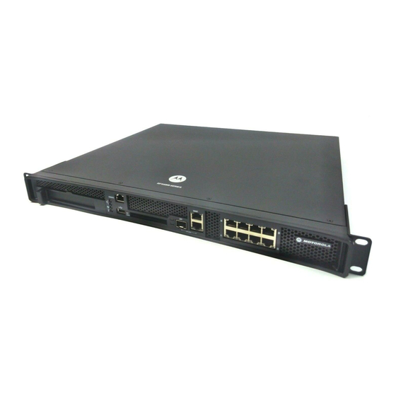
Hardware Setup Hardware Setup Out-of-band PoE enabled gigabit ethernet Console management ports 1, 3, 5, 7 ExpressCard Ports 2, 4, 6, 8 UPLINK 4.1 Cabling Information Out-of-band management port Console connector Gigabit Ethernet RJ-45 connectors with per-port LEDs and PoE UPLINK ExpressCard port... -
Page 16: Hardware Setup
The RFS6010 RF Switch has nine RJ-45 Gigabit Ethernet ports and one Gigabit SFP (fiber optic) port. Using the RJ-45 ports requires connecting a Category-6 Ethernet cable to the port. Each of the eight ports support Power-over-Ethernet. To use the Gigabit SFP port, first install the SFP Module (Motorola Part Number: Fiber-3000-1S-WWR). - Page 17 Hardware Setup 4.2.1 Installing the Gigabit Ethernet SFP Open the bail on the transceiver. Open bail to insert or remove SFP transceiver Insert the SFP transceiver into the corresponding port on the switch. Once the SFP transceiver is properly seated in the port, close the bail to lock the transceiver in place.
- Page 18 Hardware Setup Insert the fiber optic cables into the installed transceiver.
-
Page 19: Connecting Usb Devices
Wait a few seconds for the drive to be recognized by the switch. Follow the instructions in the Motorola RF Switch System Reference or CLI Reference for more information on accessing USB storage devices from the switch for file transfers or firmware updates. -
Page 20: Rack Mount Instructions
Hardware Setup 4.4 Rack Mount Instructions To install the RFS6000 Series RF Switch in a rack: The rack mounting brackets are installed at the factory. No additional steps are needed. Attach the brackets to the rack using screws appropriate for your rack’s mounting holes. - Page 21 Hardware Setup 4.5 RFS6000 Series RF Switch Console Port Setup To add the RFS6000 Series RF Switch to the network and prepare it for initial configuration: Using the supplied console cable (pictured below), connect the RFS6000 Series RF Switch serial port to an RS-232 (DB-9) serial port on a separate computer (the “configuration computer”).
- Page 22 AC inlet Rack mount bracket Plug an approved AC power cord into the power connector at the back of the RFS6000 Series RF Switch. Plug the cord into a standard AC outlet with a voltage range of 100 to 240 VAC.
-
Page 23: Verifying The Installation
• After the software has finished initializing, the System 1 LED will be lit solid green and the bottom System 2 LED will be off. The RFS6000 Series RF Switch is ready to be configured, as described in the Motorola RF Switch System Reference. -
Page 24: Regulatory Information
This regulatory section applies to the RFS-6010. For more information refer to section 6, Part Numbers, Support, and Sales. All Motorola devices are designed to be compliant with rules and regulations in locations they are sold and will be labeled as required. -
Page 25: Regulatory Information
Statement of Compliance Motorola hereby declares that this device is in compliance with all the applicable Directives, 2004/108/EC, 2006/95/EC. A Declaration of Conformity may be obtained from http://www2.symbol.com/doc/... - Page 26 Regulatory Information Waste Electrical and Electronic Equipment (WEEE) English: For EU Customers: All products at the end of their life must be returned to Symbol for recycling. For information on how to return product, please go to: http://www.symbol.com/environmental_compliance. Dansk: Til kunder i EU: Alle produkter skal returneres til Symbol til recirkulering, når de er udtjent.
- Page 27 Regulatory Information Italiano: per i clienti dell'UE: tutti i prodotti che sono giunti al termine del rispettivo ciclo di vita devono essere restituiti a Symbol al fine di consentirne il riciclaggio. Per informazioni sulle modalità di restituzione, visitare il seguente sito Web: http://www.symbol.com/ environmental_compliance.
-
Page 28: Part Numbers, Support, And Sales
• Model number or product name • Software type and version number Motorola responds to calls by email, telephone or fax within the time limits set forth in support agreements. If you purchased your Enterprise Mobility business product from a Motorola business partner, contact that business partner for support. -
Page 29: End-User License Agreement
ANOTHER PERSON OR ANY OTHER LEGAL ENTITY, YOU REPRESENT AND WARRANT THAT YOU HAVE THE AUTHORITY TO BIND THAT COMPANY, PERSON OR ENTITY. LICENSE GRANT. Subject to the terms of this Agreement, Motorola, Inc. and/or its subsidiaries ("Licensor") hereby grants Licensee a limited, personal, non-sublicensable, non-transferable, nonexclusive license to use the software that Licensee is about to download or install and the documentation that accompanies it (collectively, the "Software") - Page 30 Motorola, Inc. End-User License Agreement interrupt, destroy or limit the functionality of any computer software or hardware or telecommunications equipment. Licensee, not Licensor, remains solely responsible for all Content that Licensee uploads, posts, e-mails, transmits, or otherwise disseminates using, or in connection with, the Software.
- Page 31 "Restricted Rights" as provided for in FAR, 48 CFR 52.227-14 (JUNE 1987) or DFAR, 48 CFR 252.227- 7013 (OCT 1988), as applicable. The "Manufacturer" for purposes of these regulations is Motorola, Inc., One Motorola Plaza, Holtsville, NY 11742.
- Page 32 Motorola, Inc. End-User License Agreement...
- Page 33 Motorola, Inc. End-User License Agreement...
- Page 34 Motorola, Inc. End-User License Agreement...
- Page 35 Motorola, Inc. End-User License Agreement...
- Page 36 MOTOROLA INC. 1303 E. ALGONQUIN ROAD SCHAUMBURG, IL 60196 http://www.motorola.com 72-109855-01 Revision A March 2008...
Need help?
Do you have a question about the RFS6000 Series and is the answer not in the manual?
Questions and answers