Table of Contents
Advertisement
Quick Links
© Copyright 1993, 1994, 1995
EVERTZ MICROSYSTEMS LTD.
5288 John Lucas Drive, Burlington, Ontario, Canada, L7L 5Z9
Phone:
905-335-3700
Internet:
Tech Support: eng@evertz.com
Sales:
Web Page:
Revision 2.1, May 1996
KEY-LOG and KeyPost are trademarks of Evertz Microsystems
KEYKODE is a trademark of Eastman Kodak
DigiSync® is a registered trademark of the National Film Board of Canada
The material contained in this manual consists of information that is the property of Evertz Microsystems and is
intended solely for the use of purchasers of the 4025 Film Footage Encoder. Evertz Microsystems expressly
prohibits the use of this manual for any purpose other than the operation of the 4025.
All rights reserved. No part of this publication may be reproduced without the express written permission of Evertz
Microsystems Ltd.
Copies of this guide can be ordered from your Evertz products dealer or from Evertz
Microsystems.
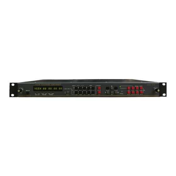
Model 4025
Film Footage Encoder
Instruction Manual
1996
,
Fax:
sales@evertz.com
http://www.evertz.com
905-335-3573
Advertisement
Table of Contents

Related Manuals for evertz 4025


Summary of Contents for evertz 4025
- Page 1 DigiSync® is a registered trademark of the National Film Board of Canada The material contained in this manual consists of information that is the property of Evertz Microsystems and is intended solely for the use of purchasers of the 4025 Film Footage Encoder. Evertz Microsystems expressly prohibits the use of this manual for any purpose other than the operation of the 4025.
- Page 2 WARNING Changes or Modifications not expressly approved by Evertz Microsystems Ltd. could void the user’s authority to operate the equipment. Use of unshielded plugs or cables may cause radiation interference. Properly shielded interface cables with the shield connected to the chassis ground of the device must be used.
- Page 3 Model 4025 Film Footage Encoder Manual REVISION HISTORY REVISION DESCRIPTION DATE Original issue - preliminary release Dec 92 Updated with technical information and drawings Feb 93 Change sheet 1.1-1 added May 93 Change sheet 1.1-2 added for units fitted with ARRI-KIT May 93 Change sheet 1.1-1 revised for Kodak 5298 film emulsion code...
- Page 4 Model 4025 Film Footage Encoder Manual...
-
Page 5: Table Of Contents
2.1.3. Reader Connectors......................2-2 2.1.4. Character Generator Connectors ..................2-3 2.1.5. Serial I/O Connections....................... 2-3 2.1.6. Power Connections......................2-3 2.2. INSIDE THE 4025: REMOVING THE FRONT PANEL ............... 2-3 2.3. MOUNTING ..........................2-4 2.4. POWER REQUIREMENTS ......................2-4 2.4.1. Selecting the Correct Mains Voltage ................. 2-4 2.4.2. - Page 6 2.12. CONNECTING A FILM BARCODE READER................2-25 2.12.1. Hardware Installation....................2-26 2.12.2. Verifying Communications between the 4025 and the Reader ........ 2-26 2.12.3. Learning the Mechanical Offset Between the Reader Head and the Telecine Gate 2-26 2.12.4. Manual Head Offset Adjustments................2-29 2.12.5.
- Page 7 3.5.3 Selecting the Video Standard of Operation ................ 30 3.5.4 Programming the Head Offset for the KeyKode Reader ............ 31 3.5.5 Compensating for Video path Delays between the telecine and the 4025 ......31 3.5.6 Setting up the White Flag Generator .................. 31 PROGRAMMING THE HARDWARE CONFIGURATION - THE HARDWARE MENU....
- Page 8 3 PERF SOFTWARE........................4-4 4.2.1. Hardware Requirements....................4-4 4.2.2. 3 Perf Numbering....................... 4-4 4.2.3. Setting Up The 4025 To Operate In 3 Perf Mode .............. 4-5 4.2.4. 3 Perf Indicators ........................ 4-5 4.2.5. Manual Entry of KeyKode Numbers .................. 4-6 4.2.6.
- Page 9 6.4. RESETTING THE 4025 TO FACTORY DEFAULTS..............6-14 6.4.1. Resetting The 4025 Using The Toolbox Hardware Menu..........6-14 6.4.2. Resetting The 4025 Using The Engineering Shortcut Keys ..........6-14 6.4.3. Resetting The 4025 Using The DIP Switches..............6-14 6.5. LTC/VITC GENERATOR MODULE CIRCUIT DESCRIPTION ..........6-15...
- Page 10 7.1.3. Aux I/O..........................7-2 7.2. CABLE WIRING DIAGRAMS...................... 7-2 7.2.1. to Evertz 5500 or RIM DigiSync & Cinema Products KeyKode Reader Cable....7-2 7.2.2. to ARRI KeyKode Reader Cable ..................7-3 7.2.3. Rank Cintel MKIIIC Mag Follower Y Cable................ 7-3 7.2.4.
- Page 11 Figure 2-8: Telecine Transfer with Synchronized Audio, and Key-Log Data Logging (Jam syncing to LTC from the master VTR) ................2-9 Figure 2-9: 4025 & 8025 Configuration for 4:2:2 Parallel Digital + VITC Applications ....2-10 Figure 2-10: Rank Cintel Frame Pulse Specification ..............2-16 Figure 2-11: BTS FRID Pulse Specification................
- Page 12 Figure 7-1: Evertz Part WA-C67 ....................7-2 Figure 7-2: 4025 to ARRI Cable....................7-3 Figure 7-3: Rank Cintel MK III to 4025 Bi-phase Cable .............. 7-3 Figure 7-4: Serial I/O to PC Cable ....................7-4 Figure 8-1: Reader Head and Bracket - Top View..............8-2 Figure 8-2: Reader Head and Bracket - Side View..............
- Page 13 Model 4025 Film Footage Encoder Manual 7025 Display / Keypad Component Layout ...................7025-80A 7102 Power Supply Schematic......................7102-31B 7102 Power Supply Component Layout ..................7102-80B TABLE OF CONTENTS...
- Page 14 Model 4025 Film Footage Encoder Manual This page left intentionally blank TABLE OF CONTENTS...
- Page 15 Model 4025 Film Footage Encoder Manual 1. OVERVIEW ............................1-1 1.1. HOW TO USE THIS MANUAL......................1-4 1.2. DEFINITIONS ........................... 1-4 Figures: Figure 1-1: Dailies Transfer Using Keykode ................1-3...
- Page 16 Model 4025 Film Footage Encoder Manual This page left intentionally blank...
- Page 17 (VCG). The VCG is also used as an on screen programming aid to the many operational modes of the Model 4025. The Model 4025 uses the latest state of the art technology, combined with our extra intelligent firmware, to offer you the ultimate in performance, reliability, and adaptability.
- Page 18 4025. KeyKode numbers occur approximately every half foot on the film stock, so the basic numbering of film edge numbers by the 4025 is still driven from the bi-phase input. The bi-phase base numbers are automatically updated from incoming KeyKode, taking into account the mechanical offset between the reader head and the gate, and other delays in the system.
-
Page 19: Overview
General Purpose Input (GPI) closure issued to the 4025. With the aid of a properly wired cable, Key-Log can issue the GPI's to the 4025 on activation of a 'hot key', so the operator has complete control over what material gets logged. -
Page 20: How To Use This Manual
If you are currently an owner of the Evertz 4015 Film footage Encoder, you will find 4015 that much of the installation is similar for the 4025. Items that are of particular not for 4015 users are marked with the following symbol in the margin. - Page 21 GEN LOCK: In order to ensure that the timecode to video relationship is fixed, according to SMPTE/EBU specifications, a video reference must be supplied to the 4025 Film Footage Encoder. Normally, the gen lock signal is the program video out from the telecine, onto which the vertical interval time code (VITC) is being applied.
- Page 22 Model 4025 Film Footage Encoder Manual reference is necessary, even if vertical interval time code is not being used. WHITE FLAG: A white pulse recorded on one or more lines in the vertical interval on the first video field of a new picture. This pulse is normally used on 24 frame per second transfers to NTSC video that will end up on video disc recorders.
- Page 23 2.1.4. Character Generator Connectors..................2-3 2.1.5. Serial I/O Connections ....................... 2-3 2.1.6. Power Connections......................2-3 2.2. INSIDE THE 4025: REMOVING THE FRONT PANEL ..............2-3 2.3. MOUNTING ............................2-4 2.4. POWER REQUIREMENTS ......................2-4 2.4.1. Selecting the Correct Mains Voltage.................. 2-4 2.4.2.
-
Page 24: Figure 2-8: Telecine Transfer With Synchronized Audio, And Key-Log Data Logging
Figure 2-8: Telecine Transfer with Synchronized Audio, and Key-Log Data Logging (Jam syncing to LTC from the master VTR)....................... 2-9 Figure 2-9: 4025 & 8025 Configuration for 4:2:2 Parallel Digital + VITC Applications ....2-10 Figure 2-10: Rank Cintel Frame Pulse Specification ..............2-16... -
Page 25: Installation
4025. 4015 Evertz 4015 users who are upgrading to 4025 units will be familiar with most of the connections. Most of the connections are the same as for the model 4015. Pay particular attention to alerts identified with the symbol shown at the left. -
Page 26: Telecine Connections
Rank Cintel Flying Spot scanners. Connection of a Film frame pulse is required even with PAL video to permit the 4025 to distinguish the difference between the field 1 and field 2 dominant pull downs. For applications such as flatbed editing tables where a frame pulse is not available DIP switch #7 on the 615 card can be set to the CLOSED position. -
Page 27: Character Generator Connectors
AUX I/O: A 9 pin female 'D' connector for connection to an external KeyKode Reader. 2.1.6. Power Connections LINE: The 4025 may be set for either 115v/60 Hz or 230v/50 Hz AC operation. The voltage selector switch is accessible on the rear panel. The line voltage connector contains an integral slow blow fuse (and a spare one). -
Page 28: Mounting
2.3. MOUNTING The 4025 Film Footage Encoder is equipped with rack mounting angles and fits into a standard 19 inch by 1 3/4 inch (483mm x 45mm) rack space. The mounting angles may be removed if rack mounting is not desired. -
Page 29: Sample Configurations
Figure 2-7 shows the typical connection when jam syncing to pre- striped code on the master transfer roll. Figure 2-8 shows the typical connection when synchronizing production audio during the telecine transfer. Figure 2-9 shows the typical connection when using the 4025 with the 8025 Digital VITC inserter. TELECINE MONITOR/4025... -
Page 30: Figure 2-5: Minimum Connections
Model 4025 Film Footage Encoder Manual Figure 2-5: Minimum Connections INSTALLATION Page 2-6... -
Page 31: Figure 2-6: Basic Telecine Video Transfer
Model 4025 Film Footage Encoder Manual TELECINE FROM BARCODE COMPUTER READER HEAD KEY CODE READER KJ123456 2345+00 model 5500 SERIAL DATA SERIAL DATA FRAME BIPHASE PULSE VIDEO CHAR. GEN GENERATOR READER FUSE LTC OUT LTC IN FILM FRAME 115V: VITC IN .25 A... -
Page 32: Figure 2-7: Telecine Transfer To Pre-Striped Tape (Jam)
Model 4025 Film Footage Encoder Manual TELECINE FROM BARCODE COMPUTER READER HEAD KEY CODE READER KJ123456 2345+00 model 5500 SERIAL DATA SERIAL DATA FRAME BIPHASE PULSE VIDEO CHAR. GEN GENERATOR READER FUSE LTC OUT LTC IN FILM FRAME 115V: VITC IN .25 A... - Page 33 Model 4025 Film Footage Encoder Manual TELECINE FROM BARCODE COMPUTER READER HEAD KEY CODE READER KJ123456 2345+00 model 5500 SERIAL DATA SERIAL DATA FRAME BIPHASE PULSE VIDEO CHAR. GEN GENERATOR READER FUSE LTC OUT LTC IN FILM FRAME 115V: VITC IN .25 A...
-
Page 34: Figure 2-9: 4025 & 8025 Configuration For 4:2:2 Parallel Digital + Vitc Applications
DIGITAL IN 115V: PARALLEL KEY INPUTS REF SYNC SERIAL .25 A 230V: FILL .125 A SERIAL PARALLEL SERIAL PARALLEL DIGITAL VTR DIGITAL VIDEO +VITC Figure 2-9: 4025 & 8025 Configuration for 4:2:2 Parallel Digital + VITC Applications INSTALLATION Page 2-10... -
Page 35: Connecting The Video Reference
If the 4025 is in NTSC mode and PAL video is connected, the NTSC GENLCK LED will blink. If it is in PAL mode and NTSC video is connected, the PAL GENLCK LED will blink. -
Page 36: Connecting The Ltc Generator
(See section 3.9.1) 2.8. CONNECTING THE TIMECODE READERS The 4025 LTC/VITC time code reader is used to Jam sync the generator to off tape time code when assemble edits are being performed or when INSTALLATION... -
Page 37: Connecting The Vitc Reader
In addition to providing field accurate burn-ins of the video and audio time codes film edge numbers and absolute frames, the character inserter provides Format menus, to help configure the 4025 to your operational requirements quickly. The character generator is also used to display system diagnostics, which help users to quickly locate problems with the installation. -
Page 38: Connecting A Rank Cintel Telecine
These TTL level pulses usually come at a rate of 10 pulses per film frame. The 4025 can also accommodate tach rates of 1, 2 or 5 pulses per frame. For best results use the highest bi-phase rate possible. -
Page 39: Rank Cintel Film Frame Pulse
The 4025 uses the film frame pulse to lock its timecode output to the correct telecine pulldown sequence during the transfer. -
Page 40: Rank Cintel Mkiiic Digiscan 3
Model 4025 Film Footage Encoder Manual This signal may be applied to either of the pair of connectors on the 4025 labelled “FILM FRAME”. The loop-thru is provided to allow connections to other devices that may need this signal. This is NOT a video level signal. Do NOT terminate this signal. -
Page 41: Rank Cintel Ursa
3 & 7 of the 9 pin parallel I/O D connector. Connect ground to pin 6 on the rear of the 4025. Retain the separate shielding of each signal up to the 4025 in order to prevent cross-coupling which can adversely affect the bi- phase reliability. -
Page 42: Connecting A Rank Cintel Ursa Gold
3 & 7 of the 9 pin parallel I/O D connector. Connect ground to pin 6 on the rear of the 4025. Retain the separate shielding of each signal up to the 4025 in order to prevent cross-coupling which can adversely affect the bi- phase reliability. - Page 43 When the telecine achieves locked PLAY speed, the telecine FRAME and LOCK LEDs on the 4025 front panel should be on and there should be a ‘+’ between the footage and frames in the character generator.
-
Page 44: Connecting A Bts Telecine
These TTL level pulses usually come at a rate of 10 pulses per film frame. The 4025 can also accommodate tach rates of 1, 2 or 5 pulses per frame. For best results use the highest bi-phase rate possible. -
Page 45: Bts Film Frame Pulse
Model 4025 Film Footage Encoder Manual To minimize the effects of cross coupling and noise on the bi-phase signals, which can affect the counting reliability of the 4025, you use a cable which provides separate shields for each phase of the bi-phase signal. -
Page 46: Bts Fdl-60
9 pin parallel I/O connector of the 4025 respectively. Connect ground (pin 7 on the telecine connector to pin 6 on the 4025 connector. Note that the pulse output should be set to 10 pulses per film frame by proper selection of the jumper on the sprocket Pulse card in the telecine (FY806 or FM735 card). -
Page 47: Bts Quadra
Connect the PRESTOP signal (Pin 3 on the WETGATE connector of the Quadra) to PIN 4 of the 4025 PARALLEL connector. You will also need to remove the cover of the 4025 and set Jumper J37 on the 7006 I/O board to the 4IN position. - Page 48 When the telecine achieves locked PLAY speed, the telecine FRAME and LOCK LEDs on the 4025 front panel should be on and there should be a ‘+’ between the footage and frames in the character generator.
-
Page 49: Connecting A Film Barcode Reader
KeyKode reader. Most of the KeyKode readers use RS-232-C level signals to communicate with the 4025. 4015 Evertz 4015 users note that this is NOT the same connector used to connect the KeyKode readers to the 4015 Film Footage Encoder. INSTALLATION... -
Page 50: Verifying Communications Between The 4025 And The Reader
2.12.2. Verifying Communications between the 4025 and the Reader Once the KeyKode reader has been installed on the telecine, and connected properly to the 4025, you are ready to verify that the reader is reading properly, and that the two units are communicating. - Page 51 To enable Engineering mode, turn DIP switch #8 on the 631 module (right hand card inside the 4025) to the Closed (On) position. TIMECODE...
-
Page 52: Manual Head Offset Adjustments
Model 4025 Film Footage Encoder Manual When you press SHIFT + SELECT a second screen appears that allows you to proceed with manual adjustments or automatic learning. TIMECODE FILM CONFIG HEAD OFFSET ADJUSTMENT SELECT TO LEARN SHIFT + SELECT TO ADJUST... -
Page 53: Automatic Head Offset Learning
(“PERF type”) may cause errors to be introduced into the footage numbers. 4015 The 4025's PERF numbering scheme has been changed from the 4015 so that it conforms to the industry standard head to tails orientation. The on screen graphic display accurately shows the KeyKode perf orientation so as to avoid confusion. - Page 54 Make sure that the reference frame is properly framed in the gate. Press SELECT to proceed. Enter the film edge number of the reference frame into the 4025 using the ENTER and numeric keys. The frame number will be in inverse video when you are in entry mode.
- Page 55 Model 4025 Film Footage Encoder Manual TIMECODE FILM CONFIG REFERENCE FRAME NUMBER 0000+00 ENTER TO CHANGE SELECT TO CONTINUE TIMECODE FILM CONFIG OFFSET LEARN FOR 35 MM 24 FPS ROLL FILM - WAIT FOR LOCK AND KEYKODE Put the telecine into the Play mode. When the telecine achieves stable lock speed, the next screen will appear.
- Page 56 Press the SHIFT + SELECT keys to learn the head offset. The head offset value shown will be automatically recalculated by the 4025, and the whole frame error shown should go to zero. It may be necessary to press the SHIFT + SELECT keys a second time if the initial value of the whole frame error is large.
-
Page 57: Verifying The Accuracy Of The Keykode Numbering
Head offset has been learned correctly. The 4025 maintains separate head offsets for 16 and 35 mm film and for each film transfer rate. Make sure that you check each combination to ensure that your system is fully configured. -
Page 58: Use Of Keykode With Low Tach Rate Flying Spot Telecines
This has the effect of varying the bi-phase to film frame relationship throughout the transfer. In order to track the scantrack position the 4025 keeps track of the bi-phase counts relative to the film frame pulse. When low tach rate telecines are used with their Scantrack turned on, the... -
Page 59: Connecting An External Computer - Data Logging
1 film frame. The KeyKode number that the 4025 jams to when the telecine is first put into Play is correct because the Rank's Scantrack offset is zero when started. During the transfer, it is normal for the KeyKode status ERR display to show ±1. -
Page 60: Connecting The Parallel Remote Controls
4025 that the film is centered in the gate. Momentarily ground this input to ‘centre’ the 4025’s film frame boundary reference. See section 3.10.8 for a full description of centering. -
Page 61: Generator Run /Zero Reference Frame And Dlo Gpi
+5 volts and may be grounded to pin 6. Jumpers J26, J27, J28 and J29 located on the 4025 I/O board (near the SERIAL I/O connector) must be in the RS232 position (factory default) for the remote inputs to be active. - Page 62 Model 4025 Film Footage Encoder Manual This page left intentionally blank...
- Page 63 3.5.3. Selecting the Video Standard of Operation................. 30 3.5.4. Programming the Head Offset for the KeyKode Reader............. 31 3.5.5. Compensating for Video path Delays between the telecine and the 4025 ......31 3.5.6. Setting up the White Flag Generator .................. 31 3.6.
- Page 64 3.9.5. Selecting the Generator Drop Frame Mode (NTSC only) ........... 42 3.9.6. Setting up the 4025 for Jam Sync to the VTR Time Code ..........42 3.9.7. Selecting the Lines to Record VITC on - (Except 3 Line VITC Standard)......43 3.9.8.
- Page 65 Figure 3-6: Register Status Indicators ..................15 Figure 3-7: Function Status Indicators ..................17 Figure 3-8: Overview of the 4025 Format Menu System ............. 19 Figure 3-9: Overview of the Toolbox Menu.................. 20 Figure 3-10: How the Time and KeyKode numbers are encoded in various Time Code Modes........................
- Page 66 Model 4025 Film Footage Encoder Manual This page left intentionally blank...
-
Page 67: How To Operate The Film Footage Encoder
Model 4025 Film Footage Encoder Manual HOW TO OPERATE THE FILM FOOTAGE ENCODER AN OVERVIEW OF KEY AND DISPLAY FUNCTIONS OPERATION Page 1... - Page 68 Model 4025 Film Footage Encoder Manual OPERATION Page 2...
-
Page 69: The Display Push-Button Group
The keypad is divided into four logical groupings to control the front panel display, the data entry modes, the on screen format system, and the frequently used functions of the 4025. When the SHIFT key is held down, the meanings of many of the keys are modified, gaining quick access to a wider variety of functions. - Page 70 Model 4025 Film Footage Encoder Manual OPERATION Page 4...
- Page 71 TIME / UB key. In their normal functions, these keys control only what data is being displayed on the front panel, (they do not change the operational modes of the 4025). The leftmost characters of the front panel display are used to prompt which data is being displayed. When the ENTER key is...
-
Page 72: Data Entry Push-Button Group
Pressing the SHIFT key and the numeric keys 0 to 5 will enter the corresponding hexadecimal values A to F. When the 4025 is in data entry mode, the left characters of the display blink, indicating that the numeric keys are active. - Page 73 Model 4025 Film Footage Encoder Manual The format key group consists of the FORMAT, SELECT and keys and is used to navigate the format menu system. When not in the format menus, the arrow keys are used for character positioning.
-
Page 74: The Function Push-Button Group
Model 4025 Film Footage Encoder Manual 3.1.4 The Function Push-button Group OPERATION Page 8... - Page 75 Model 4025 Film Footage Encoder Manual OPERATION Page 9...
- Page 76 Figure 0-4: Function Pushbutton Group The function key group consists of eight keys and is used for controlling frequently used functions of the 4025. These keys are coloured RED to indicate that they affect the operation of the unit and should be used with caution.
-
Page 77: Overview Of The Shifted Key Functions
Toggles RAM VIEW ENTRY MODE when RAM VIEW is enables. 3.1.6 An Overview of the Status Indicators There are 15 status indicators located on the front panel which show operational status of the 4025 at a glance. OPERATION Page 11... - Page 78 Model 4025 Film Footage Encoder Manual OPERATION Page 12...
- Page 79 FRAME Indicates that the 4025 has detected the presence of a valid film frame pulse from the telecine. If the 4025 is not set for the same video standard and film transfer rate as the incoming film frame pulse, this LED will be OFF.
- Page 80 Model 4025 Film Footage Encoder Manual OPERATION Page 14...
- Page 81 This usually indicates that the head offset has not been learned, or that KK JAM is set to NEVER. The KKODE LED will also blink when a keykode discontinuity is detected by the 4025. RDR 1 Indicates that Reader 1 is reading valid time code.
- Page 82 Model 4025 Film Footage Encoder Manual OPERATION Page 16...
-
Page 83: Format Menu - Overview
25 FPS. FORMAT MENU - OVERVIEW The key to the operational flexibility of the 4025 Film Footage Encoder lies in the powerful Format menu system. . The format menu uses the built in character generator and provides an quick, intuitive method of configuring 4025 Film Footage Encoder, guiding you to the correct setup for your application. - Page 84 Model 4025 Film Footage Encoder Manual modes such as KeyKode Jam, film type, film transfer rate, etc. CONFIG drop down menu is used to configure miscellaneous items such as video standard, character size and style, KeyKode head offset, video path delays, etc.
-
Page 85: Engineering Tool Box Menu
This menu should be used by advanced users only, as improper use can overwrite KeyKode Head offsets and other user setups. The 4025 Toolbox menu system consists of three drop down menus. The titles of each of the drop down menus are shown on the top line of the character display. - Page 86 Model 4025 Film Footage Encoder Manual FRONT PANEL PARAMETERS DEBUG BRIGHTNESS = 2 PLAY WINDOW KK STATS VIEW TO ADJUST KK PLAY RAM TEST WINDOW = 00 TO ACTIVATE RAM TO ADJUST RAM VIEW TEST SHUTTLE WINDOW PRESS THE KK SHUTTLE...
-
Page 87: Programming The Basic Operational Modes - The Timecode Menu
PROGRAMMING THE BASIC OPERATIONAL MODES - THE TIMECODE MENU The TIMECODE menu is used to configure the basic operational modes of the 4025 Film Footage Encoder such as selecting what information is put into the time and user bits, setting VITC line numbers for the generator, assigning the LTC and VITC readers, etc. -
Page 88: Figure 3-10: How The Time And Keykode Numbers Are Encoded In Various Time Code Modes
Model 4025 Film Footage Encoder Manual line VITC standard for encoding Film information. This standard has been agreed upon by a number of manufacturers and uses 2 blocks of 3 lines each to encode the information. Figure 0-10 gives a summary of the first six GEN ASSIGN modes and their meanings. - Page 89 KeyKode information. Select 3 LINE VITC STD to encode the time and keykode information using the 3 line VITC standard which Evertz has developed along with other manufacturers. The encoded data is contained in a block of three consecutive lines of the vertical interval.
-
Page 90: Selecting The Line Numbers To Record Vitc On
Model 4025 Film Footage Encoder Manual When you are using the 3 Line VITC STD generator assignment the operation of some of the other menu items changes as follows 1. The VITC LINES are set using the VITC1 LINES menu item. -
Page 91: Selecting The Reading Mode Of The Ltc/Vitc Reader
Model 4025 Film Footage Encoder Manual that the generator drop frame mode is set to be the same as the incoming reader data’s drop frame mode. 3.3.4 Selecting the Reading Mode of the LTC/VITC Reader The LTC and VITC readers may be operated as separate readers and assigned to Reader 1 or Reader 2, or, they may be operated as one Auto reader which reads both LTC and VITC. - Page 92 (e.g. ACMAID number) than the latent edge number must be used. When the 4025 is in the Ink number mode, you can only select KKJAM NEVER. To select one of the other KKJAM modes you must first take the 4025 out of the Ink number mode by entering a manufacturer’s code other...
-
Page 93: Selecting How The Keykode Prefix Is Displayed In The Vcg
4025 are being updated from the barcodes, or only from the telecine bi-phase. With INFO CHECK the 4025 will change the font of the Key info part of the film edge number window when 4025 detects that the barcode information is missing, and the edge numbers are being updated only by the telecine bi-phase. -
Page 94: Selecting The Film Transfer Rate
Some telecines continue the frame pulse in an unbroken sequence even when they are in still or shuttle modes. When used with these telecines, the 4025 can be configured for AUTO rate detect. Changes in transfer rates by the telecine operator are automatically detected when the telecine is in still. -
Page 95: Selecting The Encoding Format Of The Film Edge Numbers
When using the 4025 with KeyKoded stock 4 DIG FT+FRM format should be used. When using the data logging output of the 4025, 4 DIG FT+FRM format MUST be selected. No data packets will be transmitted to the logging computer in 5,6 or 7 digit formats. -
Page 96: Programming Miscellaneous Items - The Config Menu
4025. The proper video standard setting must be selected in order to obtain a positive gen-lock reference to the 4025. Select AUTO to allow the 4025 to auto detect the standard of the gen-lock video reference. This is the factory default condition. -
Page 97: Programming The Head Offset For The Keykode Reader
4025 VIDEO DELAY Is used to adjust for whole field delays which put the 4025 input video out of sync with the bi-phase and Frame pulse inputs. Delay compensations affect the VITC, LTC and Character Generator outputs. These delays can occur through the use of devices such as noise reducers and encoders. -
Page 98: Programming The Hardware Configuration - The Hardware Menu
See section 2.10.2 or 2.11.2 for information about connecting bi-phase from your telecine. In some early versions of the 4025 firmware DIP Switches #3 & 4 on the 615 module were used to set the bi-phase rate. They are used for other purposes now and should be set in accordance with the figure 6-6 in section 6.3.7. -
Page 99: Selecting The Correct Frame Pulse Handling
Rank Cintel URSA GOLD telecines. In the IGNORED mode the 4025 ignores the FILM FRAME input and the Frame LED on the 4025 front panel will be ON all the time. This mode is useful in situations where the film transfer... -
Page 100: Resetting The 4025 To Factory Defaults
1 of a video frame. 2. The pulldown for 24 FPS NTSC transfers will be random and the 4025 will track the film frames to within +/- 1 frame of accuracy. In flat bed editing tables and other devices that... -
Page 101: Controlling The Keykode Jam When The Telecine Is In Shuttle Speeds
Model 4025 Film Footage Encoder Manual In some early versions of the 4025 firmware DIP Switch #5 on the 615 module was used to set the PLAY WINDOW. It is used for other purposes now and should be set in accordance with the chart in Figure 6-6. -
Page 102: Setting The Full Stop Time
( If auto centering is turned ON). The factory default setting of 1:00 means that the 4025 will detect FULL STOP when the film is stationary for at least 1 second. Use the &... -
Page 103: Configuring The Operation Of The Vcg Remote Control Inputs
Model 4025 Film Footage Encoder Manual Select RUN when you want the generator to free run when there is no incoming Reader code. When the reader code resumes, the generator will re-jam to the incoming code. Using this mode will allow the user to repair large dropouts in the incoming code. -
Page 104: Turning On Diagnostics Aids - The Debug Menu
The secondary VITC generator is used to encode the full KeyKode edge number including frames in certain modes. The 4025 also supports encoding the data in VITC according to the 3 Line VITC Evertz has developed with other manufacturers. Both the VITC 2 line... -
Page 105: Understanding Time Code 'Add One' Compensation- How It Affects The Accuracy Of The Timecode And Burn-Ins
Model 4025 Film Footage Encoder Manual The 4025 also contains an LTC/VITC reader which can be operated as two separate readers (known as Reader 1 and Reader 2), or, they may be operated as one Auto reader which reads both LTC and VITC. In this case, the Auto reader is assigned to Reader 1 and Reader 2 is turned off. -
Page 106: Configuring The Time Code Operating Modes
Model 4025 Film Footage Encoder Manual Record VITC from the 4025 onto all your transfer tapes, even if the client does not specify them specifically. When recording timecode from the 4025, the timecode generator in your VTR should either be turned off, or set to an 'external direct' mode. -
Page 107: How To Set The Generator User Bits
Model 4025 Film Footage Encoder Manual entry mode is active, and the dual functioned keys are now changed to their numeric values. If you want to re-enter this time press the ENTER key to complete the data entry into the generator time. -
Page 108: Selecting The Generator Drop Frame Mode (Ntsc Only)
VTR’s time code is to use the internal time code generator in the VTR to generate continuous LTC, and have the 4025 jam to it. The VITC from the 4025 has encoded film numbers and should be recorded on the VTR... -
Page 109: Selecting The Lines To Record Vitc On - (Except 3 Line Vitc Standard)
(See section 3.9.1 for information about the use of your VTR’s time code generator with film edge numbers.) Audio time code may be connected to the 4025’s VITC reader with the use of an LTC to VITC translator such as the Evertz 621-LTR. -
Page 110: Selecting The Lines To Record Vitc On - (3 Line Vitc Standard)
Model 4025 Film Footage Encoder Manual It is recommended that two non-adjacent lines be used, however adjacent lines and a single line (selected when both lines are the same) are permitted. 3.9.8 Selecting the Lines to Record VITC on - (3 Line VITC Standard) When the generator assignment is set to 3 LINE VITC STD, two blocks of 3 lines are encoded. - Page 111 The number of prefix digits permitted is dependent on the maximum footage number that is selected. (See section 3.10.7.) By utilizing a compressed binary format, (EVERTZ mode) up to 7 digits of feet plus frames can be encoded, along with the pulldown information, however, special decoding routines in the time code readers will be required to recover this information and display it as decimal digits.
-
Page 112: 1Configuring The Film Edge Number Operating Modes
The ENTER and CLR keys are used in conjunction with the numeric keys to set the film edge codes. The 4025 is fitted with an interface for connection to an external KeyKode reader. These readers can automatically read the film edge codes from KeyKoded stock and the 4025 can automatically place them into the user bits. -
Page 113: 3Entering Edge Code Prefixes Manually
4025. Note that if the KK JAM mode of the 4025 is set to ONCE, PLAY, or ALWAYS, the next valid data from the KeyKode reader will overwrite the data that was manually entered from the front panel. -
Page 114: 4Acmaid Number Entry
3.10.4 ACMAID Number Entry When KeyKode Jam is turned off, the 4025 edge code registers may be used to hold ACMAID Ink numbers in place of the KeyKode numbers in the character inserter and on the front panel display. - Page 115 NEVER. Otherwise, incoming KeyKode will overwrite the manually entered Ink Number. You must now take the 4025 out of Ink number mode (by manually entering a keykode number with manufacturer other than ‘I’ (See section 3.10.3) before you can set the KKJAM menu item back to one of the other settings.
-
Page 116: 5Selecting The Film Type
Digits that are not used for footage numbers are utilized for the prefix number. Select EVERTZ if you want to use binary encoding to compress more data into the available space. When EVERTZ style is used, 7 digits of edge number information plus frames will be placed into the user bits. -
Page 117: 7Selecting The Maximum Footage Count
When using KeyKoded film stock, the 4025 should be set for the 4 DIG FT + FRM format. 3.10.8 Centering the 4025's Framing Reference... -
Page 118: 9Setting The Film Transfer Rate
(See section 3.11.1 for information on selecting the KK JAM mode.) Pin 5 on the parallel I/O connector on the 4025 rear panel may be used as a centering input. Momentarily close this input to ground and release it when the film is properly still framed in the gate. -
Page 119: Operating The 4025 With Barcoded Film Stock
3.10.10 Using the Parallel Remote Control to select Film Control Modes The 4025 is fitted with a nine pin sub miniature 'D' connector for connection to the telecine. Three pins on the remote control connector may be connected to tallies from the telecine, or to external toggle switches, to program the film type and transfer rate. -
Page 120: 1Selecting When The Barcode Numbers Update The Edge Number Information
The decoder receives these electronic signals from the pickup head, and sends the decoded KeyKode number via a serial link to the 4025. The 4025 Film Footage Encoder automatically 'jams' the edge numbers into the time code user bits or the secondary VITC. - Page 121 When the 4025 is in the Ink number mode, you can only select KKJAM NEVER. To select one of the other KKJ modes you must first take the 4025 out of the Ink number mode by entering a manufacturer’s code other than I.
-
Page 122: 2How To Verify That Your Keykode Is Updating The Edge Numbers
FORMAT or CLR keys to exit the format menu, or press the SELECT key to return to the FILM drop down menu. With KEYINFO CHECK the 4025 will change the font of the Key info part of the film edge number window when 4025 detects that the barcode information is missing, and the edge numbers are being updated only by the telecine bi-phase. - Page 123 Model 4025 Film Footage Encoder Manual Evertz 4015 users note: The 4025's PERF numbering scheme has been 4015 changed from the 4015 so that it conforms to the industry standard head to tails orientation. The on screen graphic display in the Head offset learning procedure accurately shows the KeyKode perf orientation so as to avoid confusion.
-
Page 124: Character Generator Controls
Model 4025 Film Footage Encoder Manual When the KKODE JAM mode is set to ALWAYS, the error should be 00 when the telecine is in Play, and the film has continuous edge numbers. It will be non-zero momentarily when a splice is encountered. When the telecine is in shuttle, non-zero values are normal. -
Page 125: 2Positioning The Overall Character Display
Press the MODE key one more time or press the CLR key to exit the VCG window select mode. The 4025 can position the characters in the vertical interval of the picture, causing them to 'disappear' or to overwrite the VITC. Caution should be used when placing the characters in the vertical interval. -
Page 126: Vcg Drop Frame Indicator (Ntsc Only)
Model 4025 Film Footage Encoder Manual access the Format menu. Using the & keys drop down the CONFIG menu. Use the & keys to highlight the CHAR STYLE menu item and press the SELECT key to show the Character style sub menu. -
Page 127: 7Vcg Film Sequence Lock Indicator
When film edge codes are displayed, a plus sign (+) is used between the feet and frame numbers to indicate when the telecine has achieved a stable play speed and the 4025 has properly locked onto the transfer sequence. 3.12.8 Counting Sequence Error Indicator... - Page 128 Model 4025 Film Footage Encoder Manual See section 3.7.8 for information on how to configure the VCG remote control inputs. The chart below summarizes the operation of the VCG remote control inputs. An X on the chart indicates that this action is ignored.
- Page 129 Model 4025 Film Footage Encoder Manual Input Name Action Software Toolbox Menu Setting TOGGLE EDGE EDGE LEVEL Master VCG Master Toggle Master On Master Off Master Off Master Off Master On High Master On Generator time Gen Tm Toggle Gen Tm On...
- Page 130 Model 4025 Film Footage Encoder Manual This page left intentionally blank...
- Page 131 4.2. 3 PERF SOFTWARE........................4-4 4.2.1. Hardware Requirements ....................4-4 4.2.2. 3 Perf Numbering....................... 4-4 4.2.3. Setting Up The 4025 To Operate In 3 Perf Mode .............. 4-5 4.2.4. 3 Perf Indicators......................... 4-5 4.2.5. Manual Entry of KeyKode Numbers................... 4-6 4.2.6.
- Page 132 Model 4025 Film Footage Encoder Manual This page left intentionally blank...
-
Page 133: Optional Software
The incoming code is assumed to be at the same speed as the film transfer rate setting of the 4025. This means for films transferred at 25 frames per second, that the timecode frames will be numbered from 0 to 24, etc. (i.e. film was shot at 25 FPS) 4.1.3. -
Page 134: Additional Arri Code Status Displays
DEBUG drop down menu and the KK STATS item. Turn KK STATS ON. When the 4025 is operating in one of the ARRI modes, the KK STATS will contain an additional line, known as the ARRI STATS, which is necessary to determine the accuracy of the installation. -
Page 135: Setting The Head Offset
Toolbox) and put the telecine into play. The AERR value should be either 0, 1, or -1. Press the OFFSET key on the 4025 front panel to display the ARRI OFFSET register. Press the vertical arrow keys (", #) while holding down the SHIFT key to trim the ARRI OFFSET register. -
Page 136: Bit Vs. 112 Bit Reading
Model 4025 Film Footage Encoder Manual 4.1.6. Bit vs. 112 Bit reading The 611 LTC reader in the 4025 needs to be specifically programmed for reading either 80 bit (form B) or 112 bit (form C) type code. To do this, there are two Hot Keys made available. -
Page 137: Setting Up The 4025 To Operate In 3 Perf Mode
A new menu item has been added to the FILM TYPE menu item. FILM TYPE 35MM 16 FR/FT Select 35MM 3 PERF to enable 3 perf operation of the 4025. Select 35MM 35MM 3 PERF 16 FR/FT for 4 perf operation. -
Page 138: Manual Entry Of Keykode Numbers
Before proceeding with the head offset learning, you should verify the basic accuracy of the bi-phase based numbers by performing the procedure outlined in the 4025 manual section 2.10.1 for a Rank Telecine or section 2.11.1 for a BTS telecine. - Page 139 Model 4025 Film Footage Encoder Manual TIMECODE FILM CONFIG NTSC HEAD OFFSET SUMMARY 35 MM 24 FPS 0820 41 FRM) 35 MM 30 FPS 0840 42 FRM) 16 MM 24 FPS NONE 16 MM 30 FPS NONE 3PERF 24 FPS...
- Page 140 When the Head offset learning is complete, verify the accuracy of the system by performing the verification tests as outlined in section 2.12.6 of the 4025 manual. When examining the video tape, make sure that you check the numbering for three consecutive feet of film, to ensure that the 4025 is properly identifying the short and long feet.
- Page 141 Model 4025 Film Footage Encoder Manual 5. SYSTEM DIAGNOSTICS ........................5-1 5.1. HELP MESSAGES........................... 5-2 5.1.1. General Messages......................5-2 5.1.2. Telecine Related Messages....................5-2 5.1.3. Counting Sequence Problems ................... 5-3 5.1.4. Timecode Problems ......................5-3 5.1.5. Improper Setups ........................ 5-4 5.1.6.
- Page 142 Model 4025 Film Footage Encoder Manual This page left intentionally blank...
-
Page 143: System Diagnostics
A HELP screen with the latest message for each of the modules in the 4025 is displayed on the character inserter when the HELP key is pressed. (This function is not available from any format menu screen.) These messages are designed to give the user additional explanations about system level problems. -
Page 144: Help Messages
Model 4025 Film Footage Encoder Manual 5.1. HELP MESSAGES General Messages NO NEW PROBLEMS Indicates the 615 message has been reset and no further problems have been detected. GENLOCK MISSING Video is missing from PGM IN, (GENLOCK LED on front panel is actually the video reference for the 613 card). -
Page 145: Counting Sequence Problems
Model 4025 Film Footage Encoder Manual SCANTRACK TOO LARGE The scantrack of the telecine has pushed the bi- phase into the next/previous film frame. This may also be caused by not centering the Film position when new film is loaded on the telecine. (See Section 3.10.8 of the manual). -
Page 146: Improper Setups
Model 4025 Film Footage Encoder Manual Improper Setups 35MM KK MISMATCH 16MM MODE The incoming 35mm KeyKode data does not match the selected 16mm mode. 16MM KK MISMATCH 35MM MODE The incoming 16mm KeyKode data does not match the selected 35mm mode. -
Page 147: Keykode Reader Communications Problems
Model 4025 Film Footage Encoder Manual KeyKode Reader Communications Problems SERIAL: FRAMING/OVERRUN ERR Indicate problems with the serial input data from the KEYKODE reader. These include parity/baud problems and message format SERIAL: PARITY ERROR problems. SERIAL: RECEIVE TIMEOUT 1 SERIAL: RECEIVE TIMEOUT 2... -
Page 148: Keykode Related Messages
Model 4025 Film Footage Encoder Manual KeyKode Related Messages KK JAM: FEET DIFFERS The character generator has updated to the new KK JAM: FRAMES DIFFERS edge number. KK JAM: KEY INFO DIFFERS KK JAM: PREFIX DIFFERS KEYKODE OFF Indicates KK JAM = OFF has been selected. -
Page 149: Ram View
To make use of RAM VIEW you need to have information on which RAM locations to view. This information is available from Evertz technical support staff if you are experiencing difficulties. The RAM VIEW item of the Toolbox DEBUG menu is used to turn on RAM VIEW mode. -
Page 150: Novram Debug
Model 4025 Film Footage Encoder Manual In RAM VIEW - ENTRY mode, the normal operation of the keyboard is suspended. The following keys allow you to change the data being displayed. The Front panel display shows key scan codes, Key Down timer, and the Key Repeat timer "... -
Page 151: Hardware Debug Display Screen
NOVRAM VIEW mode and return to the Toolbox menu. If you have changed any NOVRAM locations it is recommended that you exit the NOVRAM view function by pressing SHIFT + 7 to reinitialize the 4025. 5.6. HARDWARE DEBUG DISPLAY SCREEN The Hardware Debug display screen allows viewing of hardware and operating system related parameters. -
Page 152: Engineering Shortcut Keys
10 pulse per frame biphase outputs. EV-RST contains communications codes for the three processors in the 4025. You may be asked for this value by an Evertz technical support person. EV-SAV contains initial communications codes for the three processors in the 4025. -
Page 153: Front Panel Led Diagnostics
Model 4025 Film Footage Encoder Manual Reserved Freeze VCG updates Display entire small character font Display entire tiny character font HELP Reboot STATUS Hardware Debug Display 5.8. FRONT PANEL LED DIAGNOSTICS To perform a Lamp test of the front panel LED’s: 1. -
Page 154: Module Led Disaster Codes
+ FORMAT keys. A full screen display showing the 631 internal RAM values appears. When you have printed this screen using a video printer, press the SELECT key to display the next screen. When the 4025 has accumulated all the values for the 615 board it will prompt you to PRINT and SELECT. - Page 155 6.3.7. Base Processor Board (631 main board) Jumpers and Switches ........6-12 6.4. RESETTING THE 4025 TO FACTORY DEFAULTS..............6-14 6.4.1. Resetting The 4025 Using The Toolbox Hardware Menu..........6-14 6.4.2. Resetting The 4025 Using The Engineering Shortcut Keys..........6-14 6.4.3.
- Page 156 Model 4025 Film Footage Encoder Manual 6.9.2. Push buttons (7025-31) ....................6-25 Figures Figure 6-1: Inside View ....................... 6-2 Figure 6-2: 7006 I/O Board Default Jumpers ................6-7 Figure 6-3: 6110 LTC Reader Board Default Jumpers ............... 6-8 Figure 6-4: 6111 VITC Reader Sub-module Default Jumpers ............ 6-8 Figure 6-5: 6150 Film Timecode Generator Main Board Default Jumpers .........
-
Page 157: Technical Description
TECHNICAL DESCRIPTION 6.1. OVERVIEW The 4025 is built up from three EV-BLOC 610 series modules. Each of these modules is equipped with high speed serial communications hardware and a powerful protocol designed specifically for the EV-BLOC system, which permits data interchange between different modules within the 4025. -
Page 158: Technical Description
KeyKode reader. The 615 generator is capable of locking to the 2 field RS-170 (4 field PAL) video standards. A high impedance input tapped off the video input loop is used to provide correct framing for the 4025's built-in generator. -
Page 159: Diagnostic Leds
These LEDs are only visible with the front panel removed. 6.2.1. Power Supply LEDs These appear to the extreme left of the interior of the 4025. From front to back they indicate the presence of +8V,-8V and +9V (which runs the 5V regulators for each board). -
Page 160: Generator Leds
2.12.2 for information about connecting the film frame pulse. 6.2.4. Character Inserter LEDs The character inserter module pair is located in the right slot of the 4025. There are two LEDs located at the front of this module. The left LED indicates that the microprocessor is operating and that it is communicating with the reader module. - Page 161 Model 4025 Film Footage Encoder Manual J26, J27, J28, J29 Serial I/O Select 4 Jumpers must all be in the same position RS232 Set serial I/O port for RS232 operation. RS422 Set serial I/O port for RS422 operation. Pin 5 Select...
- Page 162 Model 4025 Film Footage Encoder Manual TECHNICAL DESCRIPTION Page 6-6...
-
Page 163: Ltc Reader Main Board Jumpers
Model 4025 Film Footage Encoder Manual Figure 6-2: 7006 I/O Board Default Jumpers 6.3.2. LTC Reader Main Board Jumpers Selects EV-COM use of MCU serial port Selects EV-COM use of MCU serial port Ext Sync Ex.Sync Connects LTC Sync to Back plane (Req’d for... - Page 164 Model 4025 Film Footage Encoder Manual Figure 6-3: 6110 LTC Reader Board Default Jumpers Figure 6-4: 6111 VITC Reader Sub-module Default Jumpers TECHNICAL DESCRIPTION Page 6-8...
-
Page 165: Film Timecode Generator Main Board Jumpers And Switches
Model 4025 Film Footage Encoder Manual 6.3.4. Film Timecode Generator Main Board Jumpers and Switches Figure 6-5: 6150 Film Timecode Generator Main Board Default Jumpers Future EPROM expansion Future EPROM expansion VITC Video To Rear DC restorer on sub-module is used for VITC... -
Page 166: Support For Telecine Devices That Do Not Have A Frame Pulse Available
To enable the ‘no frame pulse operation’ of the 4025, set DIP Switch # 7 on the 615 card (center module) to the On position. The Frame LED on the 4025 front panel will be ON all the time. -
Page 167: Video Keyer Submodule Jumpers
Model 4025 Film Footage Encoder Manual they change mid-frame, this method will track the film frames to within 1 frame of accuracy. Figure 6-7: 6231 Versions Video Keyer Sub-module Default Jumpers 6.3.6. Video Keyer Submodule Jumpers JPA1 Digital Key Install for Digital Video Out... -
Page 168: Base Processor Board (631 Main Board) Jumpers And Switches
Model 4025 Film Footage Encoder Manual NTSC/PAL Select Auto select of video standard from firmware Forces operation in PAL mode, NTSC VITC bitrate oscillator turned off. Forces operation in NTSC mode, PAL VITC bitrate oscillator turned off. On the 6231A and 6231A1 revisions of the video keyer, jumpers JP8 and JP9 are incorrectly labelled. - Page 169 SHIFT+STATUS). Also visible on Hardware Debug screen ( Invoked by TIME/UB+SHIFT+STATUS). When the Configuring Screen appears, it will remain visible until the CLEAR key is pressed. Pressing SHIFT+CLEAR when the timecode windows are visible sets up the 4025 to capture the next EV-COM reset codes. TECHNICAL DESCRIPTION Page 6-13...
-
Page 170: Resetting The 4025 To Factory Defaults
The FACTORY RESET item of the Toolbox HARDWARE menu is used to reset the 4025 to the factory default parameters. Press SHIFT + ENTER when the sub menu screen is displayed to reset the 4025 to factory defaults. The 4025 will perform a power-on configuration before returning to the normal operating mode. -
Page 171: Ltc/Vitc Generator Module Circuit Description
Push the 615 back in/or power up the 4025. Allow the 4025 to go through the normal power up displays. Check that 615 has reset the keykode head offsets to NONE. With power on reset the 615 DIP switches to original settings. -
Page 172: Adjusting The Ltc Output Level
Model 4025 Film Footage Encoder Manual which is available on the µCLK test point. This frequency is internally divided by 12 in the MCU, resulting in a processor operating frequency of approximately 960 KHz. VIDEO IN LTC OUT VIDEO OUT + VITC... -
Page 173: Telecine Interface Logic (6150-32 & 6150-33)
Parallel I/O connector to quatrature decoder U14. These TTL level pulses usually come at a rate of 10 pulses per film frame. The 4025 can also accommodate tach rates of 1 or 2 pulses per frame. For best results use the highest bi-phase rate possible. -
Page 174: Vitc Generator Interface
FRAME BNC connector on the 4025 rear panel. This active low pulse occurs when a new film frame starts in the video output, while the telecine is in normal play speed. The 4025 uses the film frame pulse to lock its timecode output to the correct telecine pulldown sequence during the transfer. -
Page 175: Ltc/Vitc Reader Circuit Description
Model 4025 Film Footage Encoder Manual 6.6. LTC/VITC READER CIRCUIT DESCRIPTION I/O opt. VIDEO IN LTC IN EV-COM LTC READER Inter-module serial comm. VITC READER (opt.) Figure 6-11: 611 Module Block Diagram The 611 reader is a microcontroller based module functionally divided into the following hardware subsystems: Microcontroller &... -
Page 176: High Speed Ltc Reader (6110-30)
Model 4025 Film Footage Encoder Manual A GENLOCK Field 1 pulse, generated by the 615 module, is received by U18 (jumper J6 must be in the G position) where it is inverted and sent to the MCU. This pulse is used to provide a proper gen-lock reference to the reader, irrespective of the input video to the 611 reader. -
Page 177: Video Character Inserter Circuit Description
Model 4025 Film Footage Encoder Manual At VSYNC, the MCU releases the reset to U7b, enabling the VITC reader circuitry. The first VITC data bit turns on U7a, which releases the reset to CRC detector U1 and U3. A phase locked loop consisting of VCO U13, and U12, U17, and U18, provides an 8 times bit rate clock to divider U11, which generates a series of timing pulses at the VITC bit rate (1.78977... -
Page 178: Microcontroller (6120-32)
Model 4025 Film Footage Encoder Manual main module. Video input buffers and all input/output connectors are contained on a separate I/O module, (7006) into which the 631 module plugs in. The relevant schematic drawings are shown in brackets for each section of the circuit. -
Page 179: Vitc Generator And Character Generator Circuit Description
Once per field, the MCU loads the VITC bit pattern for a particular line into static RAM U9. It is thus possible for the 4025 to generate different VITC data for individual video lines. In practice, the 4025 will generate one line pair for the primary VITC generator and another for the secondary line pair. -
Page 180: Character Generator Logic (6231-32)
Model 4025 Film Footage Encoder Manual 6.8.2. Character Generator Logic (6231-32) The character display is formatted to display 28 (32 for PAL) rows of 32 characters each in the tiny size, 14 (16 for PAL) rows the small size, and 7 (8 for PAL) rows in the large size. -
Page 181: Display And Keypad
To calibrate the video keyer, connect colour bars from your sync generator to the Video input loop, of the 4025, and to channel A of your oscilloscope, and terminate it. Connect the video output to channel B of your scope and terminate it. - Page 182 Model 4025 Film Footage Encoder Manual This page left intentionally blank TECHNICAL DESCRIPTION Page 6-26...
- Page 183 7.1.3. Aux I/O ..........................7-2 7.2. CABLE WIRING DIAGRAMS ......................7-2 7.2.1. 4025 to Evertz 5500 or RIM DigiSync & Cinema Products KeyKode Reader Cable ..7-2 7.2.2. 4025 to ARRI KeyKode Reader Cable................7-3 7.2.3. Rank Cintel MKIIIC Mag Follower Y Cable ................ 7-3 7.2.4.
- Page 184 Model 4025 Film Footage Encoder Manual This page left intentionally blank...
-
Page 185: Connector Pinouts And Cable Diagrams
Model 4025 Film Footage Encoder Manual CONNECTOR PINOUTS AND CABLE DIAGRAMS 7.1. CONNECTOR PINOUTS 7.1.1. Parallel I/O The 4025 is fitted with a nine pin subminiature 'D' connector for connection to the telecine The pin connections are described below: Name Description CENTRE... -
Page 186: Aux I/O
Model 4025 Film Footage Encoder Manual 7.1.3. Aux I/O The 4025 is fitted with a nine pin subminiature 'D' connector for connection to a Film Barcode Reader. The pin connections are described below: PinName Description RS-232 Transmit In 0 Aux In 0... -
Page 187: To Arri Keykode Reader Cable
PAIR # PIN NO COL'R PAIR # PIN NO FUNCTION Bi-Phase 1 Black Black Bi-Phase 1 Bi-Phase 2 Bi-Phase 2 Frame ground Drain Drain Frame ground Figure 7-3: Rank Cintel MK III to 4025 Bi-phase Cable CONNECTOR PINOUTS AND CABLE DIAGRAM... -
Page 188: 4025 Serial I/O To Pc Cable Diagram
A 10K ohm resistor must be placed in series with the wire connecting pin 8 of the 4025 parallel I/O connector to the DTR of the computer. A 5 volt zener diode must be connected with its cathode to pin 8, and the anode to pin 6 of the 4025 parallel connector. - Page 189 8.4. INSTALLING THE ARRI KEYKODE READER ON YOUR TELECINE ........... 8-7 8.4.1. Mounting the Reader Head....................8-7 8.4.2. Connecting the Electronics Unit to the 4025 Film Footage Encoder ......... 8-7 8.4.3. Setting the Correct Operating Modes ................8-7 8.5. INSTALLING THE CINEMA PRODUCTS KEYKODE READER ON YOUR TELECINE ....8-8 8.5.1.
- Page 190 Model 4025 Film Footage Encoder Manual This page left intentionally blank...
-
Page 191: Keykode Reader Installation
The decoder receives these electronic signals from the pickup head, and sends the decoded KeyKode number via a serial link to the 4025. The way in which the 4025 uses the KeyKode information is set using the FILM drop down of the On screen menu system. -
Page 192: Keykode Reader Installation
Quick Release Screw Figure 8-1: Reader Head and Bracket - Top View The Evertz KeyKode combination reader head system is capable of reading from 16mm and both edges of 35mm film. Single film gauge versions of the head are available for those who only deal with one film gauge. - Page 193 Model 4025 Film Footage Encoder Manual The mounting bracket is typically fastened to the collar of the last roller on the telecine before the film enters the gate. The reader head is fastened to the mounting bracket by a quick release thumb screw. The head mounts over an alignment pin on the bracket.
- Page 194 Model 4025 Film Footage Encoder Manual Figure 8-2: Reader Head and Bracket - Side View Shuttle the film in both directions. You may find it necessary to modify either the rotational angle or the height of the reader head. Once you are satisfied with the position, tighten the binding screw with the hex key tool supplied.
-
Page 195: Connecting The Reader Head To The 4025
A 10 foot long extender cable is supplied to connect the reader head to the model 4025. If you wish to mount the console more than 10 feet from the telecine, 50 foot extended cables may be purchased. The 4025 may be located up to a maximum distance of 100 feet from the reader head. -
Page 196: Connecting The Evertz Reader Head To The Digisync Console
4025. Use the cable supplied (Part No. WA-C67) or wire a longer cable if required. Wiring information for the DigiSync to 4025 cable is as shown in section 7.2.1. Maximum suggested length of this cable is 50 feet, although longer cables may be used if the wire size is made larger. -
Page 197: Installing The Arri Keykode Reader On Your Telecine
WELCH ALLYN or WELCH ALLYN modified. Press [ENTER] to show the protocol which is selected. For use with the 4025, the DigiSync serial protocol must be set to WELCH ALLYN. After resetting to factory defaults, check the settings to make sure they are configured properly. -
Page 198: Installing The Cinema Products Keykode Reader On Your Telecine
RS-232 serial data communications with the 4025. Wiring information for the Cinema Products to 4025 cable is as shown in 7.2.1. Maximum suggested length of this cable is 50 feet, although longer cables may be used if the wire size is made larger. -
Page 199: Connecting The Reader Head To The Digisync Console
Model 4025 Film Footage Encoder Manual pages separate from the manual. Figure 8-4 shows how to install the reader head onto the mounting bracket. Figure 8-5 shows the proper installation of the reader head assembly onto the telecine feed roller collar. -
Page 200: Connecting The Digisync Console To The 4025 Film Footage Encoder
Model 4025 Film Footage Encoder Manual Figure 8-5: Mounting Reader Head on the Telecine 8.6.3. Connecting the DigiSync console to the 4025 Film Footage Encoder Follow the directions outlined in section 8.3.1 for information on connecting the DigiSync to the 4025. - Page 201 Model 4025 Film Footage Encoder Manual 9. FILM EMULSION CODES........................9-1 Figures: Figure 9-1: Film Manufacturers and Film Types (as of January 11, 1999) ........9-1...
- Page 202 Model 4025 Film Footage Encoder Manual This page left intentionally blank...
-
Page 203: Film Emulsion Codes
Model 4025 Film Footage Encoder Manual FILM EMULSION CODES Manufacturer Emulsion Film Type Code Letter Code Char XT 100 Agfa XTR 250 XT 320 XTS 400 Kodak 5600 SO-214 SFX 200T 5620 Prime Time 5222/7222 5224 (obsolete stock) 5231/7231 5234/7234... - Page 204 Model 4025 Film Footage Encoder Manual FILM EMULSION CODES Page 9-2...
Need help?
Do you have a question about the 4025 and is the answer not in the manual?
Questions and answers