Page 1
Version 1.0, April 2010 The material contained in this manual consists of information that is the property of Evertz Microsystems and is intended solely for the use of purchasers of the HD2014/HD2012/HD2011. Evertz Microsystems expressly prohibits the use of this manual for any purpose other than the operation of the device.
IMPORTANT SAFETY INSTRUCTIONS The lightning flash with arrowhead symbol within an equilateral triangle is intended to alert the user to the presence of un-insulated “Dangerous voltage” within the product’s enclosure that may be of sufficient magnitude to constitute a risk of electric shock to persons. The exclamation point within an equilateral triangle is intended to alert the user to the presence of important operating and maintenance (Servicing) instructions in the literature accompanying the product.
Page 4
WARNING Changes or Modifications not expressly approved by Evertz Microsystems Ltd. could void the user’s authority to operate the equipment. Use of unshielded plugs or cables may cause radiation interference. Properly shielded interface...
Evertz products are for informational use only and are not warranties of future performance, either expressed or implied. The only warranty offered by Evertz in relation to this product is the Evertz standard limited warranty, stated in the sales contract or order confirmation form.
Page 6
HD2014, HD2012, HD2011 Video Passport 1RU Multi-Path Video Converter, Frame Synchronizer and Decoder This page left intentionally blank Revision 0.1 Page ii REVISION HISTORY...
HD2014, HD2012, HD2011 Video Passport 1RU Multi-Path Video Converter, Frame Synchronizer and Decoder TABLE OF CONTENTS OVERVIEW ........................1-1 INSTALLATION ......................2-1 2.1. REAR PANEL OVERVIEW ....................2-1 2.1.1. GPIO (General Purpose Input/Outputs) Connections..........2-1 2.1.2. Reference Video Connections ................. 2-2 2.1.3. COM Connections....................2-3 2.1.4.
Page 8
HD2014, HD2012, HD2011 Video Passport 1RU Multi-Path Video Converter, Frame Synchronizer and Decoder 4.1.6. Using the ADV Control Button for the Processing Path ........... 4-4 4.1.7. Controlling the Test Signal..................4-4 4.1.8. Controlling the Analog Audio Output................ 4-5 4.1.9. Controlling the AES Audio Outout................4-5 4.2.
Page 9
HD2014, HD2012, HD2011 Video Passport 1RU Multi-Path Video Converter, Frame Synchronizer and Decoder 5.1.2.37. Setting the Output V Start ............... 5-22 5.1.2.38. Setting the Output V Stop ............... 5-23 5.1.2.39. Setting the H Slew Rate Limit ..............5-23 5.1.2.40. Setting the V Slew Rate Limit..............5-23 5.1.2.41.
Page 10
HD2014, HD2012, HD2011 Video Passport 1RU Multi-Path Video Converter, Frame Synchronizer and Decoder 5.1.7.1. Configuring the Internal Multi Image Display Processor ......5-36 5.1.7.2. Setting the Reference Format ..............5-37 5.1.7.3. Setting the Reference Mode..............5-37 5.1.8. Configuring the Test Generator ................5-37 5.1.8.1.
Page 12
HD2014, HD2012, HD2011 Video Passport 1RU Multi-Path Video Converter, Frame Synchronizer and Decoder This page left intentionally blank Revision 0.1 Page viii TABLE OF CONTENTS...
HD2012 except that both processing paths must be fed from the same input video signal. The processing power of the HD2014/12/11 series in combination with their simple to use front panels make them ideal choices for utility conversion and decoding applications within facilities, ENG/DSNG truck or mobile environments.
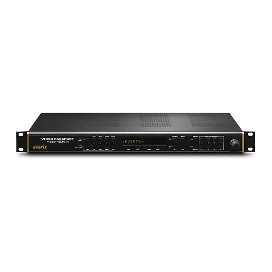
1RU Multi-Path Video Converter, Frame Synchronizer and Decoder Figure 1-1: HD2014 Video PassPort™ Front Panel Within the HD2014/12/11 architecture, 16 channels of audio are de-embedded from the input of each conversion path and sent to the internal audio processor. Eight discrete AES audio inputs and four/eight analog audio inputs can also be made available to the audio processor**.
HD2014, HD2012, HD2011 Video Passport 1RU Multi-Path Video Converter, Frame Synchronizer and Decoder Figure 1-5: HD2011 Block Diagram Revision 0.1 OVERVIEW Page 1-5...
Page 18
HD2014, HD2012, HD2011 Video Passport 1RU Multi-Path Video Converter, Frame Synchronizer and Decoder This page left intentionally blank Revision 0.1 Page 1-6 OVERVIEW...
The rear panel of the HD201x Video PassPort series is shown in Figure 2-1. The following sections will give an overview of each connection and their function including any relevant pin-out information. Figure 2-1: Rear View of HD2014 2.1.1. GPIO (General Purpose Input/Outputs) Connections The HD201x series supports eight configurable GPIOs.
HD2014, HD2012, HD2011 Video Passport 1RU Multi-Path Video Converter, Frame Synchronizer and Decoder 3.6 K internal circuit Command Figure 2-2: GPI Input Circuitry Figure 2-2 shows the internal circuit when HD201x GPIOs are configured to be General Purpose Inputs (GPIs). GPIs are active low and edge sensitive rather than level sensitive. Figure 2-3 shows the internal circuit when HD201x GPIOs are configured to be General Purpose Outputs (GPOs).
Eight (8) unbalanced AES outputs are provided on a DB15 connector. AES OUT: DB15 to BNC breakout cables are available for AES I/O (Evertz part number WPAES8- BNCM-6F). DB15 connector and breakout cable pin-out information is provided in the tables below.
Pin 15– AES Out 3 Black Wire Shell Table 2-5: AES Audio Output Breakout Cable (Evertz Part # WPAES8-BNCM-6F) 2.1.5. Analog Audio Connections ANALOG AUDIO: Analog audio is interfaced using a 36 pin analog audio terminal block. With the +AA option for the HD201x, there are eight balanced mono analog audio outputs and four balanced mono analog audio inputs on this connector.
HD2014, HD2012, HD2011 Video Passport 1RU Multi-Path Video Converter, Frame Synchronizer and Decoder Figure 2-4: Analog Audio Connector PIN # PIN OUT DESCRIPTION CH1 IN + Channel 1 Analog Audio Input + CH2 IN + Channel 2 Analog Audio Input +...
DVI source REQUIRES EDID to operate, external EDID “dongles” like the DVI DETECTIVE from Gefen can be used to ensure proper DVI operation. To connect component analog video signals to the HD201x series, Evertz breakout cable #WPDVI- DVIBNC5 (optional accessory) is required. Refer to the breakout cable diagram in Figure 2-5.
To take advantage of the HD201x’s optional multi-viewer output and its component analog video output, two additional break-out cables must be used. The first cable is Evertz breakout cable #WPDVI- DVIBNC5 (optional accessory). The second cable is Evertz breakout cable #WPDVI-DVI2 (optional accessory).
HD2014, HD2012, HD2011 Video Passport 1RU Multi-Path Video Converter, Frame Synchronizer and Decoder BLACK GREEN GREY BLUE Figure 2-6: Two Connected DVI Cables DVI OUT 1 will carry the HD201x’s DVI program output. DVI OUT 2 will carry the HD201x’s DVI internal multi-viewer output.
SDI input/outputs and the FL-CD3 enables the use of FLEX LEFT BNC1-3 as 3x additional composite analog video inputs. The Flex Right slot allows one to expand the HD2014/12/11 processing capabilities. LEFT Right: Functionality depends on the installed flex module. For example, the FR-HIO enables...
This dual purpose Green LED indicates that the HD201x has established a valid LN/ACT: linkage to its hub, and whether the HD2014 is sending or receiving data. This LED will be ON when the HD201x has established a good link to its supporting hub.
HD2014, HD2012, HD2011 Video Passport 1RU Multi-Path Video Converter, Frame Synchronizer and Decoder NOTE: Changes to the HD201x’s IP address are made via the front panel engineering menu. When using HD201x firmware revision HD2010A-20100212-1051.img or earlier changes done to the units IP address DO NOT become active until the unit is power- cycled.
HD2014, HD2012, HD2011 Video Passport 1RU Multi-Path Video Converter, Frame Synchronizer and Decoder TECHNICAL DESCRIPTION 3.1. SPECIFICATIONS 3.1.1. Coax Inputs Number of Inputs: BNC per IEC 61169-8 Annex A Connector: Input Equalization: 300m @ 270 Mbs with Belden 1694A or equivalent 100m @ 1.5 Gbs with Belden 1694A or equivalent...
HD2014, HD2012, HD2011 Video Passport 1RU Multi-Path Video Converter, Frame Synchronizer and Decoder 3.1.5. Fiber Inputs Number of Inputs: LC/UPC Connector: Dual Optical SFP Receiver (support for single mode and multi-mode fiber RX) Form Factor: 1260-1620 nm Wavelength: Auto-sensing SD and HD (270 Mbs and 1.5 Gbs) Data Rate: 525i/59.94, 720p/59.94, 1080i/59.94, 625i/50, 720p/50, 1080i/50...
HD2014, HD2012, HD2011 Video Passport 1RU Multi-Path Video Converter, Frame Synchronizer and Decoder FRONT PANEL The HD201x front panel has been designed to be a simple to use control surface. Quick access control buttons are located on the left hand side of the front panel to enable quick and easy changes to core processing parameters on a per path basis.
HD2014, HD2012, HD2011 Video Passport 1RU Multi-Path Video Converter, Frame Synchronizer and Decoder 4.1.2. Selecting the Processing Path Output Video Format Once a particular processing path has been selected for control (as per section 4.1.1) push the FMT button on the front panel. The currently selected video format will automatically appear once the FMT button is pushed.
HD2014, HD2012, HD2011 Video Passport 1RU Multi-Path Video Converter, Frame Synchronizer and Decoder 4.1.4. Selecting the Aspect Ratio Conversion Mode for the Processing Path Once a particular processing path has been selected for control (per section 4.1.1) push the ARC button on the front panel.
HD2014, HD2012, HD2011 Video Passport 1RU Multi-Path Video Converter, Frame Synchronizer and Decoder 4.1.5. Adjusting the Video Proc for the Processing Path Once a particular processing path has been selected for control (as per section 4.1.1) push the PROC button on the front panel. The list of available video proc controls for relevant processing path will then appear.
HD2014, HD2012, HD2011 Video Passport 1RU Multi-Path Video Converter, Frame Synchronizer and Decoder 4.1.8. Controlling the Analog Audio Output The AA OUT button on the front panel is designed to give quick and easy access to controls for analog audio output signals. When the AA OUT button is pressed on the front panel, the user will immediately be brought to the menu tree for the analog audio outputs.
HD2014, HD2012, HD2011 Video Passport 1RU Multi-Path Video Converter, Frame Synchronizer and Decoder 4.4. ENGINEERING MENU NAVIGATION BUTTONS The HD201x has four front panel buttons that are used for navigating the engineering menu and system control. The COARSE button is used to increase the rate at which the user may scroll COARSE: through the device parameters.
The source of video for each processing path may be selected using the PATH1, PATH2, PATH3 and PATH4 controls. In the HD2014, there will be four selections available to the user, one for each of the four processing paths in the unit. In the HD2012, there will be two selections available to the user, one for each of the two processing paths in the unit.
To access the core video processing parameters, navigate the engineering menu as follows: Video > Processing > Converter. The HD2014 has four internal video processors. The HD2012 and the HD2011 has two internal video processors. For the sake of brevity, only controls for PATH 1 will be shown in the following sections.
HD2014, HD2012, HD2011 Video Passport 1RU Multi-Path Video Converter, Frame Synchronizer and Decoder 5.1.2.2. Viewing the Sample Rate Converted Status for the Selected Path For each processing path, the status of converter’s internal sample rate converters is reported as part of the overall audio monitoring process.
HD2014, HD2012, HD2011 Video Passport 1RU Multi-Path Video Converter, Frame Synchronizer and Decoder 5.1.2.5. Enabling Closed Captions The CC Enable control allows the user to enable and disable caption insertion on the converter outputs. When the Captions control is enabled, any closed captioning will be mapped to line 21 if the output video is SD, or to the designated HD write line if the output video is HD.
HD2014, HD2012, HD2011 Video Passport 1RU Multi-Path Video Converter, Frame Synchronizer and Decoder 5.1.2.8. Setting the Type of Deinterlacer The user can adjust basic operating mode for the video de-interlacing used in the video processors with the De-Interlacer Type control. Options include Adaptive VT, Field Merge Only, Temporal Only.
HD2014, HD2012, HD2011 Video Passport 1RU Multi-Path Video Converter, Frame Synchronizer and Decoder 5.1.2.10. Setting the ifmd Mode The motion adaptive nature of the internal de-interlacer may be set to Auto, Disable or Noise Adaptive using the IFMD MODE control. Optimal processing for normal video content is achieved when set to Auto.
HD2014, HD2012, HD2011 Video Passport 1RU Multi-Path Video Converter, Frame Synchronizer and Decoder 5.1.2.13. Setting SD Blanking With the SD Blanking control, the user can adjust which standard definition lines will be blanked prior to up-converting the signal. All active video lines up to and including the selected line number will be blanked.
HD2014, HD2012, HD2011 Video Passport 1RU Multi-Path Video Converter, Frame Synchronizer and Decoder 5.1.2.15. Setting the Output Video Standard The Video Output Standard control selects the output video standard. Converters are not capable of temporal processing, so it will not convert between 59.94 and 60 or between 50 and the 60 related frame rates.
HD2014, HD2012, HD2011 Video Passport 1RU Multi-Path Video Converter, Frame Synchronizer and Decoder 5.1.2.18. Setting the Noise Reduction Level The Noise Reduction control manages the level of noise reduction to apply to the video signal. The selection levels automatically set the motion detection threshold and the aggressiveness of the filters to remove noise.
HD2014, HD2012, HD2011 Video Passport 1RU Multi-Path Video Converter, Frame Synchronizer and Decoder 5.1.2.20. Setting the Y, Cr and Cb Offset and R, G, B Offset There are three controls that set the DC Offset of each component in the Y Cb Cr space and the DC offset each component in the R G B space.
HD2014, HD2012, HD2011 Video Passport 1RU Multi-Path Video Converter, Frame Synchronizer and Decoder 5.1.2.23. Enabling the RGB Clip The RGB Clip control enables and disables the converter’s internal RGB clipper/colour legalizer. When enabled, the module will clip any illegal levels of R, G, and B (individually) to black and white levels.
HD2014, HD2012, HD2011 Video Passport 1RU Multi-Path Video Converter, Frame Synchronizer and Decoder 5.1.2.26. Setting the Saturation Gain Level With the Saturation Gain control, the user can adjust the saturation of the video signal passing through the conversion engine with a range of -50% to 100%.
HD2014, HD2012, HD2011 Video Passport 1RU Multi-Path Video Converter, Frame Synchronizer and Decoder 5.1.2.29. Setting the Aspect Ratio Converter The Aspect Ratio control sets the aspect ratio control that will be performed during the up/down/cross conversion process. Many of the standard aspect ratio conversions are listed as pre-defined options that may be selected.
HD2014, HD2012, HD2011 Video Passport 1RU Multi-Path Video Converter, Frame Synchronizer and Decoder 43to43SdPnlon169 V4:3 to 4:3 Side Panel on16:9 These settings are common up- 43to139Stchon169 V4:3 to 13:9 Stretch on 16:9 converter settings for converting 4:3 43to149Stchon169 V4:3 to 14:9 Stretch on 16:9...
HD2014, HD2012, HD2011 Video Passport 1RU Multi-Path Video Converter, Frame Synchronizer and Decoder 5.1.2.31. Setting the Input H Start The Input H Start control defines the starting horizontal portion of the input image that will be processed to the output. Input H Start does not have any effect when the pre-defined aspect ratios are used.
HD2014, HD2012, HD2011 Video Passport 1RU Multi-Path Video Converter, Frame Synchronizer and Decoder 0 to 1079 5.1.2.35. Setting the Output H Start The Output H Start control determines where to place the selected portion of the input image onto the output video raster.
HD2014, HD2012, HD2011 Video Passport 1RU Multi-Path Video Converter, Frame Synchronizer and Decoder 5.1.2.38. Setting the Output V Stop The Output V Stop control determines where to place the selected portion of the input image onto the output video raster. The Output V Stop control defines the ending vertical position for video content on the output image raster.
HD2014, HD2012, HD2011 Video Passport 1RU Multi-Path Video Converter, Frame Synchronizer and Decoder 5.1.2.41. Setting the V Filter Cutoff The V Filter Cutoff sets the vertical cutoff for the Scaler. This control manages the amount of aliasing that the vertical scaler allows to pass from its input to output when performing scaling and aspect ratio conversion.
HD2014, HD2012, HD2011 Video Passport 1RU Multi-Path Video Converter, Frame Synchronizer and Decoder 5.1.2.44. Setting the V Phase With the V Phase Offset control, you can set the vertical timing of the output video with respect to the reference. Setting this control to 0 keeps the output video frame aligned with the converter’s reference input or with the incoming video if reference is missing.
HD2014, HD2012, HD2011 Video Passport 1RU Multi-Path Video Converter, Frame Synchronizer and Decoder 5.1.2.47. Viewing the CDP Parser Each conversion path in the HD201x monitors that status of cdp captions parser on incoming video. This controls reports the status of the cdp parser.
HD2014, HD2012, HD2011 Video Passport 1RU Multi-Path Video Converter, Frame Synchronizer and Decoder 5.1.3.2. Setting the Black Clip Control The Black Clip control is used to set whether the black clip will be enabled or not. Enabling the Black Clip control forces the HD201x to clip all values below the level defined by the Black Clip Level control.
HD2014, HD2012, HD2011 Video Passport 1RU Multi-Path Video Converter, Frame Synchronizer and Decoder 5.1.3.6. Setting the Chroma Level Control This control sets the overall chroma level gain. To set the Chroma Level control, enter a value between -100 to 100 Video into the chroma level field.
HD2014, HD2012, HD2011 Video Passport 1RU Multi-Path Video Converter, Frame Synchronizer and Decoder 5.1.3.10. Setting the Line 21 Setup The Line 21 Setup control is used to set whether or not setup is removed from Line 21 of the incoming composite video signal.
HD2014, HD2012, HD2011 Video Passport 1RU Multi-Path Video Converter, Frame Synchronizer and Decoder 5.1.3.14. Setting the White Clip Control Enabling the White Clip control forces the analog video decoder to clip all values above the level defined by the White Clip Level control. Disabling the White Clip control bypasses the clipping function.
HD2014, HD2012, HD2011 Video Passport 1RU Multi-Path Video Converter, Frame Synchronizer and Decoder 5.1.3.17. Setting the Blanking Controls – Field 2 The Blanking Controls for Field 2 enable the user to set what type of video processing will be applied to lines 10 through 23 of the incoming video signal.
HD2014, HD2012, HD2011 Video Passport 1RU Multi-Path Video Converter, Frame Synchronizer and Decoder 5.1.4.3. Setting the Brightness The Brightness control allows the user to adjust the brightness of the analog video output. To set the brightness, enter a value between -32 and 32 in the Video brightness field.
HD2014, HD2012, HD2011 Video Passport 1RU Multi-Path Video Converter, Frame Synchronizer and Decoder 5.1.4.7. Setting the H Blanking The H Blanking setting enables the user to set the Horizontal blanking boundaries. To set the H blanking control, select either narrow or wide from the drop down menu.
HD2014, HD2012, HD2011 Video Passport 1RU Multi-Path Video Converter, Frame Synchronizer and Decoder 5.1.4.11. Setting the Luma Wideband Frequency Response When the Luma Bandwidth control is set to Wideband, this selects between a set of frequency response curves with a +/- 4dB range. To set the Luma Wideband Frequency Response control, enter a value between -6 to 6.
HD2014, HD2012, HD2011 Video Passport 1RU Multi-Path Video Converter, Frame Synchronizer and Decoder 5.1.4.14. Setting the VBI Processing The Vertical Blanking interval may be passed through to the composite analog video output or may be blanked. When set to Pass, VBI lines will be passed to the composite analog Video video outputs.
HD2014, HD2012, HD2011 Video Passport 1RU Multi-Path Video Converter, Frame Synchronizer and Decoder 5.1.5.2. Configuring the DVI Output Format The HD201x series has a DVI output that must be specifically configured to match the output video format that will be supplied to it.
HD2014, HD2012, HD2011 Video Passport 1RU Multi-Path Video Converter, Frame Synchronizer and Decoder 5.1.7.2. Setting the Reference Format The Reference Format control enables the user to select the reference format for the HD201x. The user can select either NTSC or PAL to be set as the reference format. The HD201x supports bi-level reference inputs only.
HD2014, HD2012, HD2011 Video Passport 1RU Multi-Path Video Converter, Frame Synchronizer and Decoder 5.1.8.2. Setting the Test Signal Generator Output The user can select on which conversion path output the test signal generator is routed to. Note that there is a single test signal generator in the HD201x. If the test signal is active on a particular path output and it is then subsequently enabled on a different path, the test signal will be automatically disabled on the first path and enabled on the second path.
8x discrete AES and 4x discrete analog (+AA option) audio inputs. In the HD2014, embedded audio from the video supplied to each of the four internal processing paths is de-embedded (16 channels) and made available for subsequent processing.
HD2014, HD2012, HD2011 Video Passport 1RU Multi-Path Video Converter, Frame Synchronizer and Decoder The controls for the audio processor are segmented into seven logical categories as shown below. The following sections will outline in detail the parameters under each of these seven categories.
HD2014, HD2012, HD2011 Video Passport 1RU Multi-Path Video Converter, Frame Synchronizer and Decoder NOTE: Deembedder 1 corresponds to the audio de-embedded from PATH1 Deembedder 2 corresponds to the audio de-embedded from PATH2, Deembedder 3 corresponds to the audio de-embedded from PATH3 Deembedder 4 corresponds to the audio de-embedded from PATH4.
Page 76
HD2014, HD2012, HD2011 Video Passport 1RU Multi-Path Video Converter, Frame Synchronizer and Decoder NOTE: Deembedder 1 corresponds to the audio de-embedded from PATH1 Deembedder 2 corresponds to the audio de-embedded from PATH2, Deembedder 3 corresponds to the audio de-embedded from PATH3 Deembedder 4 corresponds to the audio de-embedded from PATH4.
Page 77
HD2014, HD2012, HD2011 Video Passport 1RU Multi-Path Video Converter, Frame Synchronizer and Decoder The following shows the audio routing control for the X input of Embedder 1, Channel 1: This control enables the user to select an input channel from the Audio Mixer.
HD2014, HD2012, HD2011 Video Passport 1RU Multi-Path Video Converter, Frame Synchronizer and Decoder The HD201x front panel performs a real time conversion between these numerical values and its associated dB equivalent. Enter an input gain between 0 and 65535. Audio Embedder Level 0 corresponds to mute (-199 dB).
HD2014, HD2012, HD2011 Video Passport 1RU Multi-Path Video Converter, Frame Synchronizer and Decoder 5.2.4. Configuring AES Input Audio 5.2.4.1. Configuring the AES Audio per Channels Delays The HD201x accepts 8x inputs and supports per channel audio delay for each AES input channel. For the sake of brevity, the audio delay control for AES input channel 1 will be discussed in this manual.
HD2014, HD2012, HD2011 Video Passport 1RU Multi-Path Video Converter, Frame Synchronizer and Decoder 5.2.4.3. Displaying the Status of the Input The HD201x supports 8x AES inputs. The HD201x monitors the status of internal AES sample rate converters on a per channel pair basis. For the sake of brevity, the audio sample rate converter status for AES IN 1 will be discussed in this manual.
HD2014, HD2012, HD2011 Video Passport 1RU Multi-Path Video Converter, Frame Synchronizer and Decoder 5.2.5.1. Setting the AES Output Source The HD201x AES outputs can operate in several different output modes. The 8x AES outputs (16 channels) can follow output mixers for Embedder 1, Embedder 2, Embedder 3, Embedder 4 or follow the routing programmed by the AES output mixer.
Page 82
HD2014, HD2012, HD2011 Video Passport 1RU Multi-Path Video Converter, Frame Synchronizer and Decoder This control enables the user to select an input channel from the Audio Mixer. The total list of audio channel sources is dependant on aesOut the full set of audio options installed on the HD201x.
HD2014, HD2012, HD2011 Video Passport 1RU Multi-Path Video Converter, Frame Synchronizer and Decoder The following shows the inversion control for the X input of AES Out 1, Channel 1: Select enable to invert the selected channel of audio and select Audio disable to pass through the selected audio channel.
HD2014, HD2012, HD2011 Video Passport 1RU Multi-Path Video Converter, Frame Synchronizer and Decoder 5.2.6.2. Configuring the Analog Audio per Channels Delays The HD201x has 4x Analog Audio inputs with per channel audio delay control capabilities. For the sake of brevity, only the delay control for channel 1 will be described in this manual.
HD2014, HD2012, HD2011 Video Passport 1RU Multi-Path Video Converter, Frame Synchronizer and Decoder Figure 5-4: Output Audio Mixer Revision 0.1 FRONT PANEL OPERATION Page 5-51...
Page 86
HD2014, HD2012, HD2011 Video Passport 1RU Multi-Path Video Converter, Frame Synchronizer and Decoder This control enables the user to select an input channel from the Audio Mixer. The total list of audio channel sources is dependant on analogOut the full set of audio options installed on the HD201x...
HD2014, HD2012, HD2011 Video Passport 1RU Multi-Path Video Converter, Frame Synchronizer and Decoder The following shows the inversion control for the X input of analog audio out 1 Select enable to invert the selected channel of audio and select Audio disable to pass through the selected audio channel.
HD2014, HD2012, HD2011 Video Passport 1RU Multi-Path Video Converter, Frame Synchronizer and Decoder Select analog mixer to the have the analog audio outputs follow Audio the routing defined by the analog output mixer. Select one of the analogOut other options to have the analog audio outputs follow the OutputSource embedded audio outputs.
5.3.2. Setting the Default Gateway The Default Gateway control enables the user to configure the Default Gateway of the HD2014. NOTE: Changes to the HD201x’s IP address are made via the front panel engineering menu. When using HD201x firmware revision HD2010A-20100212- 1051.img or earlier changes done to the units IP address DO NOT become active...
HD2014, HD2012, HD2011 Video Passport 1RU Multi-Path Video Converter, Frame Synchronizer and Decoder 5.4. SYSTEM MENU The System menu enables the user to view version information and perform actions such as restore, delete, factory reset, etc. 5.4.1. Viewing the Product Name Accessing this menu item will display the entire name of the product.
HD2014, HD2012, HD2011 Video Passport 1RU Multi-Path Video Converter, Frame Synchronizer and Decoder 5.4.4. Factory Reset The Factory Reset menu item allows the user to reinstate the factory settings. Select the Factory Reset option if you wish to return the System configuration to its factory settings.
Need help?
Do you have a question about the HD2014 and is the answer not in the manual?
Questions and answers