Table of Contents
Advertisement
Quick Links
© Copyright 2000, 2001
EVERTZ MICROSYSTEMS LTD.
5188 John Lucas Drive, Burlington, Ontario, Canada, L7L 5Z9
Phone: 905-335-3700
Fax:
905-335-3573
Internet:
Sales:
Tech Support: service@evertz.com
Web Page:
Version 1.2 September 2003
The material contained in this manual consists of information that is the property of Evertz
Microsystems and is intended solely for the use of purchasers of the 3410 Multivert.
Microsystems expressly prohibits the use of this manual for any purpose other than the operation of the
Multivert.
All rights reserved.
permission of Evertz Microsystems Ltd. Copies of this guide can be ordered from your Evertz products
dealer or from Evertz Microsystems.
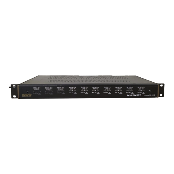
10 Channel Composite Encoder
Instruction Manual
sales@evertz.com
http://www.evertz.com
No part of this publication may be reproduced without the express written
Model 3410
Multivert
Evertz
Advertisement
Table of Contents

Related Manuals for evertz 3410 Multivert


Summary of Contents for evertz 3410 Multivert
- Page 1 Microsystems expressly prohibits the use of this manual for any purpose other than the operation of the Multivert. All rights reserved. No part of this publication may be reproduced without the express written permission of Evertz Microsystems Ltd. Copies of this guide can be ordered from your Evertz products dealer or from Evertz Microsystems.
- Page 2 WARNING Changes or Modifications not expressly approved by Evertz Microsystems Ltd. could void the user’s authority to operate the equipment. Use of unshielded plugs or cables may cause radiation interference. Properly shielded interface cables...
- Page 3 Evertz products are for informational use only and are not warranties of future performance, either express or implied. The only warranty offered by Evertz in relation to this product is the Evertz standard limited warranty, stated in the sales contract or order confirmation form.
- Page 4 Model 3410 Multivert Manual This page left intentionally blank Revision 1.2...
-
Page 5: Table Of Contents
Model 3410 Multivert Manual TABLE OF CONTENTS OVERVIEW ..........................1 INSTALLATION ........................2 2.1. REAR PANEL ............................2 2.1.1. Video Connections........................2 2.1.2. Power Connections........................3 2.2. MOUNTING ............................3 2.3. POWER REQUIREMENTS ........................4 2.3.1. Selecting the Correct Mains Voltage ..................4 2.3.2. Changing the Fuse ........................5 2.4. - Page 6 Model 3410 Multivert Manual This page left intentionally blank Revision 1.2...
-
Page 7: Overview
Model 3410 Multivert Manual OVERVIEW The Multivert, a 10 channel composite encoder, was designed for monitor wall applications where multiple SDI component video signals need to be converted to composite analog. With all ten encoders and both power supplies mounted inside the compact 1RU chassis, the Multivert proves itself to be a much better alternative to the use of expensive dongle based converters that use wall mounted or brick based power supplies. -
Page 8: Installation
Model 3410 Multivert Manual INSTALLATION 2.1. REAR PANEL Figure 2: Rear Panel The following sections describe the purpose of the rear panel connectors of the 3410. Sections 2.1.1 to 2.1.2 describe the specific generator, reader, character inserter, and telecine signals that should be connected to the 3410. -
Page 9: Power Connections
2.1.2. Power Connections LINE: The model 3410 Multivert has one or two (redundant supply is optional) universal power supplies that operate on either 115 Volt / 60 Hz or 230 Volt / 50 Hz AC. The PSU STATUS LEDs on the front panel indicate if the power supplies are operating normally. -
Page 10: Power Requirements
Model 3410 Multivert Manual Figure 5: Rear Mounting 2.3. POWER REQUIREMENTS 2.3.1. Selecting the Correct Mains Voltage Power requirements are 115 or 230 volts AC at 50 or 60 Hz. The Multivert has a universal power supply (and may have an optional redundant supply) that automatically senses the input voltage. Power should be applied by connecting a 3-wire grounding type power supply cord to each power entry module on the rear panel. -
Page 11: Changing The Fuse
2.4. CONNECTING THE VIDEO The 3410 Multivert comprises ten identical channels of composite monitoring. The input SDI video should be connected to the SDI In connector. A reclocked output of the input video is available on the SDI OUT connector and may be connected to downstream SDI devices. The SIGNAL LED located in the middle of the four BNC connectors will come on when the Multivert has detected a valid video input on the SDI In connector. -
Page 12: Front Panel Led Status Indicators
Model 3410 Multivert Manual 1. Remove the power from both power inputs. If power is being supplied to the 3410, a shock hazard exists when you remove the top cover. Make sure that you have removed power from both power cords before opening the unit. -
Page 13: Specifications
Model 3410 Multivert Manual Figure 8: Close up of Front Panel NTSC This green LED indicates that the 525 line SDI signal is present on the SDI IN connector and there is NTSC video available at the COMP output BNC connectors. -
Page 14: Electrical
Model 3410 Multivert Manual NTSC Setup: Pedestal is jumper selectable 2.6.4. Electrical Power: 115/230 V AC 50/60 Hz, 30 VA Safety: ETL listed, complies with EU safety directive EMI/RFI: Complies with FCC part 15, class A and EU EMC Directive 2.6.5.
Need help?
Do you have a question about the 3410 Multivert and is the answer not in the manual?
Questions and answers