Table of Contents
Advertisement
Quick Links
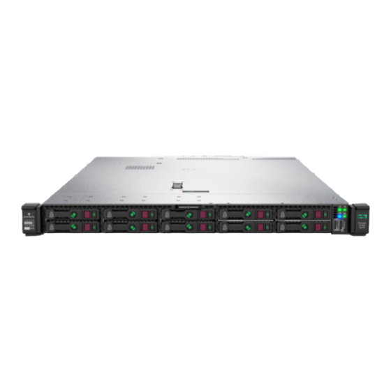
HPE ProLiant DX360 Gen10 Server User Guide
Abstract
This document is for the person who installs, administers, and troubleshoots servers and storage systems.
Hewlett Packard Enterprise assumes you are qualified in the servicing of computer equipment and trained in
recognizing hazards in products with hazardous energy levels.
Part Number: P19004-002
Published: September 2019
Edition: 2
Advertisement
Table of Contents

Related Manuals for HPE ProLiant DX360 Gen10


Summary of Contents for HPE ProLiant DX360 Gen10
- Page 1 HPE ProLiant DX360 Gen10 Server User Guide Abstract This document is for the person who installs, administers, and troubleshoots servers and storage systems. Hewlett Packard Enterprise assumes you are qualified in the servicing of computer equipment and trained in recognizing hazards in products with hazardous energy levels.
- Page 2 © Copyright 2019 Hewlett Packard Enterprise Development LP Notices The information contained herein is subject to change without notice. The only warranties for Hewlett Packard Enterprise products and services are set forth in the express warranty statements accompanying such products and services. Nothing herein should be construed as constituting an additional warranty.
-
Page 3: Table Of Contents
Hot-plug drive LED definitions.....................................25 NVMe SSD LED definitions..................................... 26 uFF drive components and LEDs..................................27 Hot-plug fans..........................................28 HPE Smart Array P824i-p MR Gen10 Controller............................30 Operations........................31 Power up the server........................................31 Power down the server......................................31 Extend the server from the rack..................................31 Remove the server from the rack..................................32... - Page 4 Installing an HPE Smart Array P408i-p SR Gen10 Controller option............... 104 Installing an HPE Smart Array P816i-a SR Gen10 Controller option................107 Installing an HPE Smart Array P824i-p MR Gen10 controller in a configured server........110 Installing the operating system with the HPE Smart Array MR Gen10 P824i-p controller driver..111...
- Page 5 Energy pack option configurations..............................131 HPE Trusted Platform Module 2.0 Gen10 option..........................136 Overview........................................136 HPE Trusted Platform Module 2.0 Guidelines........................137 Installing and enabling the HPE TPM 2.0 Gen10 Kit......................137 Cabling..........................142 Cabling overview ........................................142 SFF cables............................................142 SFF backplane to P824i-p controller............................143 8 SFF backplane to a P408i-a/P816i-a controller........................144...
- Page 6 HPE 500W Flex Slot Platinum Hot-plug Low Halogen Power Supply..............168 HPE 800W Flex Slot Platinum Hot-plug Low Halogen Power Supply..............169 HPE 800W Flex Slot Titanium Hot-plug Low Halogen Power Supply..............170 HPE 800W Flex Slot Universal Hot-plug Low Halogen Power Supply..............171 HPE 800W Flex Slot -48VDC Hot-plug Low Halogen Power Supply...............
-
Page 7: Component Identification
Component identification Front panel components 8 SFF Item Description Serial label pull tab Display port (optional) Optical drive (optional) USB 2.0 port (optional) USB 3.0 port iLO Service Port The operating system does not recognize this port as a USB port. SAS/SATA drive bays 4 LFF Item... -
Page 8: Front Panel Leds And Buttons
Item Description iLO Service Port The operating system does not recognize this port as a USB port. USB 3.0 port SAS/SATA drive bays 10 SFF NVMe/SAS Combo Item Description Serial label pull tab Systems Insight Display (optional) USB 3.0 port SAS/SATA/NVMe drive bays When the 10 SFF NVMe/SAS backplane option is installed, NVMe drives must be installed in bays 9 and 10. - Page 9 Item Description Status UID button/LED Solid blue = Activated Flashing blue: • 1 Hz = Remote management or firmware upgrade in progress • 4 Hz = iLO manual reboot sequence initiated • 8 Hz = iLO manual reboot sequence in progress Off = Deactivated Power On/Standby button and Solid green = System on...
- Page 10 4 LFF Item Description Status UID button/LED Solid blue = Activated. Flashing blue: • 1 Hz = Remote management or firmware upgrade in progress. • 4 Hz = iLO manual reboot sequence initiated. • 8 Hz = iLO manual reboot sequence in progress. Off = Deactivated.
-
Page 11: Uid Button Functionality
The UID button can be used to display the Server Health Summary when the server will not power on. For more information, see the latest HPE iLO 5 User Guide on the Hewlett Packard Enterprise website. Front panel LED power fault codes The following table provides a list of power fault codes, and the subsystems that are affected. - Page 12 Description Status Processor LEDs Off = Normal Amber = Failed processor DIMM LEDs Off = Normal Amber = Failed DIMM or configuration issue Fan LEDs Off = Normal Amber = Failed fan or missing fan NIC LEDs Off = No link to network Solid green = Network link Flashing green = Network link with activity If power is off, the front panel LED is not active.
-
Page 13: Systems Insight Display Combined Led Descriptions
Systems Insight Display combined LED descriptions The combined illumination of the following LEDs indicates a system condition: • Systems Insight Display LEDs • System power LED • Health LED Systems Insight Display LED Health LED System power Status and color Processor (amber) Amber One or more of the following conditions... -
Page 14: Rear Panel Components
Systems Insight Display LED Health LED System power Status and color Power supply (amber) Amber Green One or more of the following conditions may exist: • Redundant power supply is installed and only one power supply is functional. • AC power cord is not plugged into redundant power supply. -
Page 15: Rear Panel Leds
Item Description Serial port (optional) USB 3.0 ports FlexibleLOM (optional) Rear panel LEDs Item Description Status UID LED Solid blue = Identification is activated. Flashing blue = System is being managed remotely. Off = Identification is deactivated. iLO 5/standard NIC Solid green = Activity exists. -
Page 16: System Board Components
Item Description Status Power supply 2 LED Solid green = Normal Off = One or more of the following conditions exists: • AC power unavailable • Power supply failed • Power supply in standby mode • Power supply exceeded current limit. Power supply 1 LED Solid green = Normal Off = One or more of the following conditions... -
Page 17: System Maintenance Switch Descriptions
Item Description Front display port/USB 2.0 connector x4 SATA port 1 x4 SATA port 2 x2 SATA port 3 x1 SATA port 4 Front power/USB 3.0 connector Optical/SATA port 5 Energy pack connector Micro SD card slot Chassis Intrusion Detection connector Drive backplane power connector Dual internal USB 3.0 connector Type-a SmartArray connector... -
Page 18: Nmi Functionality
Position Default Function — Reserved — Reserved — Reserved To access the redundant ROM, set S1, S5, and S6 to On. When the system maintenance switch position 6 is set to the On position, the system is prepared to restore all configuration settings to their manufacturing defaults. - Page 19 Item Description Example Capacity 8 GB 16 GB 32 GB 64 GB 128 GB Rank 1R = Single rank 2R = Dual rank 4R = Quad rank 8R = Octal rank Data width on DRAM x4 = 4-bit x8 = 8-bit x16 = 16-bit Memory generation PC4 = DDR4...
-
Page 20: Nvdimm Identification
R = RDIMM (registered) L = LRDIMM (load reduced) E = Unbuffered ECC (UDIMM) For more information about product features, specifications, options, configurations, and compatibility, see the HPE DDR4 SmartMemory QuickSpecs on the Hewlett Packard Enterprise website (http://www.hpe.com/support/ DDR4SmartMemoryQS). NVDIMM identification NVDIMM boards are blue instead of green. -
Page 21: Nvdimm Led Identification
— For more information about NVDIMMs, see the product QuickSpecs on the Hewlett Packard Enterprise website (http:// www.hpe.com/info/qs). NVDIMM 2D Data Matrix barcode The 2D Data Matrix barcode is on the right side of the NVDIMM label and can be scanned by a cell phone or other device. - Page 22 NVDIMM-N LED combinations State Definition NVDIMM-N Power LED NVDIMM-N Function LED (green) (blue) AC power is on (12V rail) but the NVM controller is not working or not ready. AC power is on (12V rail) and the NVM controller is ready. AC power is off or the battery is off (12V rail off).
-
Page 23: Hpe Persistent Memory Module Label Identification
QR code Includes part number and serial number For more information about product features, specifications, options, configurations, and compatibility, see the product QuickSpecs on the Hewlett Packard Enterprise website (http://www.hpe.com/support/persistentmemoryQS). Device numbers 8 SFF device bay numbering 8 SFF + 2 SFF device bay numbering... - Page 24 NVMe and SAS drives. Optional rear device bay numbering The optional rear device bay supports either 1 SFF drive in a SmartDrive carrier, or 2 uFF M.2 drives in an HPE Smart Carrier M.2 (SCM).
-
Page 25: Hot-Plug Drive Led Definitions
Hot-plug drive LED definitions Item Status Definition Locate Solid blue The drive is being identified by a host application. Flashing blue The drive carrier firmware is being updated or requires an update. Activity ring Rotating green Drive activity. No drive activity. Do not remove Solid white Do not remove the drive. -
Page 26: Nvme Ssd Led Definitions
NVMe SSD LED definitions The NVMe SSD is a PCIe bus device. A device attached to a PCIe bus cannot be removed without allowing the device and bus to complete and cease the signal/traffic flow. CAUTION: Do not remove an NVMe SSD from the drive bay while the Do not remove LED is flashing. The Do not remove LED flashes to indicate that the device is still in use. -
Page 27: Uff Drive Components And Leds
Item Status Definition Flashing white The drive ejection request is pending. The drive has been ejected. Power Solid green Do not remove the drive. The drive must be ejected from the PCIe bus prior to removal. Flashing green The drive ejection request is pending. The drive has been ejected. -
Page 28: Hot-Plug Fans
Item Description Status Drive status LED • Off—The drive is not configured by a RAID controller • Solid green—The drive is a member of one or more logical drives • Flashing green (4 Hz)—The drive is operating normally and has activity •... - Page 29 They are also required for ASHRAE-compliant configurations. For more information on ASHRAE- compliant configurations, see the Hewlett Packard Enterprise website http://www.hpe.com/servers/ASHRAE. The server supports variable fan speeds. The fans operate at minimum speed until a temperature change requires a fan speed increase to cool the server.
-
Page 30: Hpe Smart Array P824I-P Mr Gen10 Controller
HPE Smart Array P824i-p MR Gen10 Controller Components Item Description Internal SAS port 1i Internal SAS port 2i Internal SAS port 3i Internal SAS port 4i Controller backup power cable connector Internal SAS port 5i Internal SAS port 6i Component identification... -
Page 31: Operations
Operations Power up the server To power up the server, use one of the following methods: • Press the Power On/Standby button. • Use the virtual power button through iLO. Power down the server Before powering down the server for any upgrade or maintenance procedures, perform a backup of critical server data and programs. -
Page 32: Remove The Server From The Rack
WARNING: To reduce the risk of personal injury, be careful when pressing the server rail-release latches and sliding the server into the rack. The sliding rails could pinch your fingers. 5. After performing the installation or maintenance procedure, slide the server into the rack: a. -
Page 33: Remove The Hot-Plug Fan
The access panel slides to a closed position. 3. Tighten the security screw on the latch, if needed. Remove the hot-plug fan Procedure 1. Observe the following alert: IMPORTANT: After removing a high-performance (dual-rotor) fan, install or replace the fan within 60 seconds. Otherwise, the server will shut down gracefully. -
Page 34: Remove The Primary Pci Riser Cage
CAUTION: Do not operate the server for long periods with the access panel open or removed. Operating the server in this manner results in improper airflow and improper cooling that can lead to thermal damage. IMPORTANT: For optimum cooling, install fans in all primary fan locations. To replace the component, reverse the removal procedure. -
Page 35: Install The Primary Pci Riser Cage
Install the primary PCI riser cage Procedure 1. Install the PCI riser cage. 2. Install the access panel (Install the access panel on page 32). 3. Install the server into the rack (Installing the server into the rack on page 45). 4. -
Page 36: Remove The Secondary Pci Riser Cage
Remove the secondary PCI riser cage Procedure Observe the following alert: CAUTION: To prevent damage to the server or expansion boards, power down the server and remove all AC power cords before removing or installing the PCI riser cage. Back up all server data. Power down the server (Power down the server on page 31). -
Page 37: Install The Secondary Pci Riser Cage
Install the secondary PCI riser cage Procedure 1. Install the PCI riser cage. 2. If needed, install expansion boards (Installing an expansion board in the secondary riser cage on page 95). 3. Install the access panel (Install the access panel on page 32). 4. -
Page 38: Remove The 8 Sff Drive Backplane
Remove the 8 SFF drive backplane Procedure 1. Back up all server data. 2. Power down the server (Power down the server on page 31). 3. Remove all power: a. Disconnect each power cord from the power source. b. Disconnect each power cord from the server. 4. - Page 39 Operations...
-
Page 40: Setup
Delivered by experienced, certified engineers, Hewlett Packard Enterprise support services help you keep your servers up and running with support packages tailored specifically for HPE ProLiant systems. Hewlett Packard Enterprise support services let you integrate both hardware and software support into a single package. A number of service level options are available to meet your business and IT needs. -
Page 41: Temperature Requirements
When vertical space in the rack is not filled by a server or rack component, the gaps between the components cause changes in airflow through the rack and across the servers. Cover all gaps with blanking panels to maintain proper airflow. CAUTION: Always use blanking panels to fill empty vertical spaces in the rack. -
Page 42: Electrical Grounding Requirements
Electrical grounding requirements The server must be grounded properly for proper operation and safety. In the United States, you must install the equipment in accordance with NFPA 70, 1999 Edition (National Electric Code), Article 250, as well as any local and regional building codes. -
Page 43: Server Warnings And Cautions
1. Cut the DC power cord ends no shorter than 150 cm (59.06 in). 2. If the power source requires ring tongues, use a crimping tool to install the ring tongues on the power cord wires. IMPORTANT: The ring terminals must be UL approved and accommodate 12 gauge wires. IMPORTANT: The minimum nominal thread diameter of a pillar or stud type terminal must be 3.5 mm (0.138 in);... -
Page 44: Rack Warnings
CAUTION: Protect the server from power fluctuations and temporary interruptions with a regulating uninterruptible power supply. This device protects the hardware from damage caused by power surges and voltage spikes and keeps the system in operation during a power failure. CAUTION: Do not operate the server for long periods with the access panel open or removed. -
Page 45: Installing Hardware Options
Failure to observe UEFI requirements for ProLiant Gen10 servers can result in errors installing the operating system, failure to recognize boot media, and other boot failures. For more information on these requirements, see the HPE UEFI Requirements on the Hewlett Packard Enterprise website. -
Page 46: Installing The Operating System With Intelligent Provisioning
• Intelligent Provisioning—For single-server deployment, updating, and provisioning capabilities. For more information, see Installing the operating system with Intelligent Provisioning on page 46. • Insight Control server provisioning—For multiserver remote OS deployment, use Insight Control server provisioning for an automated solution. For more information, see the Insight Control documentation on the Hewlett Packard Enterprise website. -
Page 47: Registering The Server
Procedure 1. Press the Power On/Standby button. 2. Do one of the following: To enter the UEFI System Utilities screen and modify the server configuration ROM default settings, press the F9 • key on the ProLiant POST screen. Choose one of the following boot modes: ◦... -
Page 48: Hardware Options Installation
Hewlett Packard Enterprise product QuickSpecs For more information about product features, specifications, options, configurations, and compatibility, see the product QuickSpecs on the Hewlett Packard Enterprise website (http://www.hpe.com/info/qs). Introduction Install any hardware options before initializing the server. For options installation information, see the option documentation. -
Page 49: Memory Options
DIMM and NVDIMM population information For specific DIMM and NVDIMM population information, see the DIMM population guidelines on the Hewlett Packard Enterprise website (http://www.hpe.com/docs/memory-population-rules). DIMM-processor compatibility The installed processor determines the type of DIMM that is supported in the server:... -
Page 50: Hpe Smartmemory Speed Information
Second-generation Intel Xeon Scalable processors support DDR4-2933 DIMMs. Mixing DIMM types is not supported. Install only the supported DDR4-2666 or DDR4-2933 DIMMs in the server. HPE SmartMemory speed information For more information about memory speed information, see the Hewlett Packard Enterprise website (https:// www.hpe.com/docs/memory-speed-table). -
Page 51: Hpe 16Gb Nvdimm Option
The server can support up to 12 NVDIMMs in 2 socket servers (up to 192GB) and up to 24 NVDIMMs in 4 socket servers (up to 384GB). The HPE Smart Storage Battery provides backup power to the memory slots allowing data to be moved from the DRAM portion of the NVDIMM to the Flash portion for persistence during a power down event. - Page 52 CAUTION: Unlike traditional storage devices, NVDIMMs are fully integrated in with the ProLiant server. Data loss can occur when system components, such as the processor or HPE Smart Storage Battery, fails. HPE Smart Storage battery is a critical component required to perform the backup functionality of NVDIMMs. It is important to act when HPE Smart Storage Battery related failures occur.
- Page 53 • Installing an energy pack in the 10 SFF SAS/SATA/NVMe Combo backplane configuration on page 132 Install any components removed to access the DIMM slots and the HPE Smart Storage Battery. 10. Install the access panel. 11. Slide or install the server into the rack.
- Page 54 (such as disintegrate, pulverize, melt, incinerate, or shred) The NVDIMM-N Sanitize options are intended to meet the Purge level. For more information on sanitization for NVDIMMs, see the following sections in the HPE 16GB NVDIMM User Guide on the Hewlett Packard Enterprise website (http://www.hpe.com/info/nvdimm-docs): •...
-
Page 55: Hpe Persistent Memory Option
HPE Persistent Memory option HPE Persistent Memory, which offers the flexibility to deploy as dense memory or fast storage and features Intel Optane DC Persistent Memory, enables per-socket memory capacity of up to 3.0 TB. HPE Persistent Memory, together with traditional volatile DRAM DIMMs, provide fast, high-capacity, cost-effective memory and storage to transform big data workloads and analytics by enabling data to be stored, moved, and processed quickly. - Page 56 Installing HPE Persistent Memory modules Use this procedure only for new HPE Persistent Memory module installations. If you are migrating this HPE Persistent Memory module from another server, see the HPE Persistent Memory User Guide on the Hewlett Packard Enterprise website (http://www.hpe.com/info/persistentmemory-docs).
- Page 57 DIMM or HPE Persistent Memory module with the corresponding notches in the slot before installing the component. Do not force the DIMM or HPE Persistent Memory module into the slot. When installed properly, not all DIMMs or HPE Persistent Memory modules will face in the same direction.
-
Page 58: Installing A High-Performance Fan
• HPE Persistent Memory Management Utility—The HPE Persistent Memory Management Utility is a desktop application used to configure the server for HPE Persistent Memory, as well as evaluate and monitor the server memory configuration layout. For more information, see the HPE Persistent Memory User Guide on the Hewlett Packard Enterprise website (http:// www.hpe.com/info/persistentmemory-docs). - Page 59 Prerequisites Before installing this option, be sure you have the following: The components included with the hardware option kit Procedure Observe the following alert: IMPORTANT: After removing a high-performance (dual-rotor) fan, install or replace the fan within 60 seconds. Otherwise, the server will shut down gracefully. Power down the server (Power down the server on page 31).
-
Page 60: Drive Options
Install high-performance fans in each of the seven fan bays. If needed, ensure each fan is securely installed by pressing the tab. Do not press on other areas of the fan. Install the access panel (Install the access panel on page 32). 10. -
Page 61: Hot-Plug Drive Guidelines
• The system automatically sets all device numbers. • If only one hard drive is used, install it in the bay with the lowest device number. • Drives should be the same capacity to provide the greatest storage space efficiency when drives are grouped together into the same drive array. -
Page 62: Removing A Hot-Plug Sas Or Sata Hard Drive
3. Install the drive. 4. Determine the status of the drive from the drive LED definitions (Hot-plug drive LED definitions on page 25). Removing a hot-plug SAS or SATA hard drive CAUTION: For proper cooling, do not operate the server without the access panel, baffles, expansion slot covers, or blanks installed. - Page 63 Prerequisites NVMe drives are supported in the 8SFF and 10 SFF server configurations. Before installing this option, be sure you have the following: The components included with the hardware option kit Procedure 1. Observe the following alert: CAUTION: To prevent improper cooling and thermal damage, do not operate the server unless all bays are populated with either a component or a blank.
-
Page 64: Removing And Replacing An Nvme Drive
Removing and replacing an NVMe drive An NVMe SSD is a PCIe BUS device. Devices attached to a PCIe bus cannot be removed without allowing the device and the bus to complete and cease signal/traffic flow. Procedure 1. Back up all server data. 2. -
Page 65: Removing And Replacing A Uff Drive
3. Install the drives. Push firmly near the ejection handle until the latching spring engages with the drive bay. 4. Power on the server. To configure the drive, use HPE Smart Storage Administrator. Removing and replacing a uFF drive Procedure 1. -
Page 66: Installing An 8 Sff Optical Drive
To remove the drive carrier: To replace the component, reverse the removal procedure. Installing an 8 SFF optical drive Prerequisites Before installing an optical drive, be sure the 8 SFF display port/USB/optical blank option is installed. For more information, see Installing an 8 SFF display port/USB/optical blank option on page 75. Procedure 1. - Page 67 2. Install the optical drive. 3. Connect the optical drive cable. Hardware options installation...
-
Page 68: Universal Media Bay Options
Universal media bay options are compatible only with the 8SFF chassis. Hewlett Packard Enterprise recommends installing the P816i-a controller to support 10 SAS/SATA drives. For more information, see Installing an HPE Smart Array P816i-a SR Gen10 Controller option on page 107. In addition, be sure that you have the following: •... - Page 69 a. Extend the server from the rack on page 31. b. Remove the server from the rack on page 32. Remove the access panel on page 32. Remove the universal media bay blank. Install the 2 SFF SAS/SATA drive cage. Route and connect the data cable.
-
Page 70: Installing A 2 Sff Nvme Drive Cage Option
Route and connect the power cable. 10. Install the access panel (Install the access panel on page 32). 11. Install the server in the rack. 12. Connect each power cord to the server. 13. Connect each power cord to the power source. 14. - Page 71 • The components included with the hardware option kit • T-10 Torx screwdriver • T-15 Torx screwdriver Additional cables, as needed. For more information, see SFF cables on page 142. • • NVMe drives For more information, contact a Hewlett Packard Enterprise authorized reseller. Procedure Back up all server data.
- Page 72 Remove the primary PCI riser cage (Remove the primary PCI riser cage on page 34). Use a T-15 Torx screwdriver to remove the existing riser board. 10. Use a T-15 Torx screwdriver to install the riser provided in the kit in the primary PCI riser cage. 11.
-
Page 73: Installing A 2 Sff Hpe Smart Carrier M.2 (Scm) Drive Cage
Hewlett Packard Enterprise recommends installing the P816i-a controller to support more than eight SAS/SATA drives. For more information, see Installing an HPE Smart Array P816i-a SR Gen10 Controller option on page 107. Before installing this option, be sure you that have the following: •... - Page 74 a. Disconnect each power cord from the power source. b. Disconnect each power cord from the server. Do one of the following: a. Extend the server from the rack on page 31. b. Remove the server from the rack on page 32. Remove the access panel on page 32.
-
Page 75: Installing An 8 Sff Display Port/Usb/Optical Blank Option
Route and connect the power cable. 10. Install the access panel (Install the access panel on page 32). 11. Install the server in the rack. 12. Connect each power cord to the server. 13. Connect each power cord to the power source. 14. - Page 76 • The components included with the hardware option kit • T-10 Torx screwdriver • An optical drive, if installing For more information, contact a Hewlett Packard Enterprise authorized reseller. Procedure Back up all server data. Power down the server (Power down the server on page 31). Remove all power: a.
-
Page 77: Installing The 4 Lff Optical Drive Option
Route and connect the data cable. If needed, install an optical drive (Installing an 8 SFF optical drive on page 66). 10. Install the access panel (Install the access panel on page 32). 11. Install the server in the rack. 12. - Page 78 • The components included with the hardware option kit. • T-10 Torx screwdriver. • LFF optical cable option kit. • An optical drive. For more information, contact a Hewlett Packard Enterprise authorized reseller. Procedure Back up all server data. Power down the server on page 31. Remove all power: a.
-
Page 79: Installing The Rear Drive Riser Cage Option
Connect the optical drive cable to the optical drive backplane and to the SATA optical/storage drive connector. Install the access panel (Install the access panel on page 32). 10. Install the server in the rack. 11. Connect each power cord to the server. 12. - Page 80 • The components included with the hardware option kit. • T-10 and T-15 Torx screwdriver. • 1 SFF drive, 2 uFF M.2 drives, or blanks. Procedure Power down the server on page 31. Remove all power: a. Disconnect each power cord from the power source. b.
- Page 81 If needed, install the riser board removed in step 7 on the rear drive riser cage bracket. 10. Install the drive cage on the riser cage. 11. If needed, install the riser cage bracket on the rear drive riser cage. Hardware options installation...
- Page 82 12. If needed, install an expansion board (Installing an expansion board in the primary riser cage on page 87). 13. Install the rear drive riser cage in the primary riser cage position. 14. Route and connect the data and power cables. Hewlett Packard Enterprise recommends using embedded SATA solutions when connecting the cable.
-
Page 83: Primary Pci Riser Cage Options
15. Install drives or blanks (Drive options on page 60). 16. Install the access panel (Install the access panel on page 32). 17. Install the server in the rack. 18. Power up the server on page 31. 19. Connect each power cord to the server. 20. - Page 84 Remove all power: a. Disconnect each power cord from the power source. b. Disconnect each power cord from the server. Do one of the following: a. Extend the server from the rack (Extend the server from the rack on page 31). b.
-
Page 85: Installing The Sata M.2 2280 Riser Option
Expansion boards (Installing an expansion board in the primary riser cage on page 87) • GPU (Installing an accelerator or GPU in the primary riser cage) • • Controllers (Controller options on page 100) 11. Install the riser cage (Install the primary PCI riser cage on page 35). 12. - Page 86 Remove the existing riser board from the riser cage. Install the M.2 riser board. Remove the screw securing the standoff on the riser. 10. Install the M.2 drives. Hardware options installation...
-
Page 87: Installing An Expansion Board In The Primary Riser Cage
11. Install the following, as needed: Expansion boards (Installing an expansion board in the primary riser cage on page 87) • Controllers (Controller options on page 100) • 12. Install the primary PCI riser cage (Install the primary PCI riser cage on page 35). 13. -
Page 88: Installing An Accelerator Or Gpu In The Primary Riser Cage
Use a T-10 Torx screwdriver to Install the expansion board. 10. Connect any required internal or external cables to the expansion board. 11. Install the primary PCI riser cage (Install the primary PCI riser cage on page 35). 12. Install the access panel (Install the access panel on page 32). 13. - Page 89 • The components included with the hardware option kit. • HPE Gen10 CPU1 Cable Kit (if installing a high-powered GPU kit) for your server. Procedure Observe the following alerts: WARNING: To reduce the risk of personal injury from hot surfaces, allow the drives and the internal system components to cool before touching them.
-
Page 90: Secondary Pci Riser Options
10. If the card requires rear support, install the GPU support bracket. 11. Install the primary PCI riser cage on page 35. 12. Install the access panel (Install the access panel on page 32). 13. Install the server in the rack. 14. - Page 91 Before installing this option, be sure you have the following: • The components included with the hardware option kit • Any expansion boards or controllers you plan to install • T-10 Torx screwdriver • T-15 Torx screwdriver Procedure Power down the server (Power down the server on page 31). Remove all power: a.
- Page 92 Lift and remove the secondary riser cage latch. Use a T-15 Torx screwdriver to remove the riser cage screw. Install the full height PCIe x16 riser cage latch. Use a T-15 Torx screwdriver to remove the riser cage screw. Hardware options installation...
- Page 93 10. Install the riser cage. 11. Install one of the following, as needed: • Expansion boards (Installing an expansion board in the secondary riser cage on page 95) GPU (Installing an accelerator or GPU in the secondary riser cage on page 98) •...
-
Page 94: Installing A Secondary Low-Profile Pcie Slot Riser Cage Option
Installing a secondary low-profile PCIe slot riser cage option When installed, this riser cage provides an additional low profile slot and supports half-length/half-height expansion boards. Prerequisites This option requires a dual processor configuration. Before installing this option, be sure that you have the following: The components included with the hardware option kit Procedure Observe the following alerts:... -
Page 95: Installing An Expansion Board In The Secondary Riser Cage
Install one of the following, as needed: Expansion boards (Installing an expansion board in the secondary riser cage on page 95) • • Controllers (Controller options on page 100) Install the access panel (Install the access panel on page 32). 10. - Page 96 Power down the server (Power down the server on page 31). Remove all power: a. Disconnect each power cord from the power source. b. Disconnect each power cord from the server. Do one of the following: a. Extend the server from the rack (Extend the server from the rack on page 31). b.
- Page 97 • Full-length Install the expansion board. Hardware options installation...
-
Page 98: Installing An Accelerator Or Gpu In The Secondary Riser Cage
10. Connect any required internal or external cables to the expansion board. 11. Install the access panel (Install the access panel on page 32). 12. Install the server in the rack. 13. Connect each power cord to the server. 14. Connect each power cord to the power source. 15. - Page 99 CAUTION: To prevent damage to electrical components, properly ground the server before beginning any installation procedure. Improper grounding can cause electrostatic discharge. Back up all server data. Power down the server (Power down the server on page 31). Remove all power: a.
-
Page 100: Controller Options
11. Install the card in the riser cage, and then connect any required cables, if applicable. 12. If installing a GPU requiring greater than 75 W, connect the power cable to the primary riser power connector. 13. Install the access panel (Install the access panel on page 32). 14. -
Page 101: Installing An Hpe Smart Array P408I-A Sr Gen10 Controller Option
• The controller data sheet on the Hewlett Packard Enterprise website (https://www.hpe.com/h20195/V2/ Getdocument.aspx?docname=a00017196enw) • The controller QuickSpecs on the Hewlett Packard Enterprise website (http://www.hpe.com/info/qs). Installing an HPE Smart Array P408i-a SR Gen10 Controller option Prerequisites Before installing this option, be sure that you have the following: •... - Page 102 Connect the cables. • 8 SFF • 10 SFF SAS/SATA NVMe Combo Hardware options installation...
- Page 103 • 4 LFF IMPORTANT: To enable SmartCache or CacheCade in a P-class type-p Smart Array controller, you must: • Connect the controller backup power cable to the controller backup power connector on the system or riser board. • Connect the energy pack cable to the energy pack connector on the system board. Hardware options installation...
-
Page 104: Installing An Hpe Smart Array P408I-P Sr Gen10 Controller Option
11. Connect each power cord to the server. 12. Connect each power cord to the power source. 13. Power up the server on page 31. Installing an HPE Smart Array P408i-p SR Gen10 Controller option Prerequisites Before installing this option, be sure you that have the following: •... - Page 105 a. Disconnect each power cord from the power source. b. Disconnect each power cord from the server. Do one of the following: a. Extend the server from the rack on page 31. b. Remove the server from the rack on page 32. Remove the access panel on page 32.
- Page 106 10. Install the primary PCI riser cage (Install the primary PCI riser cage on page 35). 11. Connect the cables. • 8 SFF • 4 LFF IMPORTANT: To enable SmartCache or CacheCade in a P-class type-p Smart Array controller, you must: •...
-
Page 107: Installing An Hpe Smart Array P816I-A Sr Gen10 Controller Option
14. Connect each power cord to the server. 15. Connect each power cord to the power source. 16. Power up the server on page 31. Installing an HPE Smart Array P816i-a SR Gen10 Controller option Prerequisites Before installing this option, be sure that you have the following: •... - Page 108 Remove all power: a. Disconnect each power cord from the power source. b. Disconnect each power cord from the server. Do one of the following: a. Extend the server from the rack on page 31. b. Remove the server from the rack on page 32. Remove the access panel on page 32.
- Page 109 IMPORTANT: To enable SmartCache or CacheCade in a P-class type-p Smart Array controller, you must: • Connect the controller backup power cable to the controller backup power connector on the system or riser board. • Connect the energy pack cable to the energy pack connector on the system board. Install the access panel (Install the access panel on page 32).
-
Page 110: Installing An Hpe Smart Array P824I-P Mr Gen10 Controller In A Configured Server
Installing an HPE Smart Array P824i-p MR Gen10 controller in a configured server Procedure Back up data on the system. Close all applications. Update the server firmware if it is not the latest revision. Do one of the following: •... -
Page 111: Installing The Operating System With The Hpe Smart Array Mr Gen10 P824I-P Controller Driver
Installing the operating system with the HPE Smart Array MR Gen10 P824i-p controller driver Prerequisites Ensure that you have the HPE Smart Array MR Gen10 P824i-p controller driver available. Obtain it by extracting it from the SPP (http://www.hpe.com/servers/spp) or by downloading it from the Hewlett Packard Enterprise Support website https://www.support.hpe.com. -
Page 112: Processor And Heatsink Options
Installing a processor heatsink assembly The server supports single-processor and dual processor operations. IMPORTANT: Existing HPE ProLiant and HPE Synergy Gen10 server products containing first-generation Intel Xeon Scalable processors may not be upgraded to second-generation Intel Xeon Scalable processors at this time. - Page 113 CAUTION: If installing a processor with a faster speed, update the system ROM before installing the processor. To download firmware and view installation instructions, see the Hewlett Packard Enterprise Support Center website. CAUTION: THE CONTACTS ARE VERY FRAGILE AND EASILY DAMAGED. To avoid damage to the socket or processor, do not touch the contacts.
-
Page 114: Installing A High-Performance Heatsink
To determine when a high-performance heatsink should be installed in the server, see the server QuickSpecs on the Hewlett Packard Enterprise website (http://www.hpe.com/info/qs). Before installing this option, be sure that you have the following: •... - Page 115 Hewlett Packard Enterprise recommends using a nonconductive tool. Procedure Observe the following alerts. CAUTION: The processor assembly must be removed and replaced as a unit. Do not remove the processor from the carrier. CAUTION: When handling the heatsink, always hold it along the top and bottom of the fins. Holding it from the sides can damage the fins.
- Page 116 c. Lift the processor heatsink assembly up and away from the system board. d. Turn the processor heatsink assembly over and place it on a work surface with the processor assembly facing up. Release the thermal grease adhesion between the processor assembly and heatsink: a.
- Page 117 The processor remains attached to the carrier. Using an alcohol wipe, remove the existing thermal grease from the processor and heatsink. Allow the alcohol to evaporate before continuing. 10. Remove the plastic cover over the thermal grease on the high-performance heatsink. 11.
-
Page 118: Processor, Heatsink, And Socket Components
Processor, heatsink, and socket components Item Description Heatsink nuts Processor carrier Pin 1 indicator Heatsink latch Alignment post Symbol also on the processor and frame. Hardware options installation... -
Page 119: Installing The Systems Insight Display Power Module
Installing the Systems Insight Display power module Prerequisites Before installing this option, be sure you have the following: • The components included with the hardware option kit • T-10 Torx screwdriver Procedure Observe the following alerts: WARNING: To reduce the risk of personal injury from hot surfaces, allow the drives and the internal system components to cool before touching them. - Page 120 Using a Torx T-10 screwdriver, remove the Power/UID/USB assembly. • 8 SFF • 4 LFF Hardware options installation...
- Page 121 Guide the SID cable through the front of the server. 10. Install the SID module into the front panel. Using a T-10 Torx screwdriver, secure the module to the chassis with the screws from the kit. • 8 SFF Hardware options installation...
- Page 122 • 4 LFF 11. Connect the SID cables to the front power button/USB 3.0 connector on the system board. Hardware options installation...
-
Page 123: Installing The 4 Lff Display Port/Usb Module
Installing the 4 LFF display port/USB module Prerequisites Before installing this option, be sure you have the following: • The components included with the hardware option kit • T-10 Torx screwdriver Procedure Power down the server (Power down the server on page 31). Remove all power: a. - Page 124 Install the 4 LFF display port/USB module. Route and connect the cable. Hardware options installation...
-
Page 125: Installing The Serial Cable Option
Install the access panel (Install the access panel on page 32). Install the server in the rack. 10. Connect each power cord to the server. 11. Connect each power cord to the power source. 12. Power up the server (Power up the server on page 31). Installing the serial cable option Prerequisites Before installing this option, be sure you have the following:... - Page 126 a. Disconnect each power cord from the power source. b. Disconnect each power cord from the server. Do one of the following: a. Extend the server from the rack (Extend the server from the rack on page 31). b. Remove the server from the rack (Remove the server from the rack on page 32). Remove the access panel (Remove the access panel on page 32).
-
Page 127: Installing The Chassis Intrusion Detection Switch Option
10. Install the server in the rack. 11. Connect each power cord to the server. 12. Connect each power cord to the power source. 13. Power up the server (Power up the server on page 31). Installing the Chassis Intrusion Detection switch option Prerequisites Before installing this option, be sure you have the following: •... -
Page 128: Installing A Flexiblelom Option
Assemble the connector/cable harness pin openings to the alignment pegs on the DIMM guard. Install the plastic cover on the DIMM guard. Use a T-15 Torx screwdriver to install the DIMM guard, and then connect the cable to the system board. Install the access panel (Install the access panel on page 32). - Page 129 • The components included with the hardware option kit • T-10 Torx screwdriver Procedure Power down the server (Power down the server on page 31). Remove all power: a. Disconnect each power cord from the power source. b. Disconnect each power cord from the server. Do one of the following: a.
-
Page 130: Energy Pack Options
One energy pack option can support multiple devices. An energy pack option is required for P-class type-p Smart Array controllers. Once installed, the status of the energy pack displays in HPE iLO. For more information, see the HPE iLO user guide on the Hewlett Packard Enterprise website (http://www.hpe.com/support/ilo-docs). -
Page 131: Hpe Smart Storage Hybrid Capacitor
24.23.0-0041 Energy pack option configurations In the HPE ProLiant Dx360 Gen10 Server , an energy pack can be installed in two different orientations, depending on configuration: Installing an energy pack in 8 SFF and 4 LFF configurations on page 135 •... - Page 132 Installing an energy pack in the 10 SFF SAS/SATA/NVMe Combo backplane configuration Prerequisites The energy pack must be installed in this orientation when the 10 SFF SAS/SATA/NVMe Combo backplane is installed. Procedure Power down the server (Power down the server on page 31). Remove all power: a.
- Page 133 Connect the energy pack cable: a. Remove the center fan baffle. b. Connect the energy pack cable to the extender cable. Hardware options installation...
- Page 134 IMPORTANT: To enable SmartCache or CacheCade in a P-class type-p Smart Array controller, you must: • Connect the controller backup power cable to the controller backup power connector on the system or riser board. • Connect the energy pack cable to the energy pack connector on the system board. c.
- Page 135 11. Connect each power cord to the power source. 12. Power up the server on page 31. Installing an energy pack in 8 SFF and 4 LFF configurations Prerequisites Before installing this option, be sure you that have the components included with the hardware option kit. Procedure Power down the server (Power down the server on page 31).
-
Page 136: Hpe Trusted Platform Module 2.0 Gen10 Option
HPE Trusted Platform Module 2.0 Gen10 option Overview Use these instructions to install and enable an HPE TPM 2.0 Gen10 Kit in a supported server. This option is not supported on Gen9 and earlier servers. This procedure includes three sections: 1. -
Page 137: Hpe Trusted Platform Module 2.0 Guidelines
IMPORTANT: In UEFI Boot Mode, the HPE TPM 2.0 Gen10 Kit can be configured to operate as TPM 2.0 (default) or TPM 1.2 on a supported server. In Legacy Boot Mode, the configuration can be changed between TPM 1.2 and TPM 2.0, but only TPM 1.2 operation is supported. - Page 138 WARNING: To reduce the risk of personal injury from hot surfaces, allow the drives and the internal system components to cool before touching them. Update the system ROM. Locate and download the latest ROM version from the Hewlett Packard Enterprise Support Center website. Follow the instructions on the website to update the system ROM.
- Page 139 CAUTION: If the TPM is removed from the original server and powered up on a different server, data stored in the TPM including keys will be erased. CAUTION: The TPM is keyed to install only in the orientation shown. Any attempt to install the TPM in a different orientation might result in damage to the TPM or system board.
- Page 140 Preparing the server for operation Procedure 1. Install any options or cables previously removed to access the TPM connector. 2. Install the access panel. 3. Do one of the following: a. Install the server in the rack, if necessary. b. Install the server in the enclosure. 4.
- Page 141 If the following actions were performed, the server reboots a second time without user input. During this reboot, the TPM setting becomes effective. • Changing from TPM 1.2 and TPM 2.0 • Changing TPM bus from FIFO to CRB • Enabling or disabling TPM •...
-
Page 142: Cabling
Cabling Cabling overview This section provides guidelines that help you make informed decisions about cabling the server and hardware options to optimize performance. CAUTION: When routing cables, always be sure that the cables are not in a position where they can be pinched or crimped. -
Page 143: Sff Backplane To P824I-P Controller
Option kit Cable part number Connects from Connects to 876868-001 1 SFF Rear Backplane P816i-a Smart Array Controller 10 SFF SAS/SATA/NVMe 869675-001 10 SFF backplane, SAS port P408i-a controller Combo backplane 869676-001 10 SFF backplane, ports 1, 2, NVMe riser, ports 1, 2, and 3 and 3 869681-001 10 SFF backplane, port 5... -
Page 144: Sff Backplane To A P408I-A/P816I-A Controller
10 SFF premium backplane to ports 1i/2i in the primary 8 SFF backplane to a P408i-a/P816i-a controller A P408i-a controller is shown, but the routing is the same for the P816i-a. Cabling... -
Page 145: Sff Backplane To P816I-A Controller
2 SFF backplane to P816i-a controller 10 SFF NVMe backplane to NVMe riser Cabling... -
Page 146: Sff Nvme Backplane To Primary Riser
2 SFF NVMe backplane to primary riser 1 SFF rear backplane to system board SATA Cabling... -
Page 147: 10 Sff Backplane To P408I-A Controller
4 LFF backplane Type -p Smart Array Cable Kit controller, slot 1 Type -a Smart Array controller Embedded SATA 874616-001 4 LFF backplane PCI controller, slot 2 HPE Gen9 LFF Optical Cable 756914-001 LFF optical drive System board SATA, port 5 Cabling... -
Page 148: Lff Backplane To P408I-A Controller
4 LFF backplane to P408i-a controller Additional LFF cabling • 4 LFF backplane to P408i-p controller • 4 LFF backplane to system board SATA Cabling... -
Page 149: Software And Configuration Utilities
Product QuickSpecs For more information about product features, specifications, options, configurations, and compatibility, see the product QuickSpecs on the Hewlett Packard Enterprise website (http://www.hpe.com/info/qs). Active Health System Viewer Active Health System Viewer (AHSV) is an online tool used to read, diagnose, and resolve server issues quickly using AHS uploaded data. -
Page 150: Active Health System
The data that is collected is managed according to the privacy statement, available at http://www.hpe.com/info/privacy. You can also upload the log to the Active Health System Viewer. For more information, see the Active Health System Viewer documentation at the following website: http://www.hpe.com/support/ahsv-docs. Software and configuration utilities... -
Page 151: Hpe Ilo 5
HPE iLO 5 iLO 5 is a remote server management processor embedded on the system boards of HPE ProLiant servers and Synergy compute modules. iLO enables the monitoring and controlling of servers from remote locations. iLO management is a powerful tool that provides multiple ways to configure, update, monitor, and repair servers remotely. iLO (Standard) comes preconfigured on Hewlett Packard Enterprise servers without an additional cost or license. -
Page 152: Ilo Restful Api
For more information about iLO Amplifier Pack, see the iLO Amplifier Pack User Guide at the following website: http:// www.hpe.com/support/ilo-ap-ug-en. HPE Apollo Platform Manager overview The HPE ProLiant DX360 Gen10 Server is a rack-level point of contact for HPE ProLiant Scalable System and HPE Apollo administration. Rack management features... -
Page 153: Hpe Insight Cluster Management Utility
For more information on Insight CMU features and links to technical documentation, QuickSpecs, and a product demo, see the Hewlett Packard Enterprise website (http://www.hpe.com/info/cmu). To download the product, go to the Hewlett Packard Enterprise Software Depot (http://www.hpe.com/support/ softwaredepot). Click Insight Management, then click Insight Cluster Management. -
Page 154: Intelligent Provisioning
Intelligent Provisioning simplifies server setup, providing a reliable and consistent way to deploy servers. Intelligent Provisioning 3.30 and later includes HPE Rapid Setup Software. When you launch F10 mode from the POST screen, you are prompted to select whether you want to enter the Intelligent Provisioning or HPE Rapid Setup Software mode. -
Page 155: Management Security
OS Support Matrix on the Hewlett Packard Enterprise website (http://www.hpe.com/info/ossupport). Management Security HPE ProLiant Gen10 servers are built with some of the industry's most advanced security capabilities, out of the box, with a foundation of secure embedded management applications and firmware. The management security provided by HPE embedded management products enables secure support of modern workloads, protecting your components from unauthorized access and unapproved use. -
Page 156: Selecting The Boot Mode
Selecting the primary boot controller or partition. • Configuring memory options. • Launching other preboot environments. HPE servers with UEFI can provide: • Support for boot partitions larger than 2.2 TB. Such configurations could previously only be used for boot drives when using RAID solutions. •... -
Page 157: Launching The Embedded Uefi Shell
Operating systems must support Secure Boot and have an EFI boot loader signed with one of the authorized keys to boot. For more information about supported operating systems, see http://www.hpe.com/servers/ossupport. You can customize the certificates embedded in the UEFI BIOS by adding or removing your own certificates, either from a management console directly attached to the server, or by remotely connecting to the server using the iLO Remote Console. -
Page 158: Hpe Smart Storage Administrator
HPE Smart Storage Administrator HPE SSA is the main tool for configuring arrays on HPE Smart Array SR controllers. It exists in three interface formats: the HPE SSA GUI, the HPE SSA CLI, and HPE SSA Scripting. All formats provide support for configuration tasks. Some of the advanced tasks are available in only one format. -
Page 159: Hpe Infosight For Servers
For more information about the MR Storage Administrator, see MR Storage Administrator User Guide on the Hewlett Packard Enterprise website http://www.hpe.com/info/P824i-pdocs. HPE InfoSight for servers The HPE InfoSight portal is a secure web interface hosted by HPE that allows you to monitor supported devices through a graphical interface. HPE InfoSight for servers: •... -
Page 160: Keeping The System Current
The SPP is also available for download from the SPP download page at https://www.hpe.com/servers/spp/download. Smart Update Manager SUM is an innovative tool for maintaining and updating the firmware, drivers, and system software of HPE ProLiant, HPE BladeSystem, HPE Synergy, and HPE Apollo servers, infrastructure, and associated options. - Page 161 SPP: A comprehensive systems software and firmware update solution, which is delivered as a single ISO image. • • SUM: A tool for firmware and driver maintenance for HPE ProLiant servers and associated options. NOTE: SUM and iLO Amplifier Pack should not manage the same nodes. Updating firmware from the System Utilities Use the Firmware Updates option to update firmware components in the system, including the system BIOS, NICs, and storage cards.
-
Page 162: Drivers
Procedure 1. Access the System ROM Flash Binary component for your server from the Hewlett Packard Enterprise Support Center (http://www.hpe.com/support/hpesc). 2. Copy the binary file to a USB media or iLO virtual media. 3. Attach the media to the server. -
Page 163: Operating System Version Support
For information about specific versions of a supported operating system, refer to the operating system support matrix. HPE Pointnext Portfolio HPE Pointnext delivers confidence, reduces risk, and helps customers realize agility and stability. Hewlett Packard Enterprise helps customers succeed through Hybrid IT by simplifying and enriching the on-premise experience, informed by public cloud qualities and attributes. -
Page 164: Troubleshooting
• Error Message Guide for HPE ProLiant Gen10 servers and HPE Synergy provides a list of error messages and information to assist with interpreting and resolving error messages. -
Page 165: Removing And Replacing The System Battery
Removing and replacing the system battery The system battery provides power to the real-time clock. If the server no longer automatically displays the correct date and time, you might need to replace the system battery. WARNING: The computer contains an internal lithium manganese dioxide, a vanadium pentoxide, or an alkaline battery pack. - Page 166 7. To replace the component, reverse the removal procedure. 8. Properly dispose of the old battery. For more information about battery replacement or proper disposal, contact an authorized reseller or an authorized service provider. Removing and replacing the system battery...
-
Page 167: Specifications
Specifications Environmental specifications Specification Value Temperature range — Operating 10°C to 35°C (50°F to 95°F) Nonoperating -30°C to 60°C (-22°F to 140°F) Relative humidity (noncondensing) — Operating Minimum to be the higher (more moisture) of -12°C (10.4°F) dew point or 8% relative humidity Maximum to be 24°C (75.2°F) dew point or 90% relative humidity Nonoperating... -
Page 168: Power Supply Specifications
Depending on the installed options and the regional location where the server was purchased, the server can be configured with one of the following power supplies: HPE 500W Flex Slot Platinum Hot-plug Low Halogen Power Supply on page 168 •... -
Page 169: Hpe 800W Flex Slot Platinum Hot-Plug Low Halogen Power Supply
500 W at 100 VAC to 127 VAC input 500 W at 100 VAC to 240 VAC input 500 W at 240 VDC input for China only HPE 800W Flex Slot Platinum Hot-plug Low Halogen Power Supply Specification Value Input requirements —... -
Page 170: Hpe 800W Flex Slot Titanium Hot-Plug Low Halogen Power Supply
800 W at 100 VAC to 127 VAC input 800 W at 100 VAC to 240 VAC input 800 W at 240 VDC input for China only HPE 800W Flex Slot Titanium Hot-plug Low Halogen Power Supply Specification Value Input requirements —... -
Page 171: Hpe 800W Flex Slot Universal Hot-Plug Low Halogen Power Supply
800 W at 240 VDC input for China only Maximum peak power 800 W at 200 VAC to 240 VAC input 800 W at 240 VDC input for China only HPE 800W Flex Slot Universal Hot-plug Low Halogen Power Supply Specification Value Input requirements —... -
Page 172: Hpe 800W Flex Slot -48Vdc Hot-Plug Low Halogen Power Supply
HPE 800W Flex Slot -48VDC Hot-plug Low Halogen Power Supply Specification Value Input requirements — Rated input voltage -40 VDC to -72 VDC -48 VDC nominal input Rated input current 22.1 A at -40 VDC input 18.2 A at -48 VDC input, nominal input 12.0 A at -72 VDC input... -
Page 173: Hpe 1600W Flex Slot Platinum Hot-Plug Low Halogen Power Supply
• Switching or disconnecting devices must not be in the earthed circuit conductor between the DC source and the point of connection of the earthing electrode conductor. HPE 1600W Flex Slot Platinum Hot-plug Low Halogen Power Supply Specification Value Input requirements... -
Page 174: Websites
Websites General websites Hewlett Packard Enterprise Information Library www.hpe.com/info/EIL Single Point of Connectivity Knowledge (SPOCK) Storage compatibility matrix www.hpe.com/storage/spock Storage white papers and analyst reports www.hpe.com/storage/whitepapers For additional websites, see Support and other resources. Websites... -
Page 175: Support And Other Resources
Packard Enterprise Support Center More Information on Access to Support Materials page: www.hpe.com/support/AccessToSupportMaterials IMPORTANT: Access to some updates might require product entitlement when accessed through the Hewlett Packard Enterprise Support Center. You must have an HPE Passport set up with relevant entitlements. Support and other resources... -
Page 176: Customer Self Repair
HPE Proactive Care services www.hpe.com/services/proactivecare HPE Datacenter Care services www.hpe.com/services/datacentercare HPE Proactive Care service: Supported products list www.hpe.com/services/proactivecaresupportedproducts HPE Proactive Care advanced service: Supported products list www.hpe.com/services/proactivecareadvancedsupportedproducts Proactive Care customer information Proactive Care central www.hpe.com/services/proactivecarecentral Proactive Care service activation www.hpe.com/services/proactivecarecentralgetstarted... -
Page 177: Regulatory Information
Hewlett Packard Enterprise is committed to providing documentation that meets your needs. To help us improve the documentation, send any errors, suggestions, or comments to Documentation Feedback (docsfeedback@hpe.com). When submitting your feedback, include the document title, part number, edition, and publication date located on the front cover of the document. -
Page 178: Acronyms And Abbreviations
Customer Self Repair FSBBU Flex slot battery backup graphics processing unit host bus adapter HP SUM HP Software Update Manager HPE PMM HPE Persistent Memory module HPE SSA HPE Smart Storage Administrator International Electrotechnical Commission Integrated Lights-Out Acronyms and abbreviations... - Page 179 Integrated Management Log International Organization for Standardization JSON JavaScript Object Notation large form factor LRDIMM load reduced dual in-line memory module NAND Not AND nonmaskable interrupt NVRAM nonvolatile memory PCIe Peripheral Component Interconnect Express power distribution unit POST Power-On Self-Test RBSU ROM-Based Setup Utility RDIMM...
- Page 180 small form factor Systems Insight Display Systems Insight Manager Service Pack for ProLiant TMRA recommended ambient operating temperature Trusted Platform Module UDIMM unregistered dual in-line memory module UEFI Unified Extensible Firmware Interface unit identification universal serial bus Virtual Connect Version Control Agent VCRM Version Control Repository Manager voltage direct-current...
Need help?
Do you have a question about the ProLiant DX360 Gen10 and is the answer not in the manual?
Questions and answers